FMS DLS2 User manual

Operation Manual DLS2
Digital Line and Edge Sensor
Document Version 1.10 03/2021 NS
Firmware Version 1.3
Diese Bedienungsanleitung ist auch in Deutsch erhältlich.
Bitte kontaktieren Sie Ihren nächstgelegenen FMS Vertreter.
© by FMS Force Measuring Systems AG, CH-8154 Oberglatt – All rights reserved.

Operating Manual DLS2
2
Table of Content
1Safety Instructions .................................................................................... 3
1.1 Description Conditions 3
1.2 List of Safety Instructions 3
2Functional Description DLS2................................................................... 4
3Dimensions ................................................................................................. 5
4Scope of Delivery ....................................................................................... 5
5Installation ................................................................................................. 6
5.1 Mounting the Sensor 6
5.2 Right or Left Hand Position of the Sensor 6
5.3 Wiring 7
5.4 Using the DLS2 with older Web Guide Controllers 7
6Operation ................................................................................................... 8
6.1 Operational Parameters 8
6.2 Operation Panel 9
6.3 Operating the DLS2 via the Front Panel 10
7Commissioning of the DLS2................................................................... 11
7.1 Initialisation Phase 11
7.2 Quick Installation Guide / Initialisation Procedure 11
7.3 Horizontal Positioning 12
7.4 Adjustment of Focus 12
7.5 Contrast Measuring 13
7.6 Sensor Calibration 14
8Different Operation Modes .................................................................... 15
8.1 Line Detection 15
8.2 Line Reference Position 15
8.3 Material Edge or Line Detection Mode 16
8.4 Hologram Detection 16
8.5 Pattern Recognition 16
8.6 Normal Operation 17
8.7 Reset to Default Parameter Set 17
9Profile Management................................................................................ 18
9.1 Profile Management Panel 18
9.2 Call Profile and Implement 19
9.3 Save Profile 19
9.4 Delete Profile 19
10 Technical Data......................................................................................... 20

Operating Manual DLS2
3
1Safety Instructions
1.1 Description Conditions
a) Danger of health injury or loss of life
Danger
This symbol refers to high risk for persons to get health injury or loss life. It has to be
followed strictly.
b) Risk of damage of machines
Caution
This symbol refers to information, that, if ignored, could cause heavy mechanical
damage. This warning has to be followed absolutely.
c) Note for proper function
Note
This symbol refers to an important information about proper use. If not followed,
malfunction can be the result.
1.2 List of Safety Instructions
If a Digital Line Sensor DLS2 is used in combination with older web guide
controllers of the types BKS110C and BKS309 V1.63 or older, a wire bridge
needs to be added in the 24 V controller supply. Consult the wiring diagram and
wire terminal arrangement in the operation manual of the respective controller to
apply the bridge.
With special web guide controllers e.g. of the type BKS020.xxx.480.75.D.582339
(ABG) the DLS2 sensor must be mounted on the right side of the steering frame.
In web guiding systems all equipped with FMS components and a DLS2 sensor it
may happen that the web guide controller blocks the steering frame. This
protective function is activated when the line is interrupted and impossible to be
detected. It avoids the steering frame from skittering away and material loses.
In addition the DLS2 generates at permanent line interruption an alarm signal
that can be used to shutdown the production line

Operating Manual DLS2
4
2Functional Description DLS2
The DLS2 sensor is a digital line and edge sensor for web guiding applications. The
sensor recognizes different lines and can be setup to follow either the middle of a line,
the edge of a line or the edge of web. DLS2 can handle intermittent lines and also lines
that are being touched or crossed by a pattern.
The sensor works with a LED CCD-array with different colours for best illumination
and maximum contrast on the material. It is able to choose the best illumination by
means of powerful Digital Signal Processing algorithm.
The parameters for optimal contrast, control mode, line parameters, etc. will be stored
fail-safely after a calibrations process and are the reference for the following web
guiding process.
A LED-Display shows the position of the line as a moving point according to its
position within the detection range of the sensor. An edge is being displayed as a
moving bar from either side (depending on contrast polarity).
The sensor can easily and accurately be positioned with a light spot and the focussing
function. The line position can be optimised and made visible on the LED display.
Note
The DLS2 sensor cannot be combined with the web guiding controller for motorized
traverses BKS309.W.M

Operating Manual DLS2
5
3Dimensions
Fig 1: Dimensions DLS2 DLS2_Dimensionen.ai
4Scope of Delivery
•Sensor DLS2
•Mounting bracket (BKS.W.V.A.20x20.DLS2)
•Operation Manual
Not in the scope of delivery are:
•Connection cable (length according to customer specification).
•Sensor adjustment / mounting (BKS.W.DLS2.020.2.XXX.YYY)
Length of guiding rod depends from the webMASTER type.

Operating Manual DLS2
6
5Installation
5.1 Mounting the Sensor
The sensor requires a square 20x20mm fixation bar that is mounted on the steering
frame according to picture (Fig. 2). The sensor itself is fixed by four M4 screws on the
fixation bracket which is attached to the square bar.
Fig. 2: Mounting of sensor on the square bar, view of tilting device DLS200005
The distance between DLS2 and material web should be 16 mm [0.62”].
The 4 screws on the side of the sensor allow tilting the sensor around the focus point.
This can be required with reflective materials.
5.2 Right or left hand position of the sensor
Definition of Left and Right
Left and right are always seen in direction of
the running web (Fig. 3).
The DLS2 line sensor can be used on both
sides of the steering frame. The line sensor
can replace an ultrasonic sensor US01/ 04B
or an optical sensor AZS01/04A. No
reconfiguration of the web guide controller
is necessary after the replacement.
Fig. 3: Left and right K100007e

Operating Manual DLS2
7
Note
Regardless of the mounting side, the DLS2 line sensor must always be connected to the socket
for the RIGHT material sensor.
5.3 Wiring
Electrical connections:
If the sensor is used with a web guide
controller built-in in a FMS steering frame
of the webMASTER series, the sensor is
connected with a cable 4x0.14mm2 of
the respective length. We recommend
using FMS original cables. The cables can be
ordered at FMS.
Fig. 4 shows the sensor connector in
front view with its pin assignment. The
table lists the wire colour corresponding to
the signal names.
5.4 Using the DLS2 with FMS Web Guide Controllers
If using the DLS2 sensor with older web guide controllers of the types BKS110C and
BKS309, it may be necessary to adapt the driver strength of the 24 VDC supply of the
controller to the new sensor requirements. This is achieved by adding a wire bridge in
the 24V supply. The table below indicates in which cases this modification is necessary
and where the bridge has to be applied.
Used Controller in
Web Guide
Serial number on
Web Guide Frame
Wire bridge between
wire terminals
Remark
BKS309 Lower than 106745 4 and 13
BKS309 Hi
g
her than 106745 - No wire brid
g
e
BKS309 Firmware 2.43 Set operating
parameter
"DLS"
BKS110C.582339 All Web Guides 10 and 56
BKS110C All Web Guides 20 and 56
Caution
If a Digital Line Sensor DLS2 is used in combination with older web guide
controllers of the types BKS110C and BKS309 V1.63 or older, a wire bridge needs to
be added in the 24 V controller supply. Consult the wiring diagram and wire terminal
arrangement in the operation manual of the respective controller to apply the bridge.
Fig. 4: Pin assignment DLS00008e

Operating Manual DLS2
8
6Operation
6.1 Operational Parameters
(SW) Sensing Width: 8mm
(FD) Focal Distance: 16mm typical
(14mm min., 18mm max.)
(LW) Line Width: min. 0.5mm, max. 5.0mm
(LL) Line Location: Minimum 8mm from the
material edge (or from
adjacent printing that may
cause interference)
Line Break: DLS2 recognizes unintentionally
interrupted lines. With a break in the line the sensor
provides a square wave output signal. This alarm
signal can be used to shutdown the production line
and prevent material loses (ref. to 8.6 Normal
Operation).
Line Contrast: High contrast between the line
colour and the background colour (for example a
black line on a white background) will provide for optimum operation of the sensor.
The DLS2 sees colours differently as the human eye. Colour combinations (red and
brownish colours) are under certain circumstances not easily recognized. In particular, if
there is little contrast between the background printing and the printed line, a
disturbance can occur. For optimum performance where low contrast is a factor, the
line location (distance between background printing and the line) can be increased e.g.
from 8 to 10mm. This will benefit the operation of the sensor.
Clear Material: Tracking a line of sufficient contrast on clear material is typically
straightforward provided that a background is utilized with good contrast to the line
colour (e.g. black line – white background, white line – black background). A distance
of approximately 3mm between clear film and background (behind the film) is
recommended.
Reflective Material: It may be beneficial to adjust the sensor at an angle to the
material in order to reduce reflections.
Note
FMS will evaluate your product in order to confirm suitability with the Digital Line
Sensor. Please contact your local FMS Representative or FMS directly for further
information.
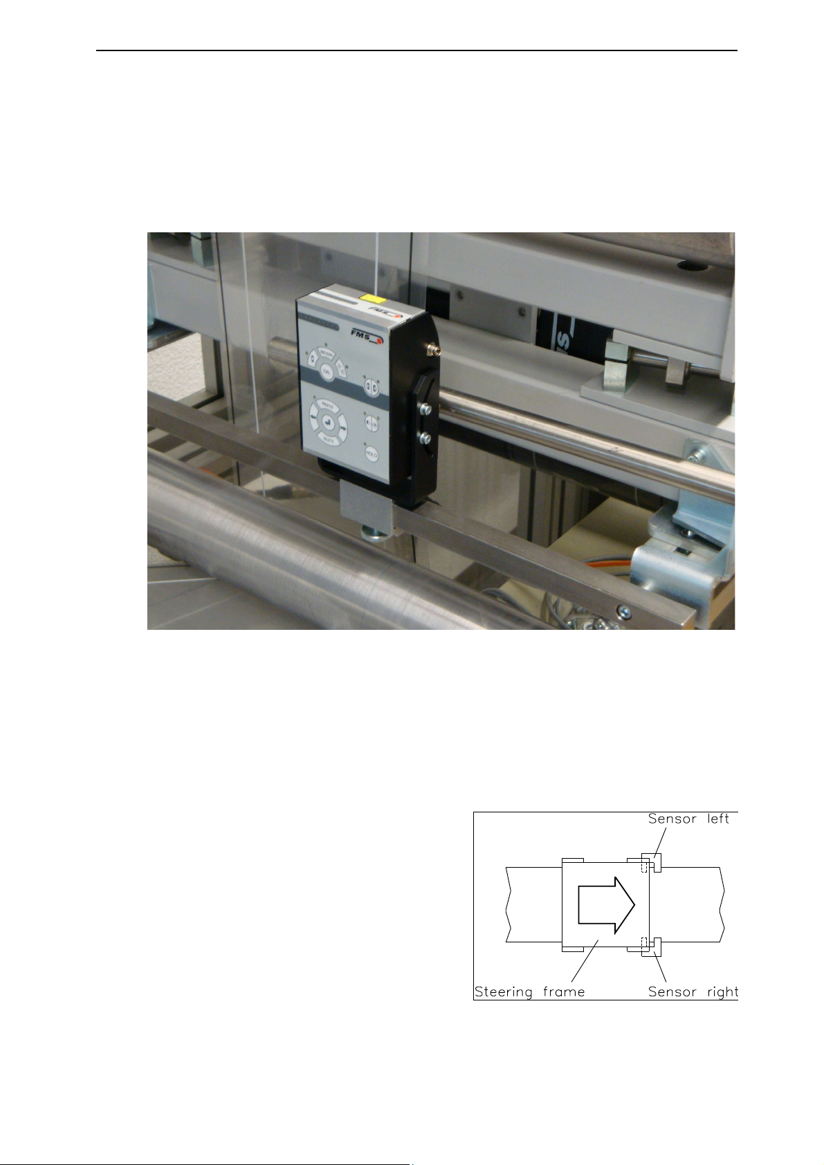
Fig. 5: Operational Parameters
DLS2012e

Operating Manual DLS2
9
6.2 Operation Panel
The operation panel (Fig. 6) consist of a foil type key pad and a LED-Display. The later
is used to display the actual line or edge position or status information of the sensor e.g.
in form of a LED pattern. A small green LED is assigned to all keys that own an
operation. These LEDs confirm the function that was activated
Fig. 6: Front panel DLS20006e

Operating Manual DLS2
10
6.3 Operating the DLS2 via the Front Panel
Key Key function during operation
Enter Calibration Procedure
Line detection mode (guides centre of line)
Pattern recognition (not operational)
Material edge mode
Line Reference Position (guides on the edge of line)
Enter profile management (list of predefined profiles)
Select previous / next profile from the list
Enter / implement / store profile
Delete profile from list
Measure contrast
Adjust focus
Sensor Detection Range Lights Spots
Change to hologram detection

Operating Manual DLS2
11
7Commissioning of the DLS2
7.1 Initialisation Phase
Note
If you retrofit a DLS2 sensor to an existing controller you have to restart the
controller after the installation of the sensor. This will allow the controller to detect
the DLS2 sensor correctly.
When powered up the DLS2 will initialise all parameters and will load the last profile
used. If no profiles or calibration data are available (e.g. when used the first time), the
sensor can’t go to Detection Mode and it needs to be calibrated. In this case the LED
display will indicate un-calibrated status with a light pattern with even and odd LEDs
flashing in alternation.
All even LEDs shining All odd LEDs shining
In order to enter the Detection Mode the DLS2 needs to be calibrated. The following
section 7.2 describes how to initialise and calibrate the DLS2 sensor. If an existing
profile with calibration data was loaded the sensor will change to the Detection Mode.
The LED line will in this case display the position of the line or edge depending of the
used mode.
7.2 Quick Installation Guide / Initialisation Procedure
The following procedure deals with commissioning the DLS2 sensor in line detection
mode. The initialisation in other modes (e.g. edge detection) is carried out analogous.
Instructions and information for the other modes can be found in section 8 „Different
Operation Modes“.
Initialisation Procedure:
1. Mount the sensor on the steering frame (see section 5.1 and 5.2)
2. Wiring the sensor (see section 5.3)
3. Choice of material: Choose a white paper web with a printed black line of 2 mm
[0.08“]
4. Perform Horizontal Positioning of DLS2 (see section 7.3)
5. Perform Focus Adjustment Procedure (see section 7.4)
6. Do Contrast Measuring (see section 7.5)
7. Perform Calibration Procedure (see section 7.6)
8. If necessary store profile of calibration (see section 9.3)

Operating Manual DLS2
12
7.3 Horizontal Positioning
In Normal Operation Mode an adjustment add can be called up by pressing three times
the key. The two small green LEDs above the key will light indicating that the
adjustment mode was activated. The sensor will project two small red light dots which
are vertically staggered. The sensor can be positioned by moving it along the rail until
the dots cover the object (line or edge) it has to recognise on the material. Once aligned,
the sensor can be locked by a corrugated-head screw.
The horizontal adjustment mode can be terminated by either pressing the key once
or waiting 30 sec.
7.4 Adjustment of Focus
The quality of the line or edge detection depends form several parameters. The focus is
an important parameter for proper functioning of the sensor. The focus is given by the
correct distance between sensor and material web. The best way of adjusting the focus
distance is by using a suitable material with a printed straight line with good contrast.
There is a procedure to set the correct focus distance. The procedure is started by
pressing twice the key. The small green LED on the right side of the key will
light. The focus quality can be influenced by moving the sensor closer or farther away
from the material. The improvement of the focus is indicated by the LED pattern as
follows:
Focus Quality LED-Display
Badly adjusted focus
→improving ←
Well adjusted focus
Best achievable focus
The focus adjustment procedure can be terminated by either pressing the key once
or waiting 30 sec.

Operating Manual DLS2
13
7.5 Contrast Measuring
The contrast describes the transition of the printed line and its background (dark - bright
intersection). The higher the contrast the better will be the detection of the line. The
contrast can be measured by pressing once the key. The small green LED on the
left side of the key will light. The contrast quality is visualised by the LED pattern as
follows:
Contrast Quality LED-Display
Very bad contrast
None LED is shining
Bad contrast
→improving →
Good contrast
Excellent contrast
The Contrast Measuring can be terminated by either pressing the key once or
waiting 30 sec.

Operating Manual DLS2
14
7.6 Sensor Calibration
The Calibration Procedure can be considered as a learning and optimisation process of
the sensor. The DLS2 gathers the characteristics of the line. Properties like line width,
contrast on left line edges, contrast on the right line edge and line colour are measured
and stored. The line must fulfil certain quality criteria (contrast, dimensions etc.) to be
recognised as a line. If these criteria are not fulfilled the calibration will fail and an error
pattern will appear on the LED-Display.
The calibration is started with the selection of the operation mode (ref. to section 8).
Press the key that complies with your application:
Line Detection (centre of line) Pattern Recognition
Line Edge Detection Hologram Detection
Material Edge Detection
After the operation mode choice start the calibration by pressing the key for
longer than half a second. During the calibration all LED will flash.
Calibration Result LED-Display
If the calibration was successful, the sensor will
display the actual line or edge position in relation
to the sensor detection range.
line detection
edge detection
At unsuccessful calibration the sensor will display
an error pattern. Even and odd LED will flash
alternating.
After a successful calibration and a test run the object data (calibration data) can be
stored as a profile (ref. to section 9 „Profile Management“)

Operating Manual DLS2
15
8Different Operation Modes
The DLS2 can detect different objects on a wide range of carrier materials. Following
objects can be defined:
•Straight lines ●Holographic lines
•Intermittent lines ●Holographic pattern
•Material edges ●Printed pattern
In order to optimise the detection of above objects the DLS2 sensor must be set in the
right operation mode. There are 5 operation modes:
•Line Detection ●Hologram Detection
•Line Edge Detection ●Pattern Recognition
•Material Edge Detection
8.1 Line Detection
In Line Detection Mode the sensor can detect lines from 0.5 mm to maximal 5.0 mm.
The characteristics of a line are gathered in the Calibration Procedure. Properties like
line width and the contrast on both line edges determine and describe each particular
line. A line will only be recognised as line, if following limits are adhered:
1. The line width may not differ more then ±35% from the reference line.
2. The absolute contrast may not differ more then 40% from the reference line
3. The contrast steepness may not differ more then 40% from the reference line
4. The direction of contrast change must match on both sides with the reference line.
To bring the sensor in Line Detection Mode press the key. The small green LED
above the key will light to confirm that this mode is active. The sensor will always follow in this
mode the centre of the line.
8.2 Line Reference Position
The line Detection mode distinguishes between three different reference positions:
•Line edge left
•Line edge right
•Line centre
The Reference Position can be chosen with the key. The small green LEDs above the
key indicate which Reference Positions is active.

Operating Manual DLS2
16
8.3 Material Edge or Line Detection Mode
This operation mode enables to recognise an edge of a material web or the edge of a
wide line. The edge must fulfil certain parameters to be recognised as an edge:
1. The absolute contrast may not be smaller then 50% from the reference edge
2. The contrast steepness may not be smaller then 50% from the reference edge
3. The direction of contrast change must match with the reference edge
The Edge Mode can be chosen with the key. The small green LED above the key will
light to confirm that this mode is active.
Operation Mode LED -Display
The line detection mode is indicated by one shining
LED that gives the position of the line in relation to
the sensor detection range. If none LED is shining,
the sensor can’t recognise the line.
←moving →
The edge detection mode is indicated by several
shining LEDs that gives the position of the material
edge in relation to the sensor detection range. If none
LED is shining, the sensor can’t recognise the edge.
←moving →
8.4 Hologram Detection
Materials with holograms require different illumination conditions as material with
printed lines. To accommodate for this requirements there is a dedicated operation
mode.
The sensor can be set to this special operation mode by pressing the key. The
small green LED above the key will light to confirm that the mode was activated. The
switch to Hologram Detection requires a re-calibration of the DLS2, if no profile for
such a material-object combination exists. The calibration in the Hologram Detection
Mode is carried out analogous to the procedure described in section 7.6 “Sensor
Calibration”.
8.5 Pattern Recognition
Not operational

Operating Manual DLS2
17
8.6 Normal Operation
In normal operation the display shows the position of the line or the edge as described in
section 8.3. If the line or edge is missing none LED will shine. Longer unintended line
interruptions are recognised by the DLS2 and it sends a special signal to the web guide
controller. In such a case the controller blocks the steering frame at the actual position
until the line is recognised again.
Note
In web guiding systems all equipped with FMS components and a DLS2 sensor it may
happen that the web guide controller blocks the steering frame. This protective
function is activated when the line is interrupted and impossible to be detected.
The DLS2 generates at unintentional line interruption an alarm signal that can be
used to shutdown the production line preventing the steering frame skittering away
and creating material loses.
8.7 Reset to Default Parameter Set
Factory settings of the DLS2 can be re-established by:
Holding the two keys + while powering–up the device.
The process will be confirmed by one LED light wandering from the middle to the ends
of the row and back.
←on →
→off ←

Operating Manual DLS2
18
9Profile Management
Once the material/line/edge combinations have been calibrated they can be stored as a
profile. The profiles contain the most important properties of the calibration (contrast,
line dimension, edge quality etc.). Profiles enable a quick and flexible use of the
production line since they can quickly be accessed. Machine set-up for periodically used
materials is simplified (no need for recalibration) resulting in considerable time savings.
9.1 Profile Management Panel
The rose-like control panel (see Fig. 7) is
used for profile management. With it profiles
can be stored, deleted or implemented. After
entering the operation mode „Profile
Management“ (by pressing the key
for longer than 0.5 sec.) the LED-Display
will show the status of the profiles (see Fig.
8).
Each of the 9 elements on the LED-Display
represents a profile. Hence the DLS2 can
store 9 different profiles. The status of the
profiles are visualised by the manner the
LED-Element is shining. Following table
shows the different profile states.
LED-Element Profile Status
Not shinin
g
Unselected profiles
Flashing Empty profile storing place
Permanently shining Selected calibration data (profile)
Fig. 7: Profile Management Panel
DLS2010
Fig. 8: Profile Storing Places
DLS2011e

Operating Manual DLS2
19
9.2 Call Profile and Implement
If a profile is fetched from the memory and adopted, the actual calibration data of the
DLS2 is overwritten.
1. Enter operation mode „Profile Management“ by pressing the key for longer
than 0.5 sec.
2. Select an existing profile with the keys. An existing profile is marked by
shining LED.
3. Press the key for longer than 3 sec. to adopt the selected profile. This action
terminates the Profile Management mode and brings the DLS2 to normal operation.
9.3 Save Profile
1. Calibrate DLS2 with material-reference-combination.
2. Check calibration with a test run.
3. Enter operation mode „Profile Management“ by pressing the key for longer
than 0.5 sec.
4. Select a free profile storing place with the keys. A free profile storing place is
marked by a flashing LED. It’s not possible to overwrite an existing profile without
deleting the profile beforehand. .
5. Press the key for longer than 0.5 sec. to save the profile in the free storing
place. The LED will change from flashing to permanent shining. If the saving
process was successful, the DLS2 will go to normal operation mode.
9.4 Delete Profile
1. Enter operation mode „Profile Management“ by pressing the key for longer
than 0.5 sec.
2. Select an existing profile with the keys. An existing profile is marked by
shining LED.
3. Press the key for longer than 3 sec. to delete the selected profile. The LED
will change from permanent shining to flashing. The sensor will then go to normal
operation mode.

Operating Manual DLS2
20
10 Technical Data
Parameter Value
Sensin
g
width 8mm
Max. line width 5mm
Min. line width 0.5mm
Resolutio
n
0.06mm
Measurin
g
rate 2 ms
Output si
g
nal 0...10V 0…10V
Power suppl
y
24VDC (18…30VDC)
Temperature ran
g
e -10 …+50°C
Protection class IP 54
11 Trouble Shooting
Error Possible cause and solution
Wrong measuring results,
malfunction of the sensor
Electrostatic discharge of the web to the material
sensor can lead to malfunctions.
An additional electrostatic protection band can be
used as illustrated below.
FMS Force Measuring
Systems AG
Aspstrasse 6
8154 Oberglatt (Switzerland)
Tel. 0041 1 852 80 80
Fax 0041 1 850 60 06
info@fms-technology.com
www.fms-technology.com
FMS USA, Inc.
2155 Stonington Avenue
Suite 119
Hoffman Estates,, IL 60169
(USA)
Tel. +1 847 519 4400
Fax +1 847 519 4401
fmsusa@fms-
technology.com
FMS (UK)
Aspstrasse 6
8154 Oberglatt (Switzerland)
Tel. +44 (0)1767 221 303
FMS (Italy
)
Aspstrasse 6
8154 Oberglatt (Switzerland)
Tel. +39 02 39487035
Table of contents
Other FMS Accessories manuals