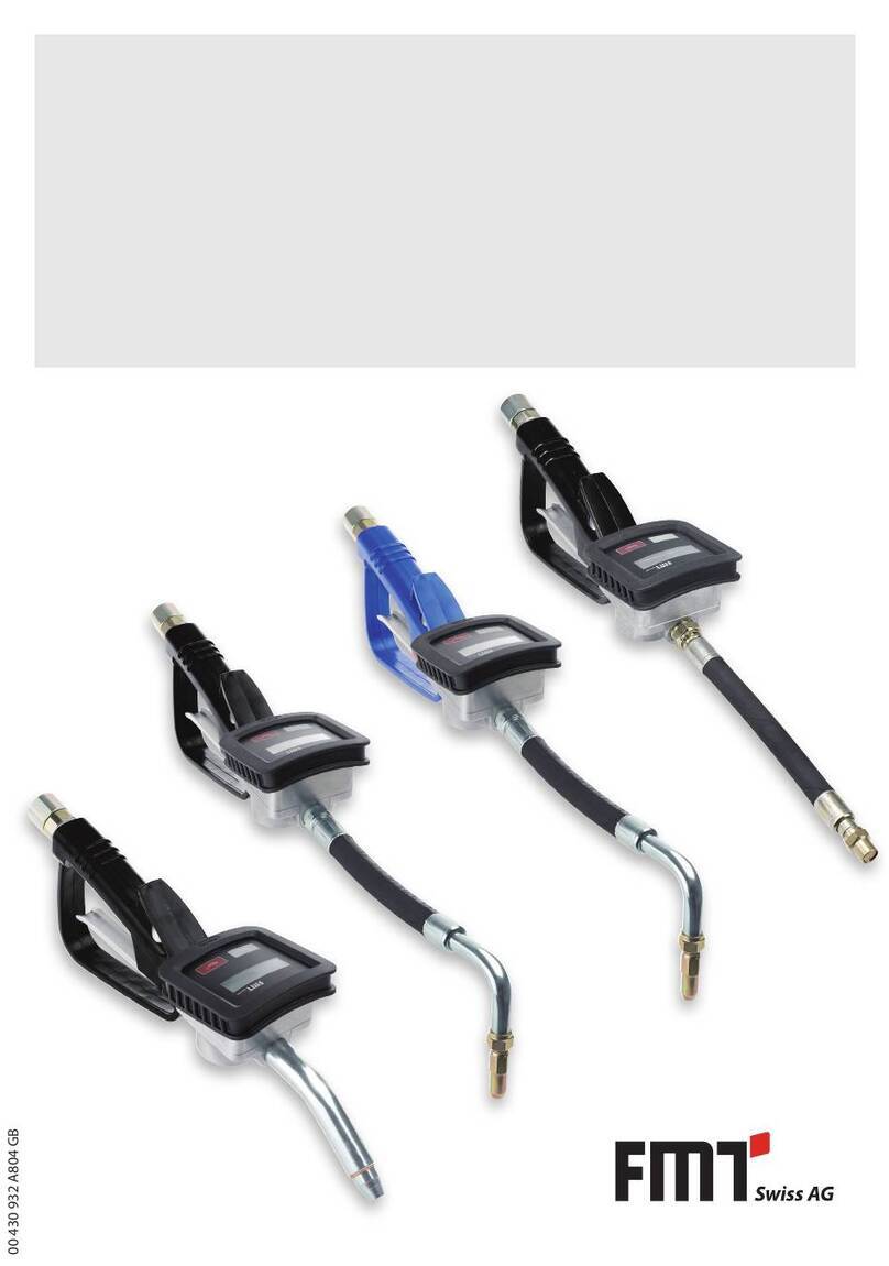
FMT Swiss AG Digital In-Line Meter User manual

88 376 932 A802 GB Version 16.09.2020
In-Line Meter digital
for various media
Operating Instructions
Contents:
1. General information
1.1 Intended use
1.2 Construction and description of function
1.3 Technical data
2. General safety information
2.1 Information concerning work safety
2.2 Explanation of the safety information
used
2.3 Risks when using the in-line meter
3. Assembly
3.1 to 3.4
4. Operation
4.1 Switching on the Meter
4.2 Resetting the Trip Counter to record
a new measurement
4.3 Displaying a Part Sum (subtotal)
4.4 Resetting Part Sums and Total
4.5 Advice about Measurement Accuracy
4.6 Calibration
4.7 Switching off the Meter
5. Maintenance
6. Repair/Service
7. Replacement parts list
8. Declaration of the manufacturer

In-line meter, digital Operating Instructions
2
1. General information
1.1 Intended use
The digital in-line meter is only suitable for operation with low viscosity, hardly ˜ ammable liquids.
The function of the electronics is guaranteed in a temperature range from -10 °C to +40 °C.
The in-line meter is pre-calibrated for use with fuel oil and diesel or AdBlue.
The intended use also includes an operation following the Operating Instructions.
Any use beyond these parameters or any changes can lead to serious risks and is regarded as use
that is contrary to the intended purpose. The operator is liable for any damage caused by improper
use.
1.2 Construction and description of function
The in-line meter is designed to be used for unproblematic liquid measurement.
The measurement recording of this in-line meter will be e° ected ˜ uidically based on the principles
of a turbine wheel ˜ ow meter. The measured values are transmitted packing- and contactless,
electronically processed and displayed.
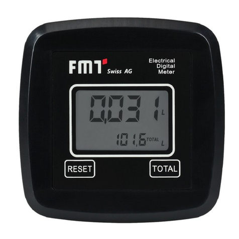
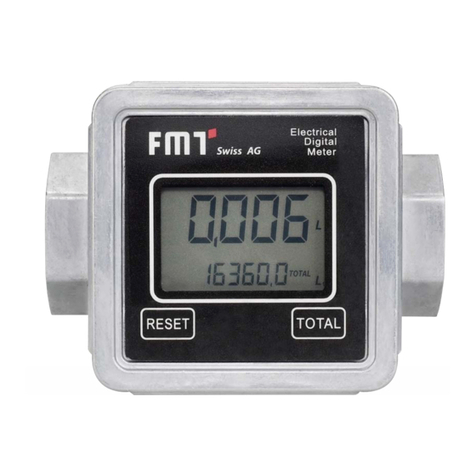
The in-line meter o° ers an easy to read double-line display switching on automatically when
starting an operation or when pushing any button on the display keyboard. The ÿrst display line
shows the currently dispensed quantity of liquid. At the same time, the second display line counts
the total or a user-related or vehicle-related subtotal (1 to 9 subtotals available).
An automatic data storage is provided even when the battery will have to be changed.
The clear foil keyboard is easy to operate and is designed to be used for inputs of user parameters.
The complete display of the in-line meter is 4 x 90° rotatable so reading of the displayed
information is guaranteed in any position of installation.

In-line meter, digital Operating Instructions
3
1.3 Technical data
Designation In-Line meter, digital
Measurement principle
Radial flow turbine wheel
Material (medium contact) POM/stainless steel/Viton®
Flow rate 10 to 55 l/min
Operating pressure (max.) 2 bar
Bursting pressure 4 bar
Measuring tolerance
± 1 %
Repeating accuracy ± 0.8 %
Display 1. line six digits, 15 mm high
Display 2. line
six digits, 7 mm high
Resolution approx. 0.03 litres
Connection thread G ¾ “ or G 1“ female, G 1“ male
Weight
305 g
Temperature range,
evaluation electronics from –10 °C to +40 °C
2. General safety information
2.1 Information concerning work safety
The digital in-line meter is designed and manufactured according to the appropriate safety and
health requirements of the relevant EC guidelines.
Nevertheless, any use contrary to the intended purpose can lead to serious risks.
For the operation of the in-line meter pay attention in any case to the local safety and accident
prevention regulations and pay attention as well to the recommendations of these
Operating Instructions.
2.2 Explanation of the safety information used
The safety information used in these Operating Instructions refer to following risk level. This risk
level is marked in any case in these Operating Instructions with following signal word and
pictogram.
Pictogram Signal word Consequences of not observing of the safety advises
Warning
Information Background knowledge or tips the correct handling of
the product
Death or most severe physical injurie

In-line meter, digital Operating Instructions
4
2.3 Risks when using the in-line meter
Warning!
The digital in-line meter is designed for use with low viscosity, hardly flammable, self-
lubricating media only.
The in-line meter may be used in explosion safe areas only.
Information
Leaking fuels can cause environmental damage.
Pay attention in any case to your local environmental safety regulations.
3. Assembly
Before assembly, remove all packaging material.
3.1 Pump with threads G 1“ male (Fig. 1)
Screw sleeve adapter G 1“ female/female (1) half a turn onto the male connecting thread of the
pump.
Press flat packing (3) into the sleeve adapter (1).
Connect the pump with the in-line meter (2) screwing the sleeve adapter (1)
simulteaneously.
3.2 Pump with threads G ¾“ male (Fig. 2)
Screw sleeve adapter G 1“ female/G ¾“ female (1) half a turn onto the male connecting thread
of the pump.
Press flat packing (3) into the sleeve adapter (1).
Connect the pump (G ¾“ male) with the in-line meter (2) screwing the sleeve adapter (1)
simulteaneously.
Accessories for 3.2 (Fig. 2)
Art. no.
Adapter G 1"/G ¾"
88 375
Hose fitting G 1"
87 936
2-ear terminal clip
88 030

In-line meter, digital Operating Instructions
5
3.3 Press flat packing (3) into delivery hose fitting (4) and connect the male connecting
thread (5) of the meter to the delivery hose.
3.4 After assembly, check the system for tight connections and possible leaks.
Fig. 1 Fig. 2
4. Operation
4.1 Switching on the Meter
The meter is switched on by pressing the Start button. It displays the last measured value. When
starting a dispensing operation (recognised flow rate) the measurement will continue
automatically from the last measured value.
4.2 Resetting the Trip Counter to record a new measurement
The last measured value (large display) can be deleted by pressing the Reset button.
4.3 Displaying a Part Sum (subtotal)
Pressing the ▲▼buttons enables switching between TOTAL and part sums 1 to 9.
4.4 Resetting Part Sums and Total
Resetting Part Sums 1 to 9
By simultaneously pressing the Start and ▲ buttons for approx. 5 seconds, the displayed part
sum will be reset to 0,0.
Resetting the TOTAL sum
Unscrew the 4 screws at the back of the meter.
Carefully remove the meter cover with display from the housing.
Unscrew the 2 screws from the battery carrier.
Remove the batteries from the carrier.
Press the Reset button and at the same time insert the batteries back in the carrier.
The TOTAL sum will then be reset back to 000000.
Reassemble the meter in the reverse order.

In-line meter, digital Operating Instructions
6
4.5 Advice about Measurement Accuracy
The built in meter recognises, according to the operating conditions, the amount of fluid flowing
through it, and is factory precalibrated for use with heating oil and diesel fuel. The maximum
accuracy will be achieved when dispensing at a constant delivery rate.
However, various influences can affect the achievable measurement accuracy:
Viscosity and type of delivered fluid.
Strong pulsation and power variation of the delivery pump.
Installation conditions.
4.6 Calibration
By pressing both the ▲▼buttons for approx. 5 seconds the meter changes to calibration mode.
There are two possibilities:
Reading Current Calibration Value
To display the current calibration value, the Trip counter must first be reset to zero before changing
to the calibration mode. Do this by pressing the Reset button. When the calibration value is
displayed, the meter can be returned to normal operation, without changing the value, (last
calibrated value is retained) by pressing the Start button. Pressing the Reset button sets the
calibration factor back to the default value (factory calibration) and switches the meter back to the
operating mode.
Changing the Calibration value
By pressing both ▲▼buttons for approx. 5 seconds, with a trip counter value other than zero,
the meter changes to calibration mode.
By pressing the arrow button ▲ the value is adjusted upwards, by pressing the button, the value
is adjusted downwards.
By pressing both the ▲▼buttons for a further 5 seconds the displayed value will be stored and
calibration finished. The meter switches back to operating mode.
Example: Dispense fluid into an accurate measuring container (20 litre volume).
Switch the meter to calibration mode by pressing the ▲▼buttons.
By pressing either the ▲ or ▼buttons, change the displayed value to match the amount in the
container.
Store the adjusted value by pressing the ▲▼buttons.
4.7 Switching off the Meter
The meter can be switched off by pressing the Start button for a long period (approx. 5 seconds). If
the meter is not active for more than 90 seconds, it switches off automatically.

In-line meter, digital Operating Instructions
7
5. Maintenance
As a matter of principle, the in-line meter is a low-maintenance product.
Based on the operator's obligations following parts should be checked regularly, in order to avoid
environmental damages or damages to property or persons.
The meter housing and the connections must be checked for damages and leaks regularly.
In case of a change of the battery, carefully open the meter housing and remove the battery as
shown above. Insert a new 3.6 V lithium battery (type SL 360S) and lock the housing.
6. Repair/Service
The in-line meter has been constructed and manufactured meeting highest quality standards.
If a problem occurs despite all quality precautions, please contact our sales department:
FMT Swiss AG
Tel +49 9462 17-246
Fax +49 9462 1063

In-line meter, digital Operating Instructions
8
7. Replacement parts list
Fig. 3
Parts list to Fig. 3
Pos.
Designation
Art. no.
1
Display, complete red / blue 88 368 / 88 368 005
2
Housing
88 369
3
Throttle, D 12
88 370
4
Adapter, G 1“ I x G 1” r
88 371
5
Sealing ring, 30 x 19.5 x 2
88 372
6
Lithium battery; 3.6 Volt
88 373
8. Declaration of the manufacturer
We herewith declare that the product described below corresponds with the EC guidelines with
regards to design and type of construction and as well to the version market by us. This declaration
will loose its validity in case of any changes of the product being made without our agreement.
Product type
In-line meter, digital
EC guideline
EC guideline Electromagnetic Compatibility
(89/336/EEC) in the version of 93/31/EEC
National standards applied
DIN VDE 0843 T1
31.12.2007 FMT Swiss AG
___________________________
Dipl.-Ing. Rudolf Schlenker
FMT Swiss AG
Fluid Management Technologies Swiss AG • Gewerbestr. 6 • CH-6330 Cham/Schweiz
Tel. +41 41 712 05 37 • Fax +41 41 720 26 21 • info@fmtag.ch • www.fmtag.ch
Table of contents
Other FMT Swiss AG Measuring Instrument manuals
Popular Measuring Instrument manuals by other brands

Endress+Hauser
Endress+Hauser prowirl 70 technical information
MONARCH INSTRUMENT
MONARCH INSTRUMENT Nova-Strobe dax instruction manual

Vega
Vega VEGAPULS WL 61 operating instructions

Nitronic
Nitronic HRC3070 operating instructions
DH Instruments
DH Instruments DUAL MID FLOW instruction sheet

Leica
Leica TS12P user manual
