FMT Swiss AG 23295 User manual
83 432 A801 GB
Turbine ow meter

2
GOperating instructions for turbine ow meter
Contents
General details1. ______________________________________________________________________3
Intended use1.1. ________________________________________________________________________3
Design and functional description1.2. ______________________________________________________3
Display LCD1.2.1. _________________________________________________________________________4
User controls1.2.2. ________________________________________________________________________4
Measuring chamber1.2.3. __________________________________________________________________5
Battery compartment1.2.4. _________________________________________________________________5
Technical data1.3. _______________________________________________________________________5
General safety instructions2. ____________________________________________________________6
Information on safety at work2.1. __________________________________________________________6
Signs and symbols used in the safety instructions2.2. __________________________________________6
Hazards when handling the turbine ow meter2.3. ____________________________________________6
Assembly3. ___________________________________________________________________________6
Installation4. _________________________________________________________________________7
Routine operation5. ___________________________________________________________________7
Output of liquid during standard operation (Normal Mode)5.1. __________________________________8
Resetting partial volumes5.1.1. _____________________________________________________________8
Resetting the resettable total volume (RESET TOTAL)5.1.2. ________________________________________9
Output of liquid with display of current ow rate (Flow Rate Mode)5.2. ____________________________9
Resetting partial volumes5.2.1. ____________________________________________________________10
Calibration6. ________________________________________________________________________10
Denition6.1. _________________________________________________________________________10
Why calibrate the meter at all?6.2. ________________________________________________________10
Calibration mode6.3. ___________________________________________________________________11
Displaying the valid calibration factor - resetting the factory calibration factor (if necessary)6.3.1. ______11
Calibration during simulated operation6.3.2. _________________________________________________13
Meter calibration during simulated operation6.3.3. ____________________________________________13
Changing the K FACTOR directly6.3.4. _______________________________________________________15
Conguration of the turbine ow meter7. _________________________________________________17
Service8. ____________________________________________________________________________18
Exchanging batteries8.1. ________________________________________________________________18
Cleaning8.2. __________________________________________________________________________19
Troubleshooting9. ____________________________________________________________________19
Repairs/service10. _____________________________________________________________________20
Manufacturer‘s declaration11. ___________________________________________________________20
Exploded drawingh12. _________________________________________________________________21
3
Operating instructions for turbine ow meter G
1. General details
1.1 Intended use
This turbine ow meter has been designed and built for measuring volumes of various media featuring
dierent viscosities, and for the storage of data so collected.
The turbine ow meter is intended for installation at the end of an output hose, e.g. a hose reeler.
1.2 Design and functional description
The turbine ow meter is a uid meter with electronic counter & memory and digital display.
The medium owing through the meter sets a turbine in rotation. The revolutions of the gears are
converted into electronic pulses and sent to the electronic counter by a Reed switch. The electronics,
nally, uses a certain multiplication factor to convert the pulses into an intelligible volume of liquid
having gone through the device, which is then shown on the LCD display.
The multiplication factor has been pre-set at the factory using an average that has turned out to be
useful in normal operation. However, it can be easily adapted to specic requirements by the user. The
total volume measured is stored and can be called up by pressing the TOTAL button.
Data collection and analysis are being constantly monitored by the electronics. Errors are reported
immediately.
The electronic counter needs a two-phase input signal that‘s being monitored for phase errors. A self
test is being carried out before every RESET. The user needs only two membrane key switches for ope-
ration: RESET and TOTAL (i.e. total volume). The body of the device is made of aluminium.
The electronic components and LCD display sit at the top of the turbine ow meter, far away from and
well insulated against the wet measuring chamber. There is a cover to protect them against the wor-
king environment.
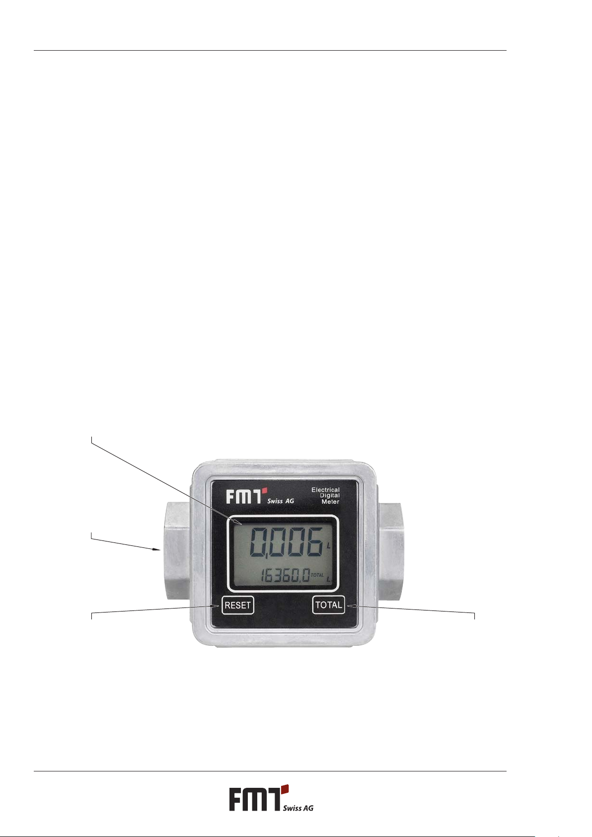
MEASURING CHAMBER
RESET BUTTON
DISPLAY LCD
TOTAL BUTTON

4
GOperating instructions for turbine ow meter
1.2.1 Display LCD
The meter‘s LCD display is equipped with two numeric registers and dierent types of display modes
showing information to the user only when it is actually needed with the operation / function going on
at the moment.
Key:
Register of partial volume (5 digits with oating decimal: 0.000+99999) showing the amount of liquid1.
that has been delivered since the RESET button was last pressed
Battery charge2.
Display of the calibration mode3.
Register of total volume (6 digits with oating decimal 0.0-999999x10/x100) showing two dierent4.
kinds of total volumes:
4.1 Non-resettable total volume (TOTAL)
4.2 Resettable total volume (RESET TOTAL)
Total volume multiplication factor (x10/x100)5.
Type of total volume display (TOTAL / RESET TOTAL)6.
Units for total volume: L = litres, GAL = gallons7.
Flow rate8.
Display of measuring unit for partial volumes:9.
QTS = quarters; PTS = pints; L = litres; GAL = gallons;
The display can be adapted to the direction of ow in 90° steps. To do so, loosen the four screws (item
1). Now you can mount the display unit turned 90°.
Caution!
O-ring (item 10) must be re-mounted correctly.
Do not pinch or excessively twist the cables from the battery compartment (item 11) to the
PCB (item 14).
Then re-insert and tighten the screws (item 1).
1.2.2 User controls
There are two push buttons on the meter (RESET and TOTAL), each controlling two main functions
(pressed individually) and various auxiliary sub-functions (pressed simultaneously).
Main functions:
RESET button: Resetting the partial volume register and the (resettable) total volume register RESET
TOTAL.
TOTAL button: Calling up the calibration mode. Pressed together, the two buttons call up the
conguration mode where you select the unit of measurement.

5
Operating instructions for turbine ow meter G
1.2.3 Measuring chamber
The measuring chamber is located in the centre of the meter.
There is a turbine in the measuring chamber, set in rotation by the ow of liquid. Each revolution will
generate an electrical pulse that is processed by the microprocessor on the control circuit board.
The microprocessor uses a calibration factor (i.e. a‚weighting‘ assigned to each pulse) to convert the
pulses generated by the gears‘ revolutions into an intelligible value representing the volume of liquid
that has passed through. It is then displayed in the unit pre-set before in the corresponding registers of
the LCD display for partial and total volumes, respectively.
All of our turbine ow meters leave the factory with a default calibration factor = 1000 called
„FACTORY K FACTOR“. There is a possibility to calibrate the meter in order to adapt that factor to the
physical properties of dierent liquids.
However, there is always a possibility to return to the manufacturer‘s default setting.
1.2.4 Battery compartment
The meter is powered by two 1.5 V standard batteries (N1).
The battery compartment is inside the body. To replace the batteries, you must remove the cover.
1.3 Technical data
Designation 23295
Measuring system Turbine
Accuracy l/pulse 0,017
Flow rate range l/min 10 - 100
Operating pressure bar 40
Burst pressure bar 80
Storage temperature °C -20 to +70
Storage humidity R.H. 95 %
Max. operating temperature °C 60
Flow rate loss at max.
ow (with diesel oil) bar 0,2
Compatible liquids Heating oil, diesel, hydraulic oils
Viscosity range cSt 2 - 2000
Accuracy
(within ow rate range) ±0,5 %
Repeatability 0,2 %
Weight kg 0,39
Threads at
inlet and outlet 1“
Power supply (batteries) V 2 x 1,5
Lifetime of batteries (est.) h 14.000 - 30.000
Table 1-1: Technical data
6
GOperating instructions for turbine ow meter
2. General safety instructions
2.1 Information on safety at work
The turbine ow meter has been designed and built in compliance with the applicable safety and
health requirements of the relevant EU directives.
However, hazards may result from this product if it is not used for its intended purpose or with the
necessary care.
For all uses of this turbine ow meter, local safety and accident prevention regulations apply, as
well as the safety instructions in these operating instructions.
2.2 Signs and symbols used in the safety instructions
Safety instructions are indicated in this manual with the following keywords and pictograms:
Pictogram Keyword Consequences of failure to comply with the safety
instructions
Caution Possible risk of slight to medium physical injury or material
damage
In addition, a further instruction is used which gives general tips for handling the product.
Pictogram Keyword Meaning
Tip Background information and tips on the right way of using the
product
2.3 Safety instructions concerning hazards that may arise in connection with
the turbine ow meter
Caution!
The turbine ow meter has been designed and is suitable for operation with media of low
ammability, exclusively.
Do not operate this turbine ow meter in areas with potentially explosive atmospheres.
Tip
Be sure to know and respect, in particular, any water management laws that may exist. In
Germany, for instance, § 19g of the German Water Management Act („WHG“) provides that
equipment for lling must be designed, constructed, installed, maintained and operated in such
a way that bodies of water are not aected in any critical ways.
The owner / operator of lling equipment is obliged to permanently check and manage any such
equipment for compliance with the afore-mentioned requirements at the place of installation.
3. Assembly
The turbine ow meter comes fully assembled and ready to go.
There may be accessories that can or must be tted. This depends on the model you chose.
Tip
During assembly, make sure everything is perfectly clean. Take particular care that components
are well aligned and connected and t tightly.
7
Operating instructions for turbine ow meter G
4. Installation
The inlet and outlet of the turbine ow meter are aligned in a straight axis and equipped with 1“ threads.
The meter may be installed in any given position, as a xed unit in a pipeline and/or as a mobile unit on a
spigot.
The turbine ow meter does not have a pre-dened ow direction. Both ends may alternatively serve as
inlet or outlet, as needed. However, it is absolutely important that the side that is used as inlet (where the
pipeline arrives) is equipped with a lter with suitable performance characteristics. Solid particles getting
into the measuring chamber might clog up the turbine.
5. Routine operation
The turbine ow meter comes pre-assembled and ready to go.
Even after periods of prolonged storage, it will be ready for operation without any lengthy preparations.
The only action that may be necessary from time to time during normal operation is to reset the registers
of partial and/or resettable total volumes.
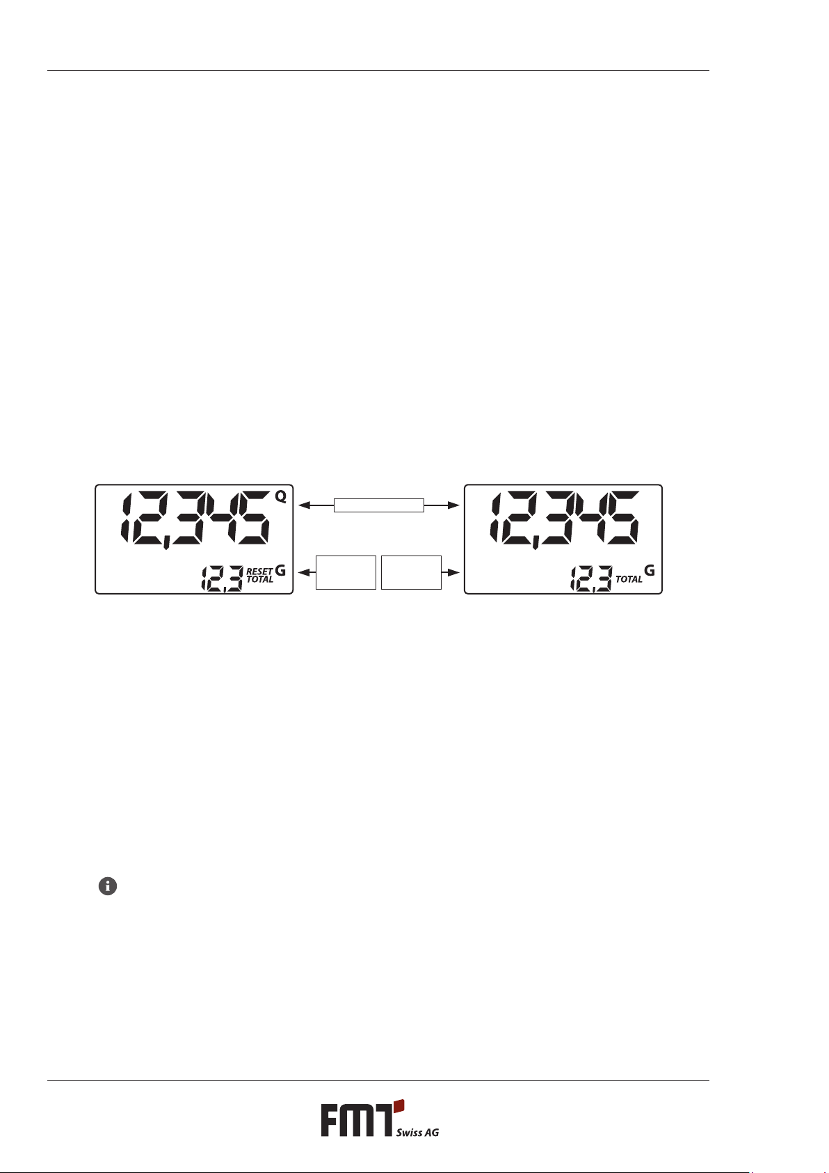
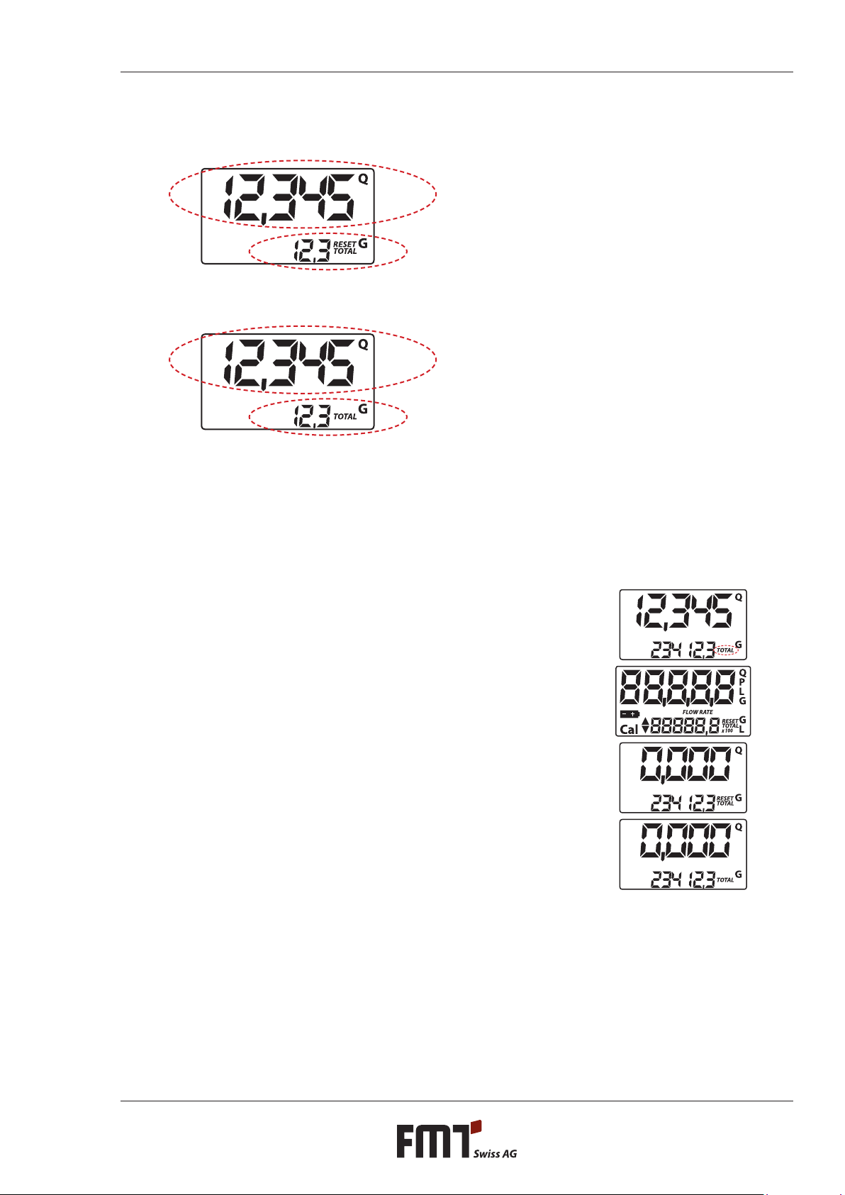
To accomplish that, call up the two displays for normal operation. The rst normal operation display
contains the partial volume and resettable total volume (RESET TOTAL). The other display shows the
partial volume and the non-resettable (absolute) TOTAL volume. The LCD automatically switches between
resettable and absolute total. This has been set at the factory and cannot be inuenced by the user.
Register of
RESETTABLE
TOTAL VOLUME
Register of
ABSOLUTE
TOTAL VOLUME
Register of partial volume
The register of the absolute total (TOTAL) cannot be reset by the user. It will continue counting during the
entire lifetime of the meter. The resettable and non-resettable registers of total volumes (RESET TOTAL and
TOTAL) share the same‚window‘ and the same digits of the LCD display. For that reason, the two numbers
cannot be viewed at the same time.
The turbine ow meter has been programmed so that the one or the other total is visible at certain
moments / in certain modes during operation (never both at a time):
The absolute total volume (TOTAL) is visible in standby mode.
The resettable total (RESET TOTAL) is visible at the following times / in the following modes:
- For a short moment (several seconds) after resetting the (resettable) partial volume.
- During the output of liquid.
A few seconds after output of the liquid this short time span expires and the meter switches to standby
mode. The display of the bottom register shows the absolute total volume.
Tip
For the display of total volumes, there are 6 digits available, plus two icons x10/x100. The
increments are activated in the following sequence:
0,0 ---> 99999,9 ---> 999999 ---> 100000 x10 ---> 999999 x10 ---> 100000 x100 ---> 999999 x100
8
GOperating instructions for turbine ow meter
5.1 Output of liquid during standard operation (Normal Mode)
During standard output of liquid, the meter will count and at the same time display the
volume having gone through the device so far, and the resettable total (RESET TOTAL).
Accidental pressing of the RESET or TOTAL button does not have any eect in this state.
A few seconds after you‘re nished, the display of the lower register will change from resettable total to
absolute total: The word RESET above the word TOTAL will disappear, and the value of the resettable
total will be replaced by the absolute total.
We call this state (or mode)„standby“. It will persist as long as the user does not carry out any more actions
on the meter.
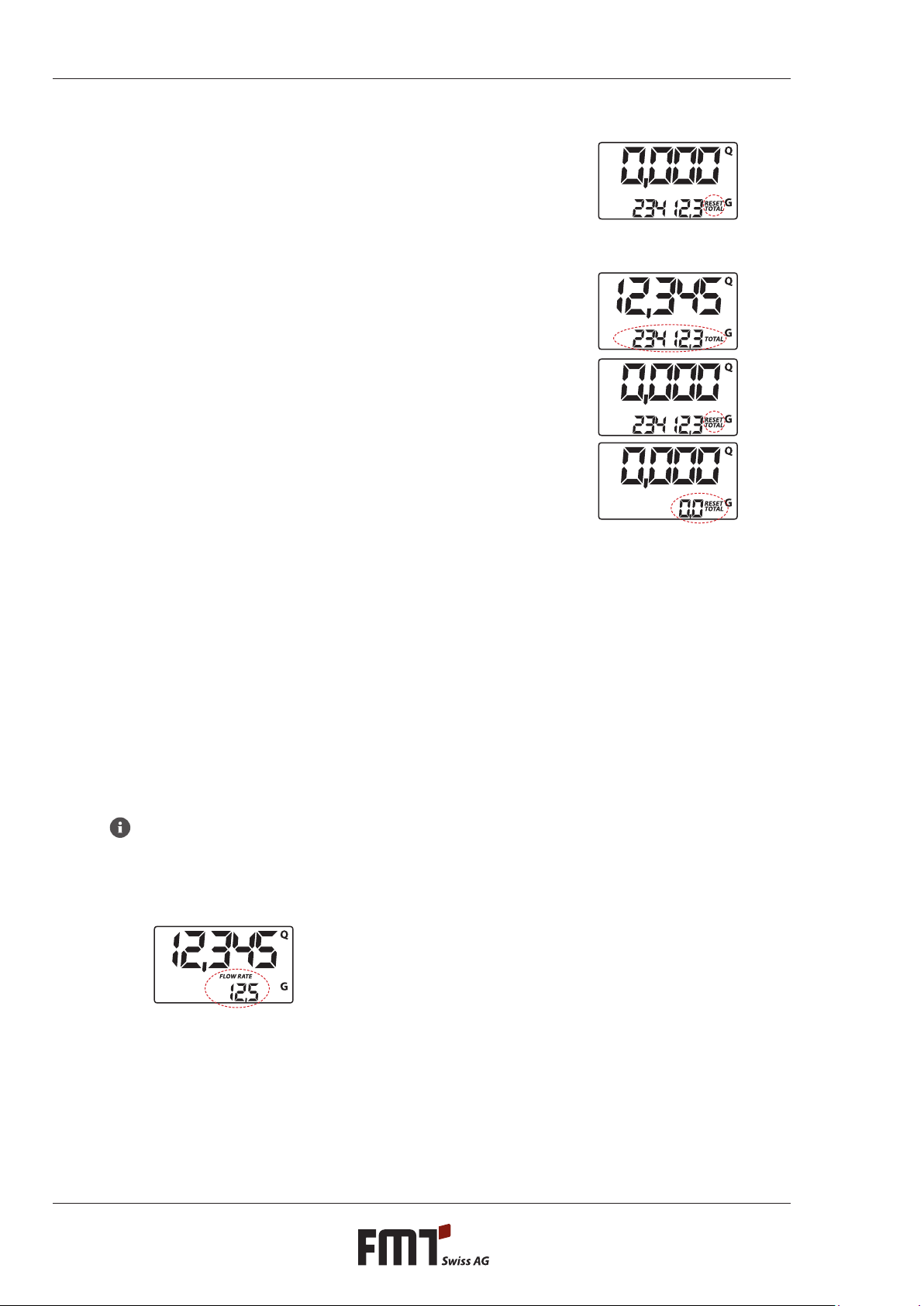
5.1.1 Resetting partial volumes
For resetting the partial volume register: Press the RESET button
while the meter is in standby, i.e. when you see the word TOTAL in
the display.
When you press RESET, the display will rst switch on all the
segments, one after the other, and then switch them all o again.
When the reset is complete, the display will rst show the partial
volume having been reset and then RESET TOTAL.
After a couple of seconds, RESET TOTAL will be replaced by the
NON-resettable total amount (TOTAL).
9
Operating instructions for turbine ow meter G
5.1.2 Resetting the resettable total volume (RESET TOTAL)
You can reset the resettable total only if you have reset the
register of the partial volumes before. To reset the resettable total:
press RESET for several seconds. The display will show the words
RESET TOTAL (see g.):
You must carry out the following steps (in this order):
1. Wait until the display is back to default standby mode (i.e.
showing only TOTAL).
2. Press RESET shortly.
3. The meter will now start resetting the partial volume register.
4. While the display shows all segments, press and release the
reset button.
5. The display will show all the segments again. Only then follows
the phase where all segments are switched o.
Finally, there will be a display showing the total that has been
reset (RESET TOTAL).
5.2 Output of liquid with display of current ow rate (Flow Rate Mode)
It is possible to output a liquid and have the following displays available:
Partial volumes having been output
Current ow rate (Flow Rate) in [unit of partial volume per min.], as shown below.
This is how you get into this mode:
Wait until the meter is in default standby mode (i.e. the display shows only the total volume).
Press TOTAL shortly.
Start output operation.
The display of the current ow rate will be updated every 0.7 secs. For that reason the display may‚utter‘
somewhat with low ow rates. However, the higher the ow rate, the more stable the display will be.
Tip
The current ow rate will be shown in the unit set for the partial volume register. That means if
partial and total volume have been set to dierent units (as shown in the example below) you
must bear in mind that the ow rate shown is in the unit set for partial volumes. In the example
shown, the ow rate is in QTS./min.
The word GAL next to the ow rate refers to the register of the (resettable and NON-resettable) total
volumes which will be displayed again as soon as you leave the‚current ow rate‘ display mode.
In order to go back to the default standby mode, press the TOTAL button again.
Accidental pressing of the RESET or TOTAL button does not have any eect in this state.

10
GOperating instructions for turbine ow meter
Tip
RESET TOTAL and absolute total (TOTAL) are not shown in this mode. However, the values
nevertheless go up, of course. You can check after you‘re nished. Wait for the default standby
mode and press TOTAL shortly.
5.2.1 Resetting partial volumes
In order to reset the partial volume register, you must rst complete the output of liquid. Wait until the
display shows a ow rate of 0.0 (see g.) and then press RESET shortly
.
The eect is dierent from what you would have if you press Reset in default standby mode. There is no
phase where all the segments are rst switched on and then o again. Instead, the register will display the
reset partial volume immediately.
6. Calibration
6.1 Denition
Calibration factor ->„K FACTOR“:
This is the multiplication factor the system ascribes to the electronic pulses it receives in order to convert
them into a plain unit of measurement.
FACTORY K FACTOR: Calibration (default) factor pre-set at the factory.
Factory K Factor = 1000.
This calibration factor guarantees the highest degree of precision under the following operating
conditions:
Liquid Engine oil type 10W30
Temperature 20 °C
Flow rate 2-20 l/min
You can always return to the original Factory K Factor even after you have changed the value. The
procedure is simple.
USER K FACTOR: This is the calibration factor the user has set to adapt the meter to specic
requirements (i.e. the user has carried out a calibration procedure).
6.2 Why calibrate the meter at all?
The turbine ow meter comes to you with a calibration factor pre-set at the factory that will guarantee the
most precise measurements under most operating conditions.
If calibration is necessary, it should be conducted under the operating conditions in which the meter is
used, such as in the following extreme conditions:
liquids having a viscosity close to the admissible limits (e.g. antifreeze with low viscosity, high-viscosity
oils for gearboxes)
extreme ow rates (i.e. close to upper or lower limits)

11
Operating instructions for turbine ow meter G
6.3 Calibration mode
The turbine ow meter has a fast and precise electronic calibration mode where you simply change the so-
called calibration factor (K FACTOR).
There are two calibration procedures you may choose from:
Simulated operation + calibration (requiring actual output of liquid to be carried out).
Direct calibration (simply changing the calibration factor).
You may want to call up the calibration procedure for the following reasons (press the TOTAL button for
several seconds):
To display the valid calibration factor
To reset the calibration factor pre-set at the factory (FACTORY K FACTOR) after calibration by the user
To change the calibration factor using one of the two available calibration procedures
During calibration, the registers on the LCD display - that normally show partial and total volumes of liquid
output - will take on new meanings.
During calibration, the meter cannot carry out normal output operation.
During calibration, the count of the absolute total volume of liquid having been output (non-resettable
total) will not increase.
Tip
The turbine ow meter is equipped with a non-volatile memory so that saved calibration data and
the total output amount will be stored for prolonged periods of time - even without power supply.
That means you don‘t have to re-calibrate after you have exchanged the batteries.
6.3.1 Displaying the valid calibration factor - resetting the factory calibration factor (if
necessary)
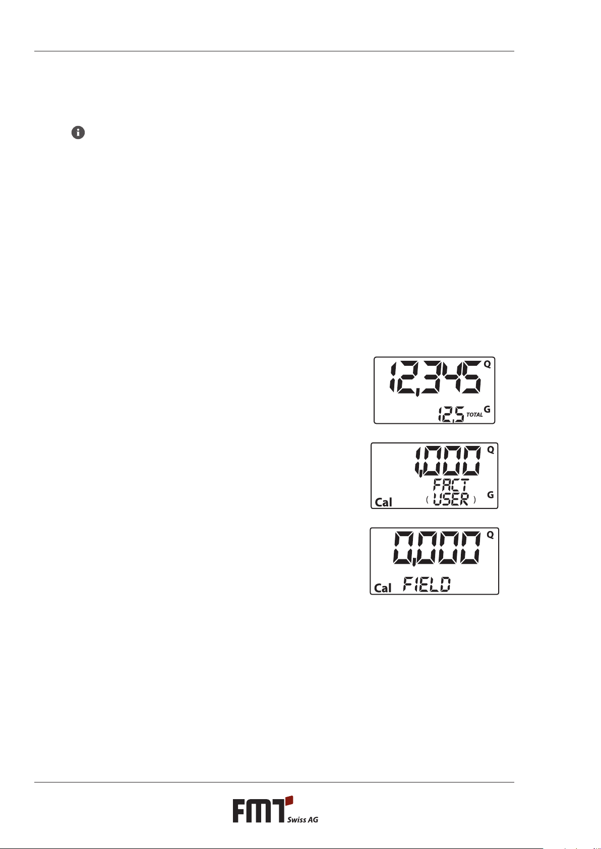
Go to default standby mode. Press the TOTAL button. The display shows the valid calibration factor.
Two situations are possible:
a) User never changed the calibration factor and/or user restored the factory calibration factor after
changing it: the display will show the following:
The word FACT (short for FACTORY) indicates that the valid calibration factor is the factor pre-set at the
factory.
b) If the user has changed the calibration factor, the display will show the new value
(in our example: 0.998)
The word USER indicates that the calibration factor currently used was entered by the user.
12
GOperating instructions for turbine ow meter
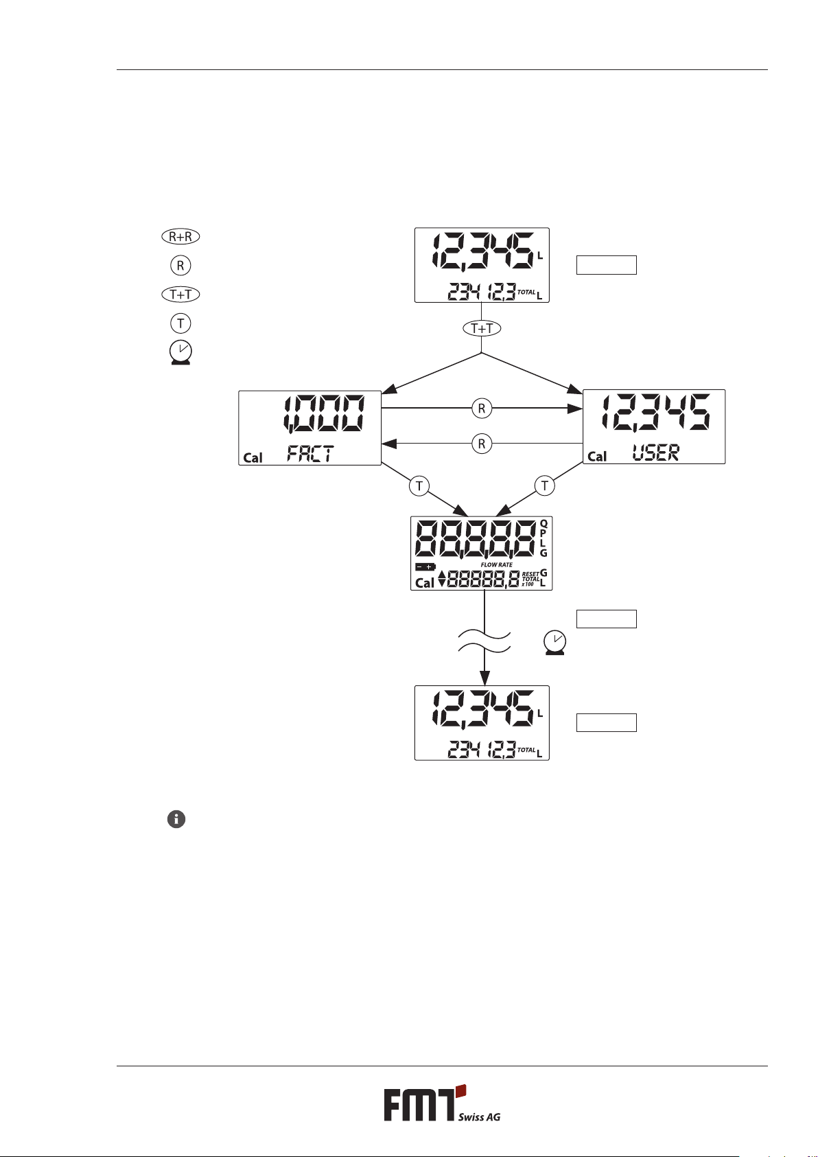
The ow chart below shows the schematics of the display modes the LCD display may go through.
In this mode, the user may press RESET and thus change from the USER to the FACTORY FACTOR .
In order to conrm your choice, shortly press TOTAL while the display shows either USER or FACT.
After re-start, the meter will use the new calibration factor you just conrmed.
Tip
When you conrm restoration of the Factory K Factor, the old user factor will be deleted from
memory.
Standby
Standby
Standby
Reset long
Reset short
Total long
Total short
Time OL 1
Key
13
Operating instructions for turbine ow meter G
6.3.2 Calibration during simulated operation
This procedure is basically a simulated output of liquid into a calibration vessel under actual operating
conditions (ow, rate, viscosity etc.). The procedure must be carried out with utmost care.
Tip
Absolutely bear in mind the following points in order to guarantee proper calibration:
Have your equipment properly vented before calibration.
Use a calibrated vessel holding at least 5 litres with a precise full mark.
For calibration, tap a certain amount of test liquid with a constant ow rate, exactly as you
would do in normal operation. Continue until the vessel is full.
Do not decrease the ow rate when you approach the full mark. Instead, turn the spigot on
and o and ll the vessel in small batches, but make sure the ow rate remains unchanged.
When you‘re nished be sure to wait a few minutes and let air bubbles escape that may still be
in the calibration vessel. Otherwise there is a danger you get a wrong value because the level
in the vessel may still go down.
Be sure to carry out the following procedure correctly.
6.3.3 Meter calibration during simulated operation
Action DISPLAY
1 NONE
Meter is in default standby mode, not counting
2 PRESS TOTAL SEVERAL SECS
Meter switches to calibration mode, displaying TOTAL.
Display no longer shows total volume, but instead the valid
calibration factor. FACT and USER indicate whether valid
calibration factor is FACTORY K FACTOR or USER K FACTOR .
3 PRESS RESET SEVERAL SECS
Meter shows TOTAL display and the resettable total register
displays zeroes. Meter is now ready for simulated operation
calibration.

14
GOperating instructions for turbine ow meter
4 FILL LIQUID INTO CAL VESSEL
Start simulated operation, but do not press any buttons
yet.
Simulated operation may be interrupted and continued
as necessary. Continue lling the vessel until full mark is
reached. It is not necessary to top out at any specic value.
Set value Actual value
5 PRESS RESET SHORTLY
This is how the meter‚knows‘ that sim op for calibration is
complete. Make sure cal vessel has really been lled up to
full mark before you do this.
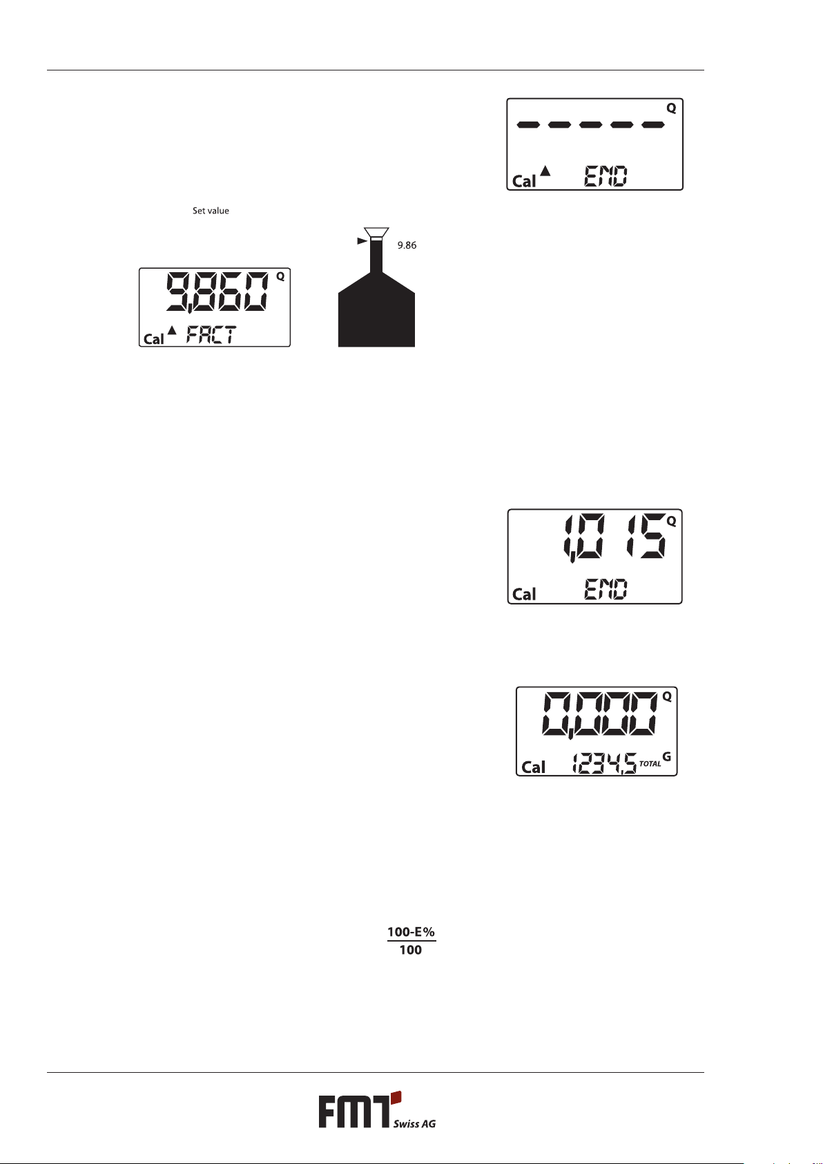
For calibration you must correct the count indicated by
the partial volume register (ex.: 9,800), entering the actual
value, i.e. the volume of the cal vessel. An arrow at the
bottom left of the display (pointing up or down) indicates
the direction in which USER K FACTOR is changed. Increase
or decrease when actions 6 or 7 are carried out.
6PRESS RESET SHORTLY
Direction of arrow ips. This may be repeated as often as
necessary.
7PRESS TOTAL SHORTLY / SEVERAL SECS
Value indicated will change as indicated by arrow:
One increment per each time TOTAL is pressed
Continuous if the TOTAL button is held down, the rst 5
increments slow, then fast.
If you overshoot, go back to point 6 and repeat (6).
15
Operating instructions for turbine ow meter G
8PRESS RESET SEVERAL SECS
This is how the meter‚knows‘ that calibration is now
complete.
Before you press the button, be absolutely sure the
display shows the correct value (volume of vessel).
Actual value
The meter will now calculate the new USER K FACTOR: This
may take a couple of secs. depending on the complexity of
the correction. The arrow will disappear during this phase,
but the word TOTAL will remain unchanged.
If you carry out this action right after point 5 the new USER
K FACTOR will be equal to the FACTORY K FACTOR. It will be
ignored, therefore.
9NONE
After completion of the calculation the new USER K
FACTOR will be displayed a few seconds. Next, the meter
will re-start. Finally, the meter will be back in default
standby mode.
PLEASE NOTE: From now on, the new value set will be
used as the new valid K Factor and will remain even
after replacement of batteries!
10 NONE
The meter stores the new K Factor for operation and is now
ready for serious operation using the newly set USER K
FACTOR.
6.3.4 Changing the K FACTOR directly
This procedure is helpful for the correction of a mean error that may occur as a result of many output
operations. In the event you observe a mean percentage error during normal meter operation you may
carry out a correction by changing the valid User K Factor by that percentage. In order to calculate the
correction of the USER K FACTOR, proceed as follows:
New calibration factor = old calibration factor x

16
GOperating instructions for turbine ow meter
Example:
Observed mean percentage error E % -0,9 %
Current K Factor 1.000
New USER K FACTOR 1.000 x 100-(-0,9)÷100=
1.000 x (100+0,9)÷100=
1.009
If the meter displays less than the actual amount of liquid output (negative error), the new K Factor must
be greater than the old one (see example). The opposite is true if the value indicated is greater than the
actual amount (positive error).
Action DISPLAY
1 NONE
Meter is in default standby mode, not counting
2 PRESS TOTAL SEVERAL SECS
Meter changes to calibration mode displaying the valid K
Factor instead of the partial volume. FACT or USER indicates
whether valid calibration factor is Factory K Factor or User
K Factor .
3 PRESS RESET SEVERAL SECS
Meter shows TOTAL display and the resettable total register
displays zeroes. Meter is now ready for simulated operation
calibration.
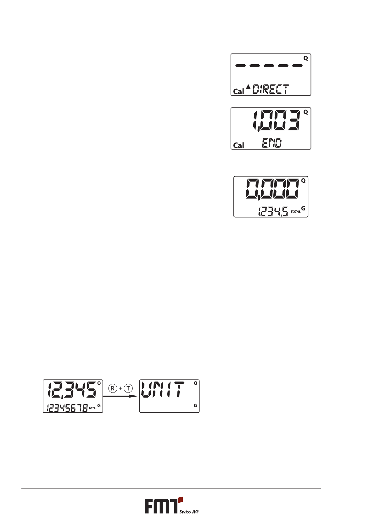
4 PRESS RESET SEVERAL SECS
Changing valid K Factor directly: The word DIRECT is dis-
played, together with the calibration factor currently in use.
An arrow at the bottom left of the display (pointing up or
down) indicates the direction in which the displayed value
is changed. Increase or decrease when actions 5 or 6 are
carried out.
5 PRESS RESET SHORTLY
Direction of arrow ips. This may be repeated as often as
necessary in order to set the correct direction.
6 PRESS RESET SHORTLY / SEVERAL SECS
Value indicated will change as indicated by arrow.
One increment per each time TOTAL is pressed.
Continuously if TOTAL is held down. Display will‚roll‘
more quickly if button is held permanently.
If you overshoot, go back to point 5 and repeat.
17
Operating instructions for turbine ow meter G
7 PRESS RESET SEVERAL SECS
This is how the meter‚knows‘ that calibration is now com-
plete.
Before you press this button, be absolutely sure the
value indicated is the value you wanted to set.
8 NONE
After the following calculation the new USER K FACTOR will
be displayed a few secs. Next, the meter will re-start. Finally,
the meter will be back in default standby mode.
PLEASE NOTE: From now on, the new value set will be
used as the new valid K Factor and will remain even
after replacement of batteries.
9 NONE
The meter stores the new K Factor for operation and is now
ready for serious operation using the newly set USER K
FACTOR.
7. Conguration of the turbine ow meter
The turbine ow meter has a menu to assist users in the selection of the main unit of measure: quarters
(QTS), pints (PTS), litres (L), gallons (GAL).
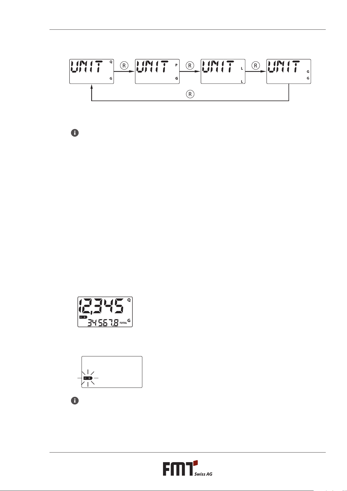
Combining partial-volume and total-volume units is possible as shown in the following table:
Combination no. Unit Register
of partial amounts
Unit Register
of total amounts
1 litres (L) litres (L)
2 gallons (GAL) gallons (GAL)
3 quarters (QTS) gallons (GAL)
4 pints (PTS) gallons (GAL)
This is how you select any of the combinations proposed:
Wait until the meter is in default standby mode. Simultaneously press TOTAL and RESET until the
display shows the word„UNIT“ displaying the valid unit being used at present
(in our example: litres/litres).
18
GOperating instructions for turbine ow meter
Every time you (shortly) press RESET, one of the other combinations of units will be displayed one after the
other (see gs.):
Press TOTAL for several seconds to store the new combination. The meter will re- start and is then ready
for operation using the newly selected combination of units.
Tip
The registers of the resettable and non-resettable totals will automatically switch over to the new
units set.
You do NOT have to re-calibrate after changing the units.
8. Service
This turbine ow meter has been designed for minimum maintenance requirements. What remains to be
done from time to time:
Exchange the batteries when discharged.
Clean the measuring chamber. This may be necessary from time to time depending on the specic
liquid(s) being measured and/or when foreign matter gets into the chamber (inlet lter not sucient).
8.1 Exchanging batteries
The meter is supplied complete with two 1.5 V alkaline batteries (1N).
The meter has a two-step low battery indicator:
1) As soon as the batteries dip below the rst charge level the battery icon in the display will light up.
The meter will continue to operate correctly, but the user is informed that the batteries should be
exchanged as soon as possible.
2) If the batteries are not exchanged, the battery will sooner or later reach the second alarm level. Normal
operation is no longer possible. At this state, the battery icon will ash, being the only thing that is still
visible in the display.
Tip
Do not throw batteries in the dustbin. Be sure to know and respect local regulations concerning
proper disposal.

19
Operating instructions for turbine ow meter G
Proceed as follows (items correspond to spare parts list):
Press RESET in order to update total volume.
Unscrew the battery cover (item 8).
Remove the old batteries.
Insert new batteries. Observe + and - icons on batteries and cap (item 1).
Replace battery cap properly and screw down tightly. Make sure the seal (item 7) and spring (item 9)
are in their correct positions.
The meter will go on automatically and revert to default standby mode. Routine operation may now be
continued.
The values of the resettable and non-resettable totals and partial volume will be the same as before.
Neither will the calibration (K) factor change in the case of power failures and/or exchange of batteries. It is
not necessary to re-calibrate the meter after exchange of batteries.
8.2 Cleaning
The measuring chamber of the turbine ow meter can be cleaned only after disconnecting the meter from
the pipeline or spigot. The inlet and outlet must be fully accessible.
Tip
Always make sure that ALL the liquid has been removed from the device before you start cleaning
it.
The turbine ow meter has no lter that needs to be cleaned. Therefore, it is only possible to determine
at the inlet and outlet whether large particles have gotten caught in the meter. If there are any foreign
objects in the meter, they can be removed with a pointed object, such as a small screwdriver, or needle
nose pliers.
Caution!
Never blow compressed air into the meter, since the resulting high speed of rotation can cause the
magnets to become loose!
After removing larger objects, a suitable liquid can be used to rinse out smaller foreign particles. It is best
to use diesel fuel or heating oil for this.
Be careful not to damage the body of the device and the plastic parts.
9. Troubleshooting
Problem Cause Solution
LCD display: No display Loose battery contact Check batteries for good contact
Accuracy of measurements is
insucient
K FACTOR wrong
Meter operates below admissible
min. ow rate
Check K FACTOR (section 6.3)
Increase ow rate to acceptable
level
Reduced ow rate, no ow at all Turbine blocked Clean measuring chamber
Display ashing„Err 1“ Data stored in electronic memory
are damaged
Sorry, irreparable
Short display of„Err 2“ Limited error reading data (usu-
ally when exchanging batteries)
Control circuit board automa-
tically switches on and o to
restore proper operation

20
GOperating instructions for turbine ow meter
10. Repairs/service
This turbine ow meter has been designed and built in compliance with the highest quality standards.
If a problem should occur despite all quality measures taken, please get in touch with our service
contact partners:
FMT Swiss AG
Tel +49 9462 17-216
Fax +49 9462 1063
11. Manufacturer‘s declaration
We hereby state that the equipment described below, in the model which we have made commercially
available, complies in its design and construction with the applicable requirements. If the equipment is
used other than for its intended purpose, this declaration loses its validity.
Designation of the appliance Turbine ow meter
Complies with EU directive: 89/336/EEC (EMC directive) and pertinent amendments.
Relevant EU standards: EN 61000-6-1
EN 61000-6-3
EN 55014-1-2000
EN 55014-2-97
24.09.2012 FMT Swiss AG
Dipl.-Ing. Rudolf Schlenker
Table of contents
Other FMT Swiss AG Measuring Instrument manuals


Popular Measuring Instrument manuals by other brands


Extech Instruments
Extech Instruments SDL470 user manual

Rohde & Schwarz
Rohde & Schwarz ZNL4 user manual

HB Ross Manufacturing Co.
HB Ross Manufacturing Co. ACVGD ROSS METER user manual

Polimaster
Polimaster PM1703MO-1 Operation manual

Agilent Technologies
Agilent Technologies U4154A Service guide

Santec
Santec TSL-550 Operation manual


