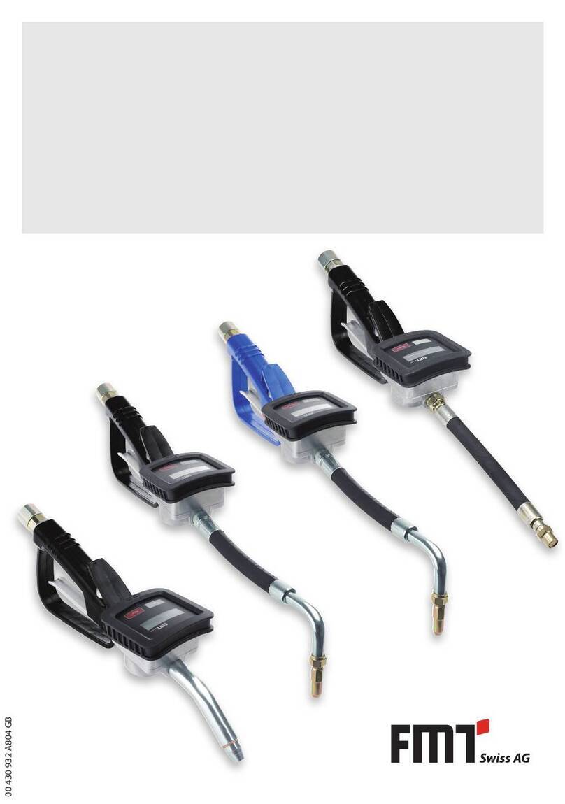
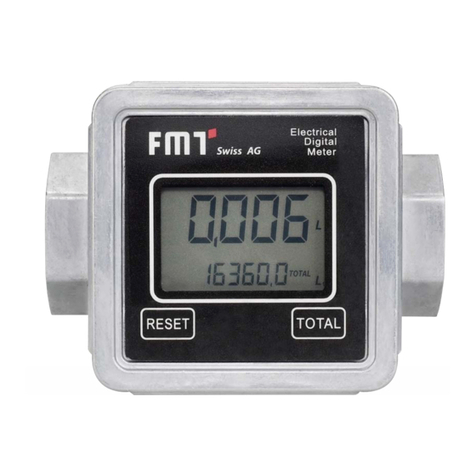
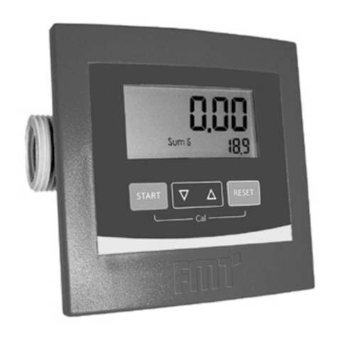
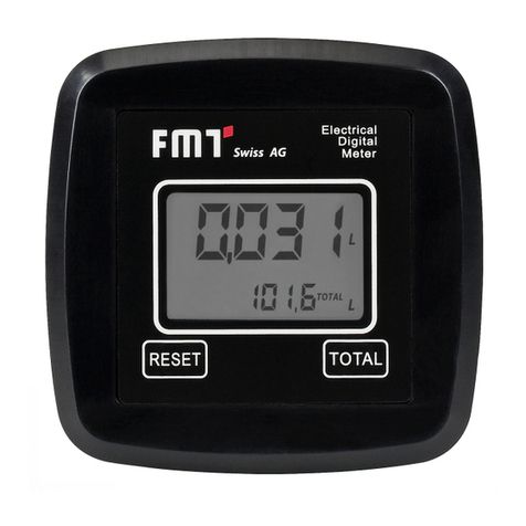
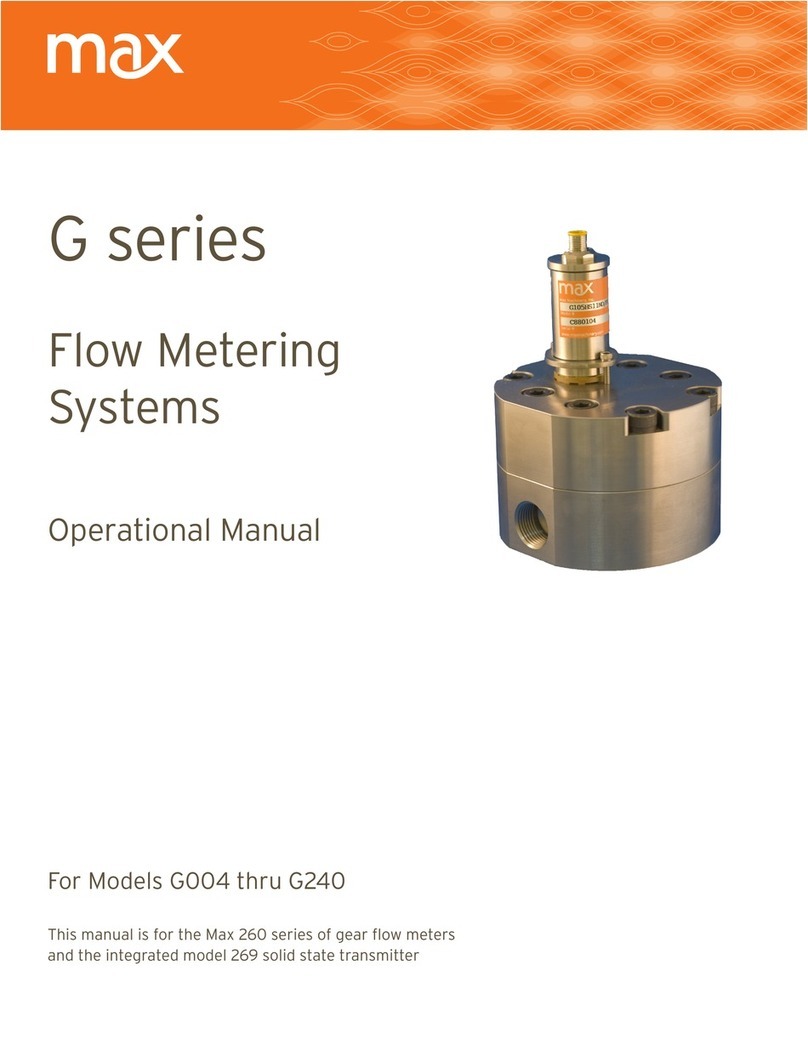
FMT Swiss AG 23 829 Instruction Manual

OPERATING INSTRUCTIONS
AND SAFETY NOTES
NUMERIxx3 oval gear meter
2 - 100 l/min
Pulse meter IPG
82 363 006 A803 US

2
US Operating instructions - digital oval gear meter and pulse meter
FMT Swiss AG
This documentation is exclusively intended for the operating company and their sta.
Without our written consent, the content of this documentation (textes, gures, drawings, charts,
diagrams etc. ), must not be duplicated or distributed, neither in full or in part, utilized for the purpose
of competition or passed on/made availabe to third parties.
FMT Swiss AG
Fluid Management Technologies Swiss AG
Gewerbestraße 6
6330 Cham / Schweiz
Phone: +41 41 712 05 37
Fax: +41 41 720 26 21
Email: info@fmtag.com
Internet: www.fmtag.com
Operating instructions translation
Date of issue: 01/2017
We reserve the right to make design and product modications, which serve to improve the product.

3
Operating instructions - digital oval gear meter and pulse meter US
Table of Contents
1. Introduction ________________________________________________________________________4
1.1 Preface ____________________________________________________________________________4
1.2 Obligations of the personnel ___________________________________________________________4
1.3 Symbols in this manual _______________________________________________________________4
1.3.1 Structure of the warning notes _________________________________________________________4
1.3.2 Hazard warning symbols ______________________________________________________________5
1.3.3 General symbols _____________________________________________________________________5
2. Safety notes ________________________________________________________________________5
2.1 Authorized personnel_________________________________________________________________6
2.2 Risks when handling the oval gear meter _________________________________________________6
3. Intended conditions of use ____________________________________________________________6
3.1 Design and functional description ______________________________________________________6
3.1.1 LCD display _________________________________________________________________________7
3.1.2 User controls________________________________________________________________________8
3.1.3 Measuring chamber __________________________________________________________________8
3.1.4 Battery compartment_________________________________________________________________8
4. Technical data_______________________________________________________________________9
5. Assembly__________________________________________________________________________10
6. Installation ________________________________________________________________________10
7. Routine operation __________________________________________________________________11
7.1 Output of liquid during standard operation (Normal Mode) _________________________________11
7.1.1 Resetting partial volumes ____________________________________________________________12
7.1.2 Resetting the resettable total volume (RESET TOTAL)_______________________________________12
7.2 Output of liquid with display of current ow rate (Flow Rate Mode)___________________________13
7.2.1 Resetting partial volumes ____________________________________________________________13
8. Calibration ________________________________________________________________________14
8.1 Denition _________________________________________________________________________14
8.2 Why calibrate? _____________________________________________________________________14
8.3 Calibration mode ___________________________________________________________________14
8.3.1 Displaying the valid calibration factor- resetting the factory calibration factor (if necessary) ______15
8.3.2 Calibration during simulated operation _________________________________________________16
8.3.3 Meter calibration during simulated operation ____________________________________________17
8.3.4 Changing the K FACTOR directly _______________________________________________________20
9. Conguration of the meter ___________________________________________________________21
10. Maintenance_______________________________________________________________________22
10.1 Exchanging batteries ________________________________________________________________22
10.2 Cleaning __________________________________________________________________________23
11. Troubleshooting ___________________________________________________________________24
12. Repairs/service _____________________________________________________________________24
13. Disposal___________________________________________________________________________24
14. EC Declaration of Conformity _________________________________________________________25
15. Exploded view and mounting dimensions pulse meter and digital oval gear meter without display _______26
16. Exploded view and mounting dimensions pulse meter and digital oval gear meter with display__________28

4
US Operating instructions - digital oval gear meter and pulse meter
1. Introduction
1.1 Preface
Please carefully read these operating instructions and observe in particular all safety notes!
Our sta will be pleased to provide support if you have any questions about the product.
Yours sincerely, FMT Swiss AG
1.2 Obligations of the personnel
Before they start to work, all persons who are entrusted with work with the oval gear meter, are obliged:
– to follow all applicable regulations on occupational safety and accident prevention.
– to read and to comply with all safety instructions and warning notes contained in these operating
instructions.
Please observe the following instructions in the interest of all concerned:
Refrain from any unsafe working methods!
Adhere to all hazard and warning notes contained in this manual!
In addition to this documentation, keep to all generally accepted safety rules, legal provisions as
well as all other binding rules regarding occupational safety, accident prevention and environmental
protection!
Wear appropriate protective clothing in accordance with the work to be done!
Perform only work for which you have been suciently trained and instructed!
Only genuine spare parts as well as original tools and auxiliaries of the manufacturer are allowed to be
used in order to ensure the functional safety and maintain the warranty coverage.
1.3 Symbols in this manual
1.3.1 Structure of the warning notes
The warning notes have the following structure:
SIGNAL WORD
Type and source of the hazard
Consquences of non-compliance with the notes
Measures to avoid that risk
Depending on the danger level, dierent signal words are used
SIGNAL
WORD
Danger level Consequences of non-compliance
DANGER Imminent threat
of danger
Death or serious bodily injury
WARNING Possible threat
of danger
Death or serious bodily injury
CAUTION Possibly dangerous
situation
Minor bodily injury
ATTENTION Possibly dangerous
situation
Damage to material property

5
Operating instructions - digital oval gear meter and pulse meter US
NOTE
Indicates further information or tips which facilitate work.
1.3.2 Hazard warning symbols
Symbol Meaning
General hazard symbol. The warning note marked in this way contains
supplementary information on the type of hazard.
This symbol warns of dangerous electrical voltages.
This symbol warns of a hazardous explosive atmosphere.
1.3.3 General symbols
Symbol Meaning
A small black square indicates the work you have to perform.
–The dash denotes lists.
aThe arrow identies cross-references.
If cross-references to other chapters are required within the text, the expression
is shortened for reasons of clarity.
Example: aChapter 2 Safety notes
This means: please refer to chapter 2 for the safety notes
2. Safety notes
Various dangers may occur if the oval gear meter is improperly handled during installation, commissio-
ning and daily operation.
WARNING
Risk of injury and damage to material property because of improper handling!
Hold the manual at the disposal of the operating sta at the usage site of the unit.
Country-specic safety measures and accident prevention regulations must
be observed.

6
US Operating instructions - digital oval gear meter and pulse meter
2.1 Authorized personnel
Only qualied and authorized persons are allowed to operate and to work on the oval gear meter.
Persons are qualied if they are, due to their training, experience, instruction and knowledge of the
relevant standards, able to assess assigned tasks and to identify potentially hazardous situations.
These persons must have been authorized by the person responsible for the safety of the unit and must
be able to identify and to avoid potential dangers.
All persons charged with installation, operation, maintenance and repair work, must have read and
understood this operation manual.
A copy of this operating manual must be stored permanently and ready at hand at the place of usage
of the unit.
2.2 Risks when handling the oval gear meter
CAUTION
The oval gear meter is only suited for use with hardly inammable media.
The oval gear meter is not allowed to be used in potentially explosive
environments.
NOTE
Particular mention must be given to §19g of the German Water Resources Act
(WHG) which requires that lling facilities must be designed, installed, positioned,
maintained and operated in such a way so as to ensure that no water pollution or
other undesirable alterations of water properties occur.
According to §19i WHG, the operator of such an installation is obliged to monitor
permanently the compliance with the aforementioned requirements for the
installation location.
3. Intended conditions of use
This oval gear meter has been designed and developed for the precise measurement and registration
of volumes of varous media featuring dierent viscosities such as DEF, diesel and heating oil.
3.1 Design and functional description
The oval gear meter/pulse meter is a uid meter with electronic counter and digital display.
The medium owing through the meter sets a oval gear in rotation. The revolutions of the gears are
converted into electronic pulses and sent to the electronic counter by a Reed switch. The electronics,
nally, uses a certain multiplication factor to convert the pulses into an intelligible volume of liquid
having gone through the device, which is then shown on the LCD display.
The multiplication factor has been pre-set at the factory using an average that has turned out to be
useful in normal operation. However, it can be easily adapted to specic requirements by the user.
The total volume measured is stored and can be called up by pressing the TOTAL button.
The user needs only two membrane key switches for operation: RESET and TOTAL (total volume).
The body of the device is made of aluminium. (DEF version made of stainless steel).

7
Operating instructions - digital oval gear meter and pulse meter US
MEASURING
CHAMBER
RESET BUTTON
LCD DISPLAY
TOTAL BUTTON
The electronic components and LCD display sit at the top of the oval gear meter, well insulated against
the wet measuring chamber. There is a cover to protect them against the working environment.
3.1.1 LCD display
The meter‘s LCD display is equipped with two numeric registers and dierent types of display modes
showing information to the user only when it is actually needed with the operation / function going on
at the moment.
Key:
1. Register of partial volume (5 digits with oating decimal: 0.000+99999) showing the amount of liquid
that has been delivered since the RESET button was last pressed
2. Battery charge
3. Display of the calibration mode
4. Register of total volume (6 digits with oating decimal 0.0-999999x10/x100) showing two dierent
kinds of total volumes:
4.1 Non-resettable total volume (TOTAL)
4.2 Resettable total volume (RESET TOTAL)

8
US Operating instructions - digital oval gear meter and pulse meter
5. Total volume multiplication factor (x10/x100)
6. Type of total volume display (TOTAL/RESET TOTAL)
7. Units for total volume; L=litres; GAL=gallons
8. Flow rate display
9. Display of measuring unit for partial volumes:
QTS=quarters; PTS=pints; L=litres; GAL=gallons;
The display can be adapted to the direction of ow in 90° steps. To do so (refer to g. 16-1; item 4),
loosen the four screws . Now you can mount the display unit turned by 90°.
CAUTION
Take care to ensure that the cables from the battery holder kit (refer to g. 16-1,
item 21) to the board (g. 16-1, item 17) are not pinched or excessively twisted.
Then, re-insert and tighten the screws (refer to g. 16-1, item 4).
3.1.2 User controls
There are two push buttons on the meter (RESET and TOTAL), each controlling two main functions
(pressed individually) and various auxiliary sub-functions (pressed simultaneously).
Main functions:
RESETT button: Resetting the partial volume register and the (resettable) total volume register
RESET TOTAL.
TOTAL button: Calling up the calibration mode. Pressed together, the two buttons call up the
conguration mode where you select the unit of measurement.
3.1.3 Measuring chamber
The measuring chamber is located in the centre of the meter.
There is a oval gear in the measuring chamber, set in rotation by the ow of liquid. Each revolution will
generate an electrical pulse that is processed by the microprocessor on the control circuit board.
The microprocessor uses a calibration factor (i.e. a‚weighting‘ assigned to each pulse) to convert the
pulses generated by the gears‘ revolutions into an intelligible value representing the volume of liquid
that has passed through. It is then displayed in the unit pre-set before in the corresponding registers of
the LCD display for partial and total volumes, respectively.
All of our oval gear meters leave the factory with a default calibration factor = 1000 called„FACTORY
K FACTOR“. There is a possibility to calibrate the meter in order to adapt that factor to the physical
properties of dierent liquids.
There is always a possibility to return to the manufacturer‘s default setting.
3.1.4 Battery compartment
The meter is powered by two 1.5 V standard batteries (N1).
The battery compartment is inside the body. To replace the batteries, you must remove the cover.

9
Operating instructions - digital oval gear meter and pulse meter US
4. Technical data
Designation NUMERIxx³
Diesel
23 190
Pulse meter
Oval gear meter
with display
Diesel
23 829
Pulse meter
Oval gear meter
without display
Diesel
23 820
Measuring system oval gear oval gear oval gear
Distance in-/out ange (inch) 3.74 3.74 3.74
Connection on both ends G 1‘‘ f G 1‘‘ f G 1‘‘ f
Media diesel, heating oil diesel, heating oil diesel, heating oil
Flow capacity (gpm) 0.53-26.42 0.53-26.42 0.53-26.42
Pre-set ow direction horizontal horizontal horizontal
Permitted liquid temperature max. (°F) 104 104 104
Permitted ambient temperature (°F) 14 / 140 14 / 140 14 / 140
Measuring tolerance (%) 0,5 0,5 0,5
Nominal pressure (psi) 50 50 50
Burst pressure (psi) 400 400 400
Impulses (pulses/gal) 12.15 12.15
Contact form A-closer A-closer
Switching capacity (W) 10 10
Operating voltage (V) 3-30 V DC 3-30 V DC
Operating current (A) 0,5 0,5
Switch current (A) 0,5 0,5
Sensor resistor (mOhm) 300 300
Material housing aluminium aluminium aluminium
External dimensions LxWxH (inch) 3.94 x 3.94 x 2.56 3.94 x 3.94 x 2.56 3.94 x 3.94 x 2.56
Weight (lb) 1.28 1.43 1.43
Tab. 4-1: Technical data oval gear meter diesel

10
US Operating instructions - digital oval gear meter and pulse meter
Designation NUMERIxx³
DEF
23 190 870
Pulse meter
Oval gear meter
with display
DEF
23 829 870
Pulse meter
Oval gear meter
without display
DEF
23 823 006
23 823 066
Measuring system oval gear oval gear oval gear
Distance in-/out ange (inch) 3.74 3.74 3.74
Connection on both ends G 1‘‘ f G 1‘‘ f G 1‘‘ f
Media DEF DEF DEF
Flow capacity (gpm) 0.53-26.42 0.53-26.42 0.53-26.42
Pre-set ow direction horizontal horizontal horizontal
Permitted liquid temperature max. (°F) 95 95 95
Permitted ambient temperature (°F) 23 / 95 23 / 95 23 / 95
Measuring tolerance (%) 0,5 0,5 0,5
Nominal pressure (psi) 50 50 50
Burst pressure (psi) 400 400 400
Impulses (pulses/gal) 12.15 12.15
Contact form A-closer A-closer
Switching capacity (W) 10 10
Operating voltage (V) 3-30 V DC 3-30 V DC
Operating current (A) 0,5 0,5
Switch current (A) 0,5 0,5
Sensor resistor (mOhm) 300 300
Material housing stainless steel stainless steel stainless steel
External dimensions LxWxH (inch) 3.94 x 3.94 x 2.56 3.94 x 3.94 x 2.56 3.94 x 3.94 x 2.56
Weight (lb) 2.31 2.31 2.31
Tab. 4-2: Technical data oval gear meter DEF
5. Assembly
The oval gear meter comes pre-assembled and ready to go.
According to the version, accessories may be or must be mounted.
NOTE
Ensure cleanliness during installation and an exact connection and
accurate sealing.
6. Installation
The inlet and outlet of the oval gear meter are aligned in a straight axis and equipped with 1“ threads.
The meter may be installed in any given position, as a xed unit in a pipeline and/or as a mobile unit on a
spigot.
The oval gear meter does not have a pre-dened ow direction. Both ends may alternatively serve as
inlet or outlet, as needed. However, it is absolutely important that the side that is used as inlet (where the
pipeline arrives) is equipped with a lter with suitable performance characteristics. Solid particles getting
into the measuring chamber might clog up the ovar gear.

11
Operating instructions - digital oval gear meter and pulse meter US
7. Routine operation
The turbine ow meter comes pre-assembled and ready to go.
Even after periods of prolonged storage, it will be ready for operation without any lengthy preparations.
The only action that may be necessary from time to time during normal operation is to reset the registers
of partial and/or resettable total volumes.
To accomplish that, call up the two displays for normal operation. The rst normal operation display
contains the partial volume and resettable total volume (RESET TOTAL). The other display shows the
partial volume and the non-resettable (absolute) TOTAL volume. The LCD automatically switches between
resettable and absolute total in a given period of time. This has been set at the factory and cannot be
inuenced by the user.
RESETTABLE
TOTAL VOLUME
register
ABSOLUTE
VOLUME
register
PARTIAL VOLUME register
The register of the absolute total (TOTAL) cannot be reset by the user. It will continue counting during the
entire lifetime of the meter. The resettable and non-resettable registers of total volumes (RESET TOTAL and
TOTAL) share the same‚window‘ and the same digits of the LCD display. For that reason, the two numbers
cannot be viewed at the same time.
The oval gear meter has been programmed so that the one or the other total is visible at certain moments /
in certain modes during operation (never both at a time):
The absolute total volume (TOTAL) is visible in standby mode.
The resettable total (RESET TOTAL) is visible at the following times / in the following modes:
- For a short moment (several seconds) after resetting the (resettable) partial volume.
- During the output of liquid.
A few seconds after output of the liquid this short time span expires and the meter switches to standby
mode. The display of the bottom register shows the absolute total volume.
NOTE
For the display of total volumes, there are 6 digits available, plus two icons x10/x100.
The increments are activated in the following sequence:
0,0 ---> 99999,9 ---> 999999 ---> 100000 x10 ---> 999999 x10 ---> 100000 x100 --->
999999 x100
7.1 Output of liquid during standard operation (Normal Mode)
During standard output of liquid, the meter will count and at the same time display the volume having
gone through the device so far, and the resettable total (RESET TOTAL).
Accidental pressing of the RESET or TOTAL button does not have any eect in this state.

12
US Operating instructions - digital oval gear meter and pulse meter
A few seconds after uid discharge, the display of the lower register will change from resettable total to
absolute total: The word RESET above the word TOTAL will disappear, and the value of the resettable
total will be replaced by the absolute total.
We call this state (or mode)„standby“. It will persist as long as the user does not carry out any more actions
on the meter.
7.1.1 Resetting partial volumes
For resetting the partial volume register: Press the RESET button
while the meter is in standby, i.e. when you see the word TOTAL in
the display.
When you press RESET, the display will rst switch on all the
segments, one after the other, and then switch them all o again.
When the reset is complete, the display will rst show the partial
volume having been reset and then RESET TOTAL.
After a couple of seconds, RESET TOTAL will be replaced by the
NON-resettable total amount TOTAL.
7.1.2 Resetting the resettable total volume RESET TOTAL
You can reset the resettable total only if you have reset the
register of the partial volumes before. To reset the resettable total:
press RESET for several seconds. The display will show the words
RESET TOTAL (see g.):
You must carry out the following steps (in this order):
1. Wait until the display is back to default standby mode
(i.e. showing only TOTAL).
2. Press RESET shortly.
3. The meter will now start resetting the partial volume register.
4. While the display shows RESET TOTAL, press RESET again for at
least one second.

13
Operating instructions - digital oval gear meter and pulse meter US
5. The display will show all the segments again. Only then follows
the phase where all segments are switched o. Finally, there
will be a display showing the total that has been reset (RESET
TOTAL).
7.2 Output of liquid with display of current ow rate (Flow Rate Mode)
It is possible to output a liquid and have the following displays available at the same time:
Partial volumes having been output
Current ow rate (Flow Rate) in [unit of partial volume per min.], as shown below.
This is how you get into this mode:
Wait until the meter is in default standby mode (i.e. the display shows only the total volume).
Press TOTAL shortly.
Start output operation.
The display of the current ow rate will be updated every 0.7 secs. For that reason the display may‚utter‘
somewhat with low ow rates. However, the higher the ow rate, the more stable the display will be.
NOTE
The current ow rate will be shown in the unit set for the partial volume register.
That means if partial and total volume have been set to dierent units (as shown in
the example below) you must bear in mind that the ow rate shown is in the unit
set for partial volumes. In the example shown, the ow rate is in QTS./min.
The word GAL next to the ow rate refers to the register of the (resettable and NON-resettable) total
volumes which will be displayed again as soon as you leave the ‚current ow rate‘ display mode.
In order to go back to the default standby mode, press the TOTAL button again.
Accidental pressing of the RESET or TOTAL button does not have any eect in this state.
NOTE
RESET TOTAL and absolute total (TOTAL) are not shown in this mode.
However, the values nevertheless go up. You can check after uid discharge.
Wait for the default standby mode and press TOTAL shortly.
7.2.1 Resetting partial volumes
In order to reset the partial volume register, you must rst complete the output of liquid. Wait until the
display shows a ow rate of 0.0 (see g.) and then press RESET shortly.

14
US Operating instructions - digital oval gear meter and pulse meter
The eect is dierent from what you would have if you press Reset in default standby mode. There is no
phase where all the segments are rst switched on and then o again. Instead, the register will display the
reset partial volume immediately.
8. Calibration
8.1 Denition
Calibration factor or„K FACTOR“:
This is the multiplication factor the system ascribes to the electronic pulses it receives in order to convert
them into a plain unit of measurement.
FACTORY K FACTOR: Calibration (default) factor pre-set at the factory. Factory K Factor = 1000.
This calibration factor ensures maximum precision under the following operating conditions:
Fluid Diesel DEF
Temperature 20 °C 20 °C
Flow rate 2-60 l/min 5- 30 l/min
You can always return to the original Factory K Factor even after you have changed the value. The
procedure is simple.
USER K FACTOR: This is the calibration factor the user has set to adapt the meter to specic
requirements (i.e. the user has carried out a calibration procedure).
8.2 Why calibrate?
The oval gear meter comes to you with a calibration factor pre-set at the factory that will guarantee the
most precise measurements under most operating conditions.
If calibration is necessary, it should be conducted under the operating conditions in which the meter is
used, such as in the following extreme conditions:
liquids having a viscosity close to the admissible limits (e.g. antifreeze with low viscosity, high-viscosity
oils for gearboxes)
extreme ow rates (i.e. close to upper or lower limits)
8.3 Calibration mode
The oval gear meter has a fast and precise electronic calibration mode where you simply change the
calibration factor (K FACTOR).
There are two calibration procedures you may choose from:
Calibration during simulated operation (requiring actual output of liquid to be carried out).
Direct calibration (simply changing the calibration factor).
You may want to call up the calibration procedure for the following reasons (press the TOTAL button for
several seconds):
To display the valid calibration factor
To reset the calibration factor pre-set at the factory (FACTORY K FACTOR) after calibration by the user
To change the calibration factor using one of the two available calibration procedures

15
Operating instructions - digital oval gear meter and pulse meter US
During calibration, the registers on the LCD display - that normally show partial and total volumes of liquid
output - will take on new meanings.
During calibration, the meter cannot carry out normal output operation.
During calibration, the count of the absolute total volume of liquid having been output (non-resettable
total) will not increase.
NOTE
The oval gear meter is equipped with a non-volatile memory so that saved
calibration data and the total output amount will be stored for prolonged periods
of time - even without power supply. That means you don‘t have to re-calibrate
after you have exchanged the batteries.
8.3.1 Displaying the valid calibration factor - resetting the factory calibration factor (if necessary)
Go to default standby mode. Press the TOTAL button. The display shows the valid calibration factor.
Two situations are possible:
a) User never changed the calibration factor and/or user restored the factory calibration factor after
changing it: the display will show the following:
The word FACT (short for FACTORY) indicates that the valid calibration factor is the factor pre-set at the
factory.
b) If calibrations have been made by the user, the calibration value currently used is indicated
(in our example 0,998).
The word USER indicates that the calibration factor currently used was entered by the user.
The ow chart below shows the schematics of the display modes the LCD display may go through.
In this mode, the user may press RESET and thus change from the USER to the FACTORY FACTOR.
In order to conrm your choice, shortly press TOTAL while the display shows either USER or FACT.
After re-start, the meter will use the new calibration factor you just conrmed.

16
US Operating instructions - digital oval gear meter and pulse meter
Standby
Standby
Standby
RESET long
RESET short
TOTAL long
TOTAL short
Time OL 1
Key
NOTE
When you conrm restoration of the Factory K Factor, the old user factor will be
deleted from memory.

17
Operating instructions - digital oval gear meter and pulse meter US
8.3.2 Calibration during simulated operation
This procedure is basically a simulated output of liquid into a calibration vessel under actual operating
conditions (ow, rate, viscosity etc.). The procedure must be carried out with utmost care.
NOTE
Absolutely bear in mind the following points in order to guarantee proper calibration:
Have your equipment properly vented before calibration.
Use a calibrated vessel holding at least 5 litres with a precise full mark.
For calibration, tap a certain amount of test liquid with a constant ow rate,
exactly as you would do in normal operation. Continue until the vessel is full.
Do not decrease the ow rate when you approach the full mark. Instead, turn
the spigot on and o and ll the vessel in small batches, but make sure the ow
rate remains unchanged.
When you are nished be sure to wait a few minutes and let air bubbles escape
that may still be in the calibration vessel. Otherwise there is a danger you get a
wrong value because the level in the vessel may still go down.
Be sure to carry out the following procedure correctly.
8.3.3 Meter calibration during simulated operation
Operation Display conguration
1 NONE
Meter is in default standby mode, not counting.
2 PRESS TOTAL SEVERAL SECS
Meter switches to calibration mode, displaying TOTAL.
Display no longer shows total volume, but instead the valid
calibration factor. FACT and USER indicate whether valid
calibration factor is FACTORY K FACTOR or USER K FACTOR.
3 PRESS RESET SEVERAL SECS
Meter shows TOTAL display and the resettable total register
displays zeroes. Meter is now ready for simulated operation
calibration.

18
US Operating instructions - digital oval gear meter and pulse meter
4 FILL LIQUID INTO CAL VESSEL
Start simulated operation, but do not press any buttons
yet.
Simulated operation may be interrupted and continued
as necessary. Continue lling the vessel until full mark is
reached. It is not necessary to top out at any specic value.
Set value Actual value
5 PRESS RESET SHORTLY
This is how the meter‚knows‘ that sim op for calibration is
complete. Make sure cal vessel has really been lled up to
full mark before you do this.
For calibration you must correct the count indicated by
the partial volume register (ex.: 9,800), entering the actual
value, i.e. the volume of the cal vessel. An arrow at the
bottom left of the display (pointing up or down) indicates
the direction in which USER K FACTOR is changed. Increase
or decrease when actions 6 or 7 are carried out.
6 PRESS RESET SHORTLY
Direction of arrow ips. This may be repeated as often as
necessary.
7 PRESS TOTAL SHORTLY / SEVERAL SECS
Value indicated will change as indicated by arrow
One increment per each time TOTAL is pressed.
Continuous if the TOTAL button is held down, the rst 5
increments slow, then fast.
If you overshoot, go back to point 6 and repeat (6).

19
Operating instructions - digital oval gear meter and pulse meter US
8 PRESS RESET SEVERAL SECS
This is how the meter‚knows‘ that calibration is now
complete.
Before you press the button, be absolutely sure the
display shows the correct value (volume of vessel).
Actual valueSet value
The meter will now calculate the new USER K FACTOR: This
may take a couple of secs. depending on the complexity of
the correction. The arrow will disappear during this phase,
but the word TOTAL will remain unchanged.
If you carry out this action right after point 5 the new USER
K FACTOR will be equal to the FACTORY K FACTOR. It will be
ignored, therefore.
9 NO OPERATION
After completion of the calculation the new USER K
FACTOR will be displayed a few seconds. Next, the meter
will re-start. Finally, the meter will be back in default
standby mode.
PLEASE NOTE: From now on, the new value set will be
used as the new valid K Factor and will remain even after
replacement of batteries!
10 NO OPERATION
The meter stores the new K Factor for operation and is now
ready for operation using the newly set USER K FACTOR.

20
US Operating instructions - digital oval gear meter and pulse meter
8.3.4 Changing the K FACTOR directly
This procedure is helpful for the correction of a mean error that may occur as a result of many output
operations. In the event you observe a mean percentage error during normal meter operation you may
carry out a correction by changing the valid User K Factor by that percentage. In order to calculate the
correction of the USER K FACTOR, proceed as follows:
New calibration factor = old calibration factor x
Example:
Observed mean percentage error E% -0,9 %
Current K Factor 1.000
New USER K FACTOR 1.000 x 100-(-0,9)÷100=
1.000 x (100+0,9)÷100=
1.009
If the meter displays less than the actual amount of liquid output (negative error), the new K Factor must
be greater than the old one (see example). The opposite is true if the value indicated is greater than the
actual amount (positive error).
Operation Display conguration
1 NONE
Meter is in default standby mode, not counting.
2 PRESS RESET SEVERAL SECS
Meter changes to calibration mode displaying the valid K
Factor instead of the partial volume. FACT or USER indicates
whether valid calibration factor is Factory K Factor or User
K Factor.
3 PRESS RESET SEVERAL SECS
Meter shows TOTAL display and the resettable total register
displays zeroes. Meter is now ready for simulated operation
calibration.
4 PRESS RESET SEVERAL SECS
Changing valid K Factor directly: The word DIRECT is dis-
played, together with the calibration factor currently in use.
An arrow at the bottom left of the display (pointing up or
down) indicates the direction in which the displayed value
is changed. Increase or decrease when actions 5 or 6 are
carried out.
5 PRESS RESET SHORTLY
Direction of arrow ips. This may be repeated as often as
necessary in order to set the correct direction.
This manual suits for next models
7
Table of contents
Other FMT Swiss AG Measuring Instrument manuals
