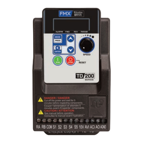
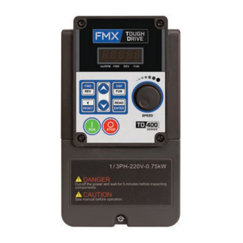
FMX TD 400 Series User manual


Table of Contents
Chapter 1: Safety Precautions
1.1 Before supplying Power to the AC Drive 1-1
1.2 Wiring 1-1
1.3 Before Operation 1-2
1.4 Auto Tuning 1-2
1.5 Operation 1-2
1.6 Maintenance, Inspection, and Replacement 1-3
1.7 Disposal of the AC Drive 1-3
1.8 UL Standards 1-4
Chapter 2: Model Description
2.1 Nameplate Data 2-1
2.2 Wire Gauge, Tightening Torque, Terminal, Short Circuit, Circuit Breaker, and Fuse Ratings 2-2
2.3 AC Drive Specifications 2-3
2.4 General Specifications 2-6
2.5 AC Drive Dimensions 2-7
Chapter 3: Environment and Installation
3.1 Environment 3-1
3.2 Installation 3-2
3.3 External View 3-3
3.4 Warning Labels 3-5
3.5 Removing the Front Cover 3-5
3.6 Wiring Peripheral Power Devices 3-6
3.7 General Wiring Diagram 3-8
3.8 Control Circuit Terminals and Jumpers 3-9
3.9 Power Terminals 3-10
3.10 AC Drive Wiring 3-11
3.11 Input Power and Motor Cable Length 3-12
3.12 Cable Length vs. Carrier Frequency 3-12
3.13 Installing an AC Line Reactor 3-12
3.14 Power Input Wire Size, and NFB 3-13
3.15 Control Circuit Wiring 3-13
3.16 AC Drive derating based on Carrier Frequency 3-13
3.17 Braking resistors 3-14
Chapter 4: User Interface and Programming
4.1 LED Keypad 4-1
4.1.1 LED Keypad Display and Keys 4-1
4.1.2 Display Description 4-2
4.1.3 LED Status Description 4-4
4.1.4 Operation Control 4-5
4.1.5 Using the Keypad 4-6
4.2 Parameter Summary 4-8
4.2.1: Parameter default values and ranges depending on AC Drive model 4-40
4.3 Parameter Details 4-42
Group 00 Basic Parameters 4-42
Group 01 V/F Control Parameters 4-52
Group 02 IM Motor Parameters 4-61
Group 03 External Digital Input and Output Parameters 4-65
Group 04 Analog Signal Inputs / Analog Output 4-87

Group 05 Preset Frequency Parameters 4-91
Group 06 Automatic Program Operation 4-95
Group 07 Start/Stop Parameters 4-99
Group 08 Protection Parameters 4-111
Group 09 Communication Parameters 4-120
Group 10 PID Parameters 4-121
Group 11 Auxiliary Parameters 4-130
Group 12 Monitoring Parameters 4-139
Group 13 Maintenance Parameters 4-142
Group 14 PLC Parameters 4-145
Group 15 PLC Monitoring Parameters 4-147
Group 16 LCD Function Group 4-148
Group 17 Automatic Tuning Parameters 4-152
Group 18 Slip Compensation Parameters 4-156
Group 20 Speed Control Parameters 4-159
Group 21 Torque Limit Parameters 4-163
Group 22 PM Motor Parameters 4-164
Chapter 5: Built-in PLC Function
5.1 Basic Command 5-1
5.2 Application Functions 5-3
5.2.1: Counter Function 5-3
5.2.2: Timer Function 5-5
5.2.3: Analog Comparator Function 5-8
5.2.4: Operation Control Function 5-9
5.2.5: Math Functions 5-10
Chapter 6: Communications
6.1 Modbus Protocol 6-2
6.1.1 Network Connection 6-2
6.1.2 Date Format Frame for ASCII Mode 6-3
6.1.3 Data Frame for RTU Mode 6-3
6.1.4 CRC 6-4
6.1.5 Register and Data Format 6-5
6.1.6 Monitor Data (Read-only) 6-6
6.1.7 Read holding Register [03H] 6-8
6.1.8 Loop Back Test [08H] 6-9
6.1.9 Write Single Holding Register [06H] 6-10
6.1.10 Write Multiple Holding Register [10H] 6-11
6.1.11 Modbus Addressing 6-12
6.2 BACnet Protocol Descriptions 6-20
6.2.1 BACnet Object Properties 6-21
Chapter 7: Troubleshooting, Fault Diagnostics and Maintenance
7.1 General 7-1
7.2 Fault Detection Function 7-1
7.3 General Troubleshooting 7-13
7.4 Troubleshooting Flowcharts 7-14
7.5 Routine and periodic inspection 7-20
7.6 Maintenance 7-22

1-1
1. Safety Precautions
1.1 Before supplying Power to the AC Drive
1.2 Wiring
Warning:
• To avoid the front cover disengaging or other physical damage, do not carry the AC Drive by its cover.
Support the unit by its heat sink when transporting. Improper handling can damage the AC Drive or injure
personnel and should be avoided.
• To avoid the risk of fire, do not install the AC Drive on or near flammable objects. Install on nonflammable
objects such as metal surfaces.
• If several AC Drives are placed inside the same control panel, provide adequate ventilation to maintain the
temperature below 50°C/122°F to avoid overheating or fire.
• When removing or installing the digital operator, turn off the power first and then follow the instructions in
this manual to avoid operator error or loss of display caused by faulty connections.
Warning:
MAIN CIRCUIT POWER SUPPLY TERMINALS MUST BE
CORRECTLY WIRED
Single Phase Input: L1(L) and L3(N)
Three Phase Input: L1(L), L2, and L3(N)
MOTOR CONNECTION ONLY: T1, T2, T3
(input power connection here will destroy the AC Drive)
Warning:
• Always turn OFF the power supply before attempting AC Drive installation and wiring of the user terminals.
• Installation and wiring must be performed by qualified personnel
• Properly ground the AC Drive and motor-side ground. Improper grounding could result in serious injury or
death from contacting the motor case.
• Grounding impedance: 240V class - less than 100Ω, 480V class - less than 10Ω
• Please check and test emergency stop circuits after wiring. (Installer is responsible for the correct wiring.)
• Never touch any of the input or output power lines directly or allow any input or output power lines to come
in contact with the AC Drive case.
• Do not perform a dielectric voltage withstand test (megger) on the AC Drive. This will result in AC Drive
damage to the semiconductor components.
• Check all wiring to ensure all connections are correct after installation of AC Drive and any other devices.
Failure to comply could result in serious injury, death, fire, or damage to the AC Drive.
Caution:
• Do not use an improper voltage source. Failure to comply could result in serious injury, death, fire, or
damage to the AC Drive. Verify the rated voltage of the AC Drive matches the voltage of the incoming
power supply before applying power.
• Tighten all terminal screws to the specified tightening torque. Loose electrical connections could result in
death or serious injury by fire due to overheating of electrical connections. (See Wire Gauge and Torque
Specification section 2.2)
• Never connect input power to the AC Drive output terminals T1, T2, T3.
• Do not connect a contactor or switch in series with the AC Drive and the motor.
• Do not connect a power factor correction capacitor or surge suppressor to the AC Drive output.
• Ensure the interference generated by the AC Drive and motor does not affect peripheral devices.
• Do not use unshielded cable for control wiring. Failure to comply may cause electrical interference resulting
in poor system performance. Use shielded twisted-pair wires and ground the shield to the ground terminal
of the AC Drive.

1-2
1.3 Before Operation
1.4 Auto-Tuning
1.5 Operation
Warning:
• Make sure the AC Drive capacity matches the parameter 13-00.
• Reduce the carrier frequency (parameter 11-01) if the cable from the AC Drive to the motor is greater than
80 ft (25m). A high-frequency current can be generated by stray capacitance between the cables and result
in an overcurrent trip of the AC Drive, an increase in leakage current, or an inaccurate current readout.
• Do NOT remove any protective covers or attempt any wiring while input power is applied. Connect all
power wiring and control wiring before applying input power. Always turn OFF the power supply before
attempting AC Drive installation and terminal wiring.
• Do not operate switches with wet hands. Electric shock may result.
• Do not touch any terminals before the capacitors have fully discharged. Internal capacitors hold a charge
after power supply has been removed. After disconnecting power, wait at least 10 minutes before touching
any wiring, circuit boards, or components. Check DC voltage between terminals B1/P or (+) and (-) does
not exceed 25V; otherwise, electric shock may result.
Caution:
• Do not connect a load to the motor while performing a rotational auto-tune.
• Make sure the motor can freely run and there is sufficient space around the motor when performing a
rotational auto-tune.
Warning:
• Do not connect or disconnect the motor during operation. This will cause the AC Drive to trip and may
cause damage to the AC Drive.
• Operations may start suddenly if an alarm or fault is reset with a run command active. Confirm that no run
command is active upon resetting the alarm or fault, otherwise accidents may occur.
• It provides an independent external hardware emergency switch which emergently shuts down the AC
Drive output in the case of danger.
• If automatic restart after power recovery (parameter 07-00) is enabled, the AC Drive will start automatically
after power is restored.
• Make sure it is safe to operate the AC Drive and motor before performing a rotational auto-tune.
• Do not touch AC Drive terminals when energized even if AC Drive has stopped, otherwise electric shock
may result.
• Do not remove covers or touch circuit boards while the power is on. Failure to comply could result in death
or serious injury.
• After the power is turned off, the cooling fan may continue to run for some time.
Caution:
• Do not touch heat-generating components such as heat sinks and braking resistors.
• Carefully check the performance of motor or machine before operating at high speed, otherwise injury may
result.
• Note the parameter settings related to the braking unit when applicable.
• Do not use the AC Drive braking function for mechanical holding, otherwise injury may result.
Warning:
This product is sold subject to IEC 61800-3. In a domestic environment this product may cause radio
interference in which case the user may need to apply corrective measures.

1-3
1.6 Maintenance, Inspection, and Replacement
Warning:
• Internal capacitors hold a charge after power supply has been removed. After disconnecting power, wait at
least 10 minutes before touching any wiring, circuit boards, or components. Check DC voltage between
terminals B1/P or (+) and (-) does not exceed 25V; otherwise, electric shock may result.
• Never touch high voltage terminals in the AC Drive.
• Make sure power to the AC Drive is disconnected before disassembling the AC Drive.
• Do not allow unqualified personnel to perform work on the AC Drive. Failure to comply could result in death
or serious injury. Installation, maintenance, inspection, and servicing must be performed only by authorized
personnel familiar with installation, adjustment, and maintenance of the AC Drive.
• Do not perform work on the AC Drive while wearing loose clothing, jewelry, or lack of eye protection. Failure
to comply could result in death or serious injury. Remove all metal objects such as watches and rings,
secure loose clothing, and wear eye protection before beginning work on the AC Drive.
• Observe proper electrostatic discharge (ESD) procedures when handling the AC Drive and circuit boards.
Failure to comply may result in ESD damage to the AC Drive circuitry.
• Do not modify the AC Drive circuitry. Failure to comply could result in damage to the AC Drive and will void
warranty. FMX is not responsible for any modification of the product made by the user. This product must
not be modified.
Caution:
• The AC Drive can be used in an environment with a temperature range from 14 -104°F (-10-40°C) and
relative humidity of 95% non-condensing.
• The AC Drive must be operated in a dust, gas, mist and moisture free environment.
1.7 Disposal of the AC Drive
Caution:
• Please dispose of this unit with care as an industrial waste and according to your required local regulations.
• The capacitors of AC Drive main circuit and printed circuit board are considered as hazardous waste and
must not be burned.
• The plastic enclosure and parts of the AC Drive such as the top cover board will release harmful gases if
burned.

1-4
vUL Standards
The UL/cUL mark applies to products in the United States and Canada and it means that UL has performed product
testing and evaluation and determined that their stringent standards for product safety have been met. For a product
to receive UL certification, all components inside that product must also receive UL certification.
UL/CUL Mark
v UL Standards Compliance
This AC Drive is tested in accordance with UL standard UL508C and complies with UL requirements. To ensure
continued compliance when using this AC Drive in combination with other equipment, meet the following conditions:
■ Installation Area
Do not install the AC Drive to an area greater than pollution severity 2 (UL standard).
■ Motor Over Temperature Protection
Motor over temperature protection shall be provided in the end use application.
■ Field Wiring Terminals
All input and output field wiring terminals not located within the motor circuit shall be marked to indicate the proper
connections that are to be made to each terminal and indicate that copper conductors rated 75°C are to be used.
■ AC Drive Short-Circuit Rating
This AC Drive has undergone the UL short-circuit test, which certifies that during a short circuit in the power supply the
current flow will not rise above value. Please see electrical ratings for maximum voltage and table below for current.
• Circuit protection must be installed before AC drive. See section 2.3 of the user manual for the appropriate circuit
breaker for your drive.
• Suitable for use on a circuit capable of delivering not more than (A) RMS symmetrical amperes for (HP) HP in 240 /
480 V class drives motor overload protection.
Horse Power ( HP ) Current ( A ) Voltage ( V )
1 - 50 5,000 240 / 480
51 - 200 10,000 240 / 480
vAC Drive Motor Overload Protection
Set parameter 02-01 (motor rated current) to the appropriate value to enable motor overload protection. The internal
motor overload protection is UL listed and in accordance with the NEC and CEC.
1.8 UL Standards

2-1
2. Model Description
2.1 Nameplate Data
Unpack the TD400 AC Drive and check the following:
(1) The TD400 AC Drive start-up and installation manual (this document) is contained in the package.
(2) The TD400 AC Drive has not been damaged during transportation; there should be no dents or missing parts.
(3) The TD400 AC Drive is the type you ordered. You can check the type and specifications on the main nameplate.
(4) Check that the input voltage range meets the input power requirements.
(5) Ensure that the motor HP matches the motor rating of the AC Drive.
(1HP = 0.746 kW)
Product Name and Motor Ra琀ng
Input Power Specifica琀ons
Output Power Specifica琀ons
Series No
UL and CE Marks
PRODUCT: E510-2P5-H-U MOTOR RATING: 0.5 HP
INPUT : AC 1/3PH 200-240V (+10%,-15%) 50/60hz 8.5/4.5A
OUTPUT : AC 3PH 0-599 Hz 3.1A IP20/NEMA 1
ENCLOSURE : IP20
P/N BARCODE S/N BARCODE
TD400-20P5-13PH
TD400 AC Drive Series
TD400 - 2010 - 1PH
20:
40:
200-240V
380-480V
Input Voltage Ra琀ng
Motor Ra琀ng
1:
13:
3:
1Ph
1Ph or 3Ph
3Ph
Input
P5: 0.5 HP
01: 1 HP
02: 2 HP
03: 3 HP
05: 5 HP
08: 7.5 HP
10: 10 HP
15: 15 HP
20: 20 HP
30: 30 HP
40: 40 HP
50: 50 HP
60: 60 HP
75: 75 HP

2-2
2.2 Wire Gauge, Tightening Torque, Terminal, Short Circuit, Circuit Breaker, and Fuse Ratings
Frame size AC Drive
HP
AC Drive
Voltage
Power Terminals Control Terminals
Maximum
Wire Size
Tightening Torque
Wire Range
Tightening Torque
kgf.cm lbf.in Nm kgf.cm lbf.in Nm
Frame 1
0.5–1 240 12 AWG
4mm² 10.2 8.9 1
30–12 AWG
0.05–4 mm² 4 3 0.4
1–2 480
Frame 2
2–5 240 8 AWG
10mm² 18.4 15.9 1.8
3–5 480
Frame 3
7.5–10 240 4 AWG
25mm² 24.5 21.2 2.4
7.5–15 480
Frame 4
15–20 240 4 AWG
25mm² 24.5 21.2 2.4
20–25 480
Frame 5
25 240 2 AWG
35mm² 25.5 22.1 2.5
30 480
Frame 6
30–40 240 3/0 AWG
95mm² 81.6 70.8 8
40–75 480
Notes:
• Wire size shown is based on maximum terminal size. Please consult the NEC or local codes for proper size to
be used.
• The wire size assumes a maximum voltage drop of 2%. If this value is exceeded, a larger diameter wire size may
be needed.
• Use only copper wires. Proper diameter wire should be based on ratings at 75°C.
• For safety reasons do not use under sized wiring.

2-3
Model TD400-20P5-13PH TD400-2001-13PH TD400-2002-13PH TD400-2003-13PH
Horse power (HP) 0.5 1 2 3
Motor capacity (KW) 0.4 0.75 1.5 2.2
Rated output current (A) 3.1 4.5 7.5 10.5
Rated capacity (KVA) 1.2 1.7 2.9 4
Input voltage range(V) Single/Three phase:200–240V, 50/60HZ
Allowable voltage fluctuation -15%–+10%
Output voltage range(V) Three phase:0~240V
Input current (A)* 8.5/4.5 12/6.5 16/11 23.9/12.5
Circuit Breaker Current Rating 15A 20A 20A 30A
Fuse Rating 15A, 300VAC 30A, 300VAC 30A, 300VAC 30A, 300VAC
AC Drive net weight lbs(kg) 3.7 (1.7) 3.7 (1.7) 5.7 (2.6) 5.7 (2.6)
Allowable momentary power loss
time(s) 2 2 2 2
Enclosure IP20/NEMA1
Braking Transistor Built-in
2.3 AC Drive Specifications
240V Class: Single/Three phase
Model TD400-2005-3PH TD400-27P5-3PH TD400-2010-3PH TD400-2015-3PH
Horse power (HP) 5 7.5 10 15
Motor capacity (KW) 4 5.5 7.5 11
Rated output current (A) 17.5 26 35 48
Rated capacity (KVA) 6.7 9.9 13.3 20.6
Input voltage range(V) Three phase:200–240V,50/60HZ
Allowable voltage fluctuation -15%–+10%
Output voltage range(V) Three phase:0–240V
Input current (A)* 20.5 33 42 57
Circuit Breaker Current Rating 30A 50A 60A 100A
Fuse Rating 30A, 300VAC 60A, 300VAC 100A, 300VAC 200A, 300VAC
AC Drive net weight lbs(kg) 5.7 (2.6) 15.4 (7) 15.4 (7) 23.1 (10.5)
Allowable momentary power loss
time(s) 2 2 2 2
Enclosure IP20/NEMA1
Braking Transistor Built-in
240V Class: Three phase

2-4
Model TD400-2020-3PH TD400-2025-3PH TD400-2030-3PH TD400-2040-3PH
Horse power (HP) 20 25 30 40
HD/ND Motor capacity (kW) 15 18.5/22 22/30 30/37
HD/ND Rated output current (A) 64 73/80 85/110 115/138
HD/ND Rated capacity (KVA) 27.4 27.8/30.1 32.4/41.9 43.8/52.6
Input voltage range(V) Three phase:200–240V,50/60HZ
Allowable voltage fluctuation -15%–+10%
Output voltage range(V) Three phase:0–240V
Input current (A)* 70 79.4/85.9 92.4/119.6 125/150
Circuit Breaker Current Rating 100A 100A 150A 175A
Fuse Rating 200A, 300VAC 200A, 300VAC 250A, 600VAC 300A, 600VAC
AC Drive net weight lbs(kg) 23.8 (10.8) 26.5 (12) 60.6 (27.5) 60.0 (27.5)
Allowable momentary power loss
time(s) 2 2 2 2
Enclosure IP20/NEMA1
Braking Transistor Built-in Optional External
240V Class: Three phase
Model TD400-4001-3PH TD400-4002-3PH TD400-4003-3PH TD400-4005-3PH
Horse power (HP) 1 2 3 5
Suitable motor capacity (KW) 0.75 1.5 2.2 4
Rated output current (A) 2.5 3.8 5.3 9.2
Rated capacity (KVA) 1.7 2.9 4 6.7
Input voltage range(V) Three phase:380–480V,50/60HZ
Allowable voltage fluctuation -15%–+10%
Output voltage range(V) Three phase:0~480V
Input current (A)* 4.2 5.6 7.3 11.6
Circuit Breaker Current Rating 15A 15A 15A 15A
Fuse Rating 15A, 600VAC 15A, 600VAC 15A, 600VAC 15A, 600VAC
AC Drive net weight lbs(kg) 3.9 (1.8) 3.9 (1.8) 5.7 (2.6) 5.7 (2.6)
Allowable momentary power loss
time(s) 2 2 2 2
Enclosure IP20/NEMA1
Braking Transistor Built-in
480V Class: Three Phase
Model TD400-47P5-3PH TD400-4010-3PH TD400-4015-3PH TD400-4020-3PH
Horse power (HP) 7.5 10 15 20
Suitable motor capacity (KW) 5.5 7.5 11 15
Rated output current (A) 13 17.5 24 32
Rated capacity (KVA) 9.9 13.3 19.1 24
Input voltage range(V) Three phase:380–480V,50/60HZ
Allowable voltage fluctuation -15%–+10%
Output voltage range(V) Three phase:0–480V
Input current (A)* 17 23 31 38
Circuit Breaker Current Rating 20A 30A 50A 50A
Fuse Rating 20A, 600VAC 40A, 600VAC 70A, 600VAC 70A, 600VAC
AC Drive net weight lbs(kg) 15.4 (7) 15.4 (7) 15.4 (7) 24 (10.9)
Allowable momentary power loss
time(s) 2 2 2 2
Enclosure IP20/NEMA1
Braking Transistor Built-in

2-5
Model TD400-4025-3PH TD400-4030-3PH TD400-4040-3PH
Horse power (HP) 25 30 40
HD/ND Suitable motor capacity (kW) 18.5 22/30 30/37
HD/ND Rated output current (A) 40 45/58 60/73
HD/ND Rated capacity (KVA) 30.5 34.3/44.2 45.7/55.6
Input voltage range(V) Three phase : 380–480V,50/60HZ
Allowable voltage fluctuation -15%–+10%
Output voltage range(V) Three phase : 0–480V
Input current (A)* 48 48.9/63 65.2/78.3
Circuit Breaker Current Rating 75A 75A 100A
Fuse Rating 100A, 600VAC 125A, 600VAC 150A, 600VAC
AC Drive net weight lbs(kg) 24 (10.9) 26.4 (12) 60.6 (27.5)
Allowable momentary power loss time(s) 2 2
Enclosure IP20/NEMA1
Braking Transistor Built-in Optional External
Model TD400-4050-3PH TD400-4060-3PH TD400-4075-3PH
Horse power (HP) 50 60 75
HD/ND Suitable motor capacity (kW) 37/45 45/55 55/75
HD/ND Rated output current (A) 75/88 91/103 118/145
HD/ND Rated capacity (KVA) 57.2/67.1 69.3/78.5 89.9/111
Input voltage range(V) Three phase : 380–480V,50/60HZ
Allowable voltage fluctuation -15%–+10%
Output voltage range(V) Three phase : 0–480V
Input current (A)* 81.5/95.7 98.9/112 130/159
Circuit Breaker Current Rating 100A 150A 175A
Fuse Rating 200A, 600VAC 200A, 600VAC 300A, 600VAC
AC Drive net weight lbs(kg) 60.6 (27.5) 60.6 (27.5) 60.6 (27.5)
Allowable momentary power loss time(s) 2 2 2
Enclosure IP20/NEMA1
Braking Transistor Optional External

2-6
2.4 General Specifications
Control Mode V/F, SLV, PMSLV control mode
Frequency
Output Frequency 0.01–599.00Hz
Starting Torque 150% / 1Hz (SLV mode),150% / 3Hz (V/F mode)
Speed Control Range 1:50
Setting resolution Digital input: 0.01Hz
Analog input:0.06Hz/60Hz
Setting
Keypad: Set directly with▲▼ keys or the VR on the keypad
External Input Terminals:
AI1(0/2–10V), AI2(0/4–20mA) input
Multifunction input up/down function(Group3)
Setting frequency by communication method.
Frequency limit Lower and upper frequency limits, 3 skip frequency settings.
Run Operation set
Keypad run, stop button
External terminals:
Multi- operation-mode2 / 3 wire selection
Jog operation
Run signal by communication method.
Main
Control
Features
V / F curve setting 15 fixed curves and one customized curve
Carrier frequency 1–16KHz (factory setting is 5kHz)
Acceleration and
deceleration control 2 Acceleration / deceleration time parameters. 4 S curve parameters.
Multifunction input Refer to description in parameter group 3
Multifunction output Refer to description in parameter group 3
Multifunction analog output Refer to description in parameter group 4
Main features
Overload Detection,16 preset speeds, Auto-run, Acc/Dec Switch (2
Stages),Main/Alt run Command select, Main/Alt Frequency Command, PID
control, torque boost, V/F start Frequency, Fault reset.
Display LED
Display: parameter / parameter value / frequency / line speed / DC voltage /
output voltage / output current / PID feedback / input and output terminal
status / Heat sink temperature / Program Version / Fault Log.
LED Status Indicator Run / Stop / Forward / Reverse, and etc.
Protective
Functions
Overload Protection (OL1) Electrical overload protection curve
Overload Protection (OL2) H.D mode:150% rated current for 1 minute.
N.D mode:120% rated current for 1 minute
Over voltage 240V Class:DC bus voltage higher than 410Vdc
480V Class:DC bus voltage higher than 820Vdc
Under Voltage 240V Class:DC bus voltage lower than 190V
480V Class:DC bus voltage lower than 380V
Momentary Power Loss
Restart AC Drive auto-restart after a momentary power loss.
Stall Prevention Stall prevention for Acceleration/ Deceleration/ Operation.
Short-circuit output terminal Electronic Circuit Protection
Grounding Fault Electronic Circuit Protection
Other protection features
Heat Sink overheat protection, Temperature dependent carrier frequency,
Fault output, Reverse prohibit, Prohibit for direct start after power up and
error recovery, parameter lock, STO (Safety Torque Off)
Comm.
Control
Built-in RS485 communication multi-drop communication.
Built-in BACnet communication for building control.
(Ex:Fire protection system, Air conditioning system, Monitoring system
and Access control system)

2-7
Environment
Operating temperature
IP20/NEMA1 type:
-10–50°C (without upper dust sticker)
-10–40°C (with upper dust sticker)
Storage temperature -20–60°C
Humidity 95% RH or less (no condensation)
(Compliance with IEC 60068 - 2-78)
Vibration 1G. (9.8m/s²) for < 20Hz.
0.6G (5.88m/s²) 20Hz–50Hz (Follow IEC60068-2-6 standard
Enclosure IP20/NEMA1
2.5 AC Drive Dimensions
Frame 1
Q
Q
W1
H1
H
W
D
Models:
• TD400-20P5-13PH
• TD400-2001-13PH
• TD400-4001-3PH
• TD400-4002-3PH
Dimensions in mm (inch)
W W1 H H1 D Q NEMA 1 Kit H
90.6
(3.57)
90.6
(3.57)
164
(6.46)
153
(6.02)
151.4
(5.96) M4 186.2
(7.33)

2-8
W1
H1
W
Q
D
Q
H
Models:
• TD400-2002-13PH
• TD400-2003-13PH
• TD400-2005-3PH
• TD400-4003-3PH
• TD400-4005-3PH
Frame 2
Dimensions in mm (inch)
W W1 H H1 D Q
NEMA 1 Kit
H
128.7
(5.07)
118
(4.65)
187.6
(7.39)
177.6
(6.99)
152.4
(6) M4
213.6
(8.41)
Frame 3
Models:
• TD400-27P5-3PH
• TD400-2010-3PH
• TD400-47P5-3PH
• TD400-4010-3PH
• TD400-4015-3PH
Dimensions in mm (inch)
W W1 H H1 D Q
NEMA 1 Kit
H
186.9
(7.36)
175
(6.89)
260.9
(10.27)
249.8
(9.83)
202.6
(7.98) M4
293.5
(11.56)
W1
H1
W
Q
D
Q
H

2-9
Frame 4
Models:
• TD400-2015-3PH
• TD400-2020-3PH
• TD400-4020-3PH
• TD400-4025-3PH
Dimensions in mm (inch)
W W1 H H1 D Q
NEMA 1 Kit
H
224.6
(8.84)
207
(8.15)
321.6
(12.66)
303.5
(11.95)
206.1
(8.11) M4
363.3
(14.3)
W1
H1
W
Q
D
Q
H
Frame 5
Models:
• TD400-2025-3PH
• TD400-4030-3PH
Dimensions in mm (inch)
W W1 H H1 D Q
265
(10.43)
245
(9.65)
360
(14.17)
340
(13.39)
238.2
(9.38) M8
Q
H1
W
H
W1
D

2-10
Frame 6
Models:
• TD400-2030-3PH
• TD400-2040-3PH
•
TD400-4040-3PH
• TD400-4050-3PH
• TD400-4060-3PH
• TD400-4075-3PH
Dimensions in mm (inch)
W W1 H H1 D Q
286.5
(11.28)
220
(8.66)
525
(20.67)
505
(19.88)
269.8
(10.62) M8
D
Q
H1
W
H
W1

3-1
3. Environment and Installation
3.1 Environment
The environment will directly affect the proper operation and life span of the AC Drive. To ensure that the AC Drive
will give maximum service life, please comply with the following environmental conditions:
Protection
Protection Class: IP20 / NEMA 1 (Depending on models)
Operating
Temperature:
IP20 / NEMA 1 type:
Inside: -10°C - +50°C (14-122 °F)
Outside: -10°C - +40°C (14-104 °F)
If several AC Drives are placed in the same control panel, provide additional cooling and
ventilation to maintain ambient temperatures below 40°C (104 °F)
Storage
Temperature: -20°C - +60°C (-4 -140 °F)
Humidity:
95% non-condensing
Relative humidity 5% to 95%, free of moisture.
(Follow IEC60068-2-78 standard)
Altitude: < 1000m (3,281 ft.)
Installation Site:
Avoid exposure to rain or moisture.
Avoid direct sunlight.
Avoid oil mist and salinity.
Avoid corrosive liquid and gas.
Avoid dust, lint fibers, and small metal filings.
Keep away from radioactive and flammable materials.
Avoid electromagnetic interference (soldering machines, power machines).
Avoid vibration (stamping, punching machines etc.).
Add a vibration-proof pad if the situation cannot be avoided.
Shock: Maximum acceleration: 1G (9.8m/s²), for <20Hz
Maximum acceleration: 0.6G (5.88m/s²), for 20 - 50Hz (IEC60068-2-6 standard)

3-2
3.2 Installation
Provide sufficient air circulation space for cooling as shown in examples below. Install the AC Drive on surfaces that
provide good heat dissipation.
Frontview Sideview
4.8” / 12cm
2” / 5cm
4.8” / 12cm
2” / 5cm
Enclosure
Enclosure
Cooling Fan Cooling Fan
2” / 5cm
Vent Vent
Side by Side Installation
Provide the necessary physical space and cooling based on the ambient temperature and the heat loss in the panel.
2” / 5cm
Enclosure
Vent
Cooling Fan
Other manuals for TD 400 Series
1
This manual suits for next models
26
Other FMX DC Drive manuals
Popular DC Drive manuals by other brands
Siemens
Siemens Micromaster Eco Reference manual
KB Electronics
KB Electronics Penta Power KBVF Series Installation & operation manual
Danfoss
Danfoss FC 100 Series Programming guide

GFA
GFA ELEKTROMAT SI 100.30 FU-55,00 10003917 10011 installation instructions
GFA
GFA ELEKTROMAT SI 40.10-40,00 installation instructions

Iomega
Iomega Zip 750MB user manual
