SHS HT3 Series User manual


2
ENG
S.H.S. s.r.l. Via F.lli Rosselli, 29 20027 Rescaldina (MI) – ITALY Tel. +39 0331 466918 Fax. +39 0331 466147 www.shsitalia.it
SHS automation products must be handled, installed and maintained by competent personnel only and
Instructed on the installation of automation components, and only for the purposes described in the user
manual. Installers must pay particular attention to the potential risks caused by mechanical and electrical hazards.
It is very important that applications and installations meet all applicable safety requirements.
Each installer is obliged to take responsibility for verifying their knowledge and understanding of everyone the applicable
safety standards.
Any use that does not meet the safety requirements can damage the equipment and injure the user.
SHS s.r.l. will not be held responsible, and will not take any responsibility for damage caused by products
handled and / or improperly installed, or in cases where the customer has permitted, or performed, modifications
and / or repairs not authorized by SHS s.r.l.
SHS drives are high-performance automation devices capable of generating rapid movements high forces.
Pay close attention, especially in the installation and application development phases.
Use only properly sized equipment for the application.
SHS devices are considered automation components and are sold as finished products to be installed only by qualified
personnel and in accordance with all local safety regulations.
Specialists must be able to recognize the possible dangers that may arise from programming, from the modification of the
parameter values and, in general, from mechanical, electrical and electronic equipment.
SHS s.r.l recommends always following the safety regulations. Failure to comply with these rules could cause damage to
people and / or things.
General precautions:
•This manual is subject to change due to product improvements, changes in specifications or improvements of the
manual itself.
•SHS s.r.l. is not responsible for damages to things and / or persons caused by incorrect installations and / or
modifications not authorized by the product.
Damaged control systems must not be mounted or put into operation to avoid injury people and damage to things.
Any modification or variation made to the drive systems is forbidden e involves the termination of any right to
warranty interventions or any liability obligation.
Security notes

3
ENG
S.H.S. s.r.l. Via F.lli Rosselli, 29 20027 Rescaldina (MI) – ITALY Tel. +39 0331 466918 Fax. +39 0331 466147 www.shsitalia.it
Index
1 TECNICAL CHARACTERISTICS 4
1.1
Installation notes
4
1.2
DC power supply
4
1.3
Inputs & uputs
5
2 C NNECTI NS 6
2.1
Input/ utput connector
6
2.2
Power supply / motor connector
6
2.3
Enable Input
7
2.4
Encoder
7
3 SETTINGS 8
3.1
Parameters setting
8
3.2
Display messages
8
4 FUNCTI N M DES 9
4.1
Step/Dir mode
10
4.2
Modbus mode
11
4.3
Modbus registers
12
4.4
Winstar mode
14
4.5
Winstar commands
15
5 HT3 M DELS 18

4
ENG
S.H.S. s.r.l. Via F.lli Rosselli, 29 20027 Rescaldina (MI) – ITALY Tel. +39 0331 466918 Fax. +39 0331 466147 www.shsitalia.it
1. TECNICAL CHARACTERISTICS
1.1 Installation notes
ATTENTION
Danger o electric shock.
Only quali ied persons can handle the device.
Check the drive power terminals whenever voltage is removed be ore working on the device.
1.2 DC power supply
●Vdc nom : Nominal voltage value to which the driver may be powered.
●Vdc max: Maximum voltage value to which the driver can operate.
●Vdc min: Minimal voltage value to which the driver can operate.
●I max: Maximum phase current value.
●I min: Minimal phase current value.
●Operating temperature: For continuous working with phase current > 6A a orced cooling is necessary.
●Vcc: Logic power supply output.
●Icc max: Logic power supply current maximum
Unit HT320 HT350
Vdc nom
[V] 24 48
Vdc max
[V] 30 70
Vdc min
[V] 18 18
I max
[A] 4 8
I min
[A] 0.1 1.0
Operating temperature
[°C] 0 - 45 0 - 45
Vcc
[V] 15 15
Icc max
[A] 0.1 0.1
5
ENG
S.H.S. s.r.l. Via F.lli Rosselli, 29 20027 Rescaldina (MI) – ITALY Tel. +39 0331 466918 Fax. +39 0331 466147 www.shsitalia.it
1.3 Inputs & Outputs
Digital inputs and outputs pins are isolated rom power
●Single Ended inputs IN1, IN2, IN3 compatible PNP input the common is COMIN_A pin.
●Single Ended inputs IN4, IN5, IN6 are NPN/PNP type selectable through COMIN_B pin.
●Outputs OUT1, OUT2, OUT3 are NPN/PNP type selectable through COMOUT.
Analog inputs ANIN1, ANIN2 pins and outputs ANOUT, VREF pins are not isolated rom power.
OUTPUTS VO TAGE EVE
PNP OUTPUT ON COM_OUT VOLTAGE - 2V
OFF 0V
NPN OUTPUT ON 2V
OFF COM_OUT VOLTAGE
ANA OG INPUTS VA UE
RANGE 0 to 10V
IMPEDANCE 150 KΩ
IN4, IN5, IN6 STANDARD TT (*)
LOW LEVEL 0V to 7V 0V to 2.5V
HIGH LEVEL 9V to 24V 3.5V to 5V
MAX CURRENT 10mA 4mA
IN1, IN2, IN3 STANDARD TT (*)
LOW LEVEL 0V to 7V 0V to 2.5V
HIGH LEVEL 9V to 24V 3.5V to 5V
MAX CURRENT 6mA 5mA
ANA OG OUTPUTS VA UE
RANGE 0 to 10V
MAX CURRENT 10 mA
(*) Special Release

6
ENG
S.H.S. s.r.l. Via F.lli Rosselli, 29 20027 Rescaldina (MI) – ITALY Tel. +39 0331 466918 Fax. +39 0331 466147 www.shsitalia.it
2. CONNECTIONS
2.2 Power supply / Motor
connector
2.1 Input/Output connector
J1
SIGNAL FUNCTION
B2 B2 motor phase
B1 B1 motor phase
A2 A2 motor phase
A1 B1 motor phase
0V 0V power supply
+HV DC power supply input
J2 SIGNAL FUNCTION
21 FB- Fieldbus +
20 FB+ Fieldbus -
19 GND_FB 0V Fieldbus
18 GND 0V (+VCC, VREF, ANIN1,2, AN UT)
17 ANIN2 Analog input 2
16 ANIN1 Analog input 1
15 VREF Reference voltage output 10V
14 AN UT Analog output
13 +VCC Auxiliary voltage output 15V
12 IN6_EN Input 6 / ENABLE
11 IN5_DIR Input 5 / DIRECTI N
10 IN4_CLK Input 4 / CL CK
9 C MIN_B IN4,5,6 Common Reference
8 IN3_CHZ Input 3 / Encoder Z
7 IN2_CHB Input 2 / Encoder B
6 IN1_CHA Input 1 / Encoder A
5 C MIN_A IN1,2,3 Common Reference
4 UT3 utput 3
3 UT2 utput 2
2 UT1 utput 1
1 C M UT UT1,2,3 Common reference

7
ENG
S.H.S. s.r.l. Via F.lli Rosselli, 29 20027 Rescaldina (MI) – ITALY Tel. +39 0331 466918 Fax. +39 0331 466147 www.shsitalia.it
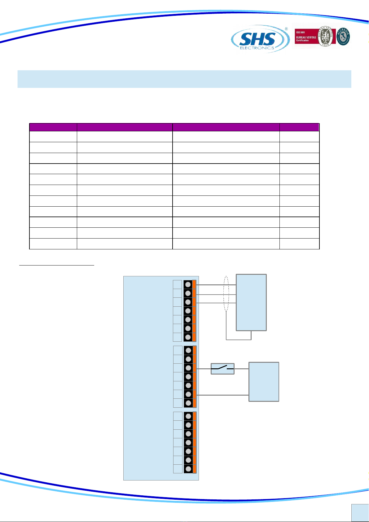
2.4 Encoder
Encoder connection to check the motor position.
CH A
TYPICAL APPLICATION
SIGNAL FUNCTION
IN1 CH A
IN2 CH B
CH B
ENC DER
-V
2.3 Enable Input
To switch on the power o the motor must be connect a signal to Enable Input (IN6).
Without this signal the drive stop the motor, there is not a deceleration ramp, and the motor phases current goes to
zero.
It’s possible have a drive where the IN6 is a Disable Input, see drive models table option.
It’s possible to remove enable/disable unction and have an other spare input, see drive models table option.
SIGNAL FUNCTION
IN6 Enable
+V
7
6
5
4
3
2
1
14
13
12
11
10
9
8
21
20
19
18
17
16
15
FB-
FB+
GND-FB
GND
AIN2
AIN1
VREF
AN UT
+VCC
IN6-EN
IN5-DIR
IN4-CLK
C MIN-B
IN3-CHZ
IN2-CHB
IN1-CHA
C MIN-A
UT3
UT2
UT1
C M UT
8
ENG
S.H.S. s.r.l. Via F.lli Rosselli, 29 20027 Rescaldina (MI) – ITALY Tel. +39 0331 466918 Fax. +39 0331 466147 www.shsitalia.it
3.1 Parameters setting
By using the buttons below the display (hereina ter re erred to as [] , [▼], [▲] ,[ѵ]) you can parameterize the
drive:
●To access to main menu, press [ѵ] per two seconds, it will visualize the irst available parameter.
●From main manu to select the desired parameter press the button [▼] or [▲].
●To visualize the actual value o parameter press [ѵ].
●From the parameter to change the value press [▼] or [▲].
●From the parameter to store the value press the button [ѵ] or two seconds and it will appear “memo” on the
display.
Some change require an automatic reset o the drive, or to a wait time to be e ective.
●From the parameter to come back at main menù without modi y any conditions, press [].
●From the main menu to go out press [].
●The password parameter use keyb [] to move the pointer beetwen the characters.
3.2 Display messages
3. SETTINGS
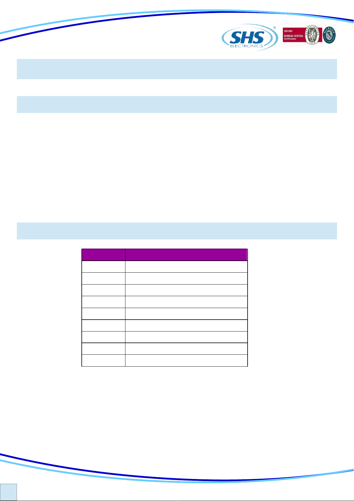
DISPLAY Description
rdy Drive K, motor stop
run Motor running
dis Drive disabled
temp ver temperature Error
uvoL Under Voltage Error
ovoL ver Voltage Error
oc ur ver Current Error
perr Generic Error
rSt Reset phase
In case o error, the drive will remove power to the motor.
To reset the over current and generic errors it’s necessary or switch o and on the drive.
To reset over temperature, under voltage or over voltage errors it’s necessary have the correct value.

9
ENG
S.H.S. s.r.l. Via F.lli Rosselli, 29 20027 Rescaldina (MI) – ITALY Tel. +39 0331 466918 Fax. +39 0331 466147 www.shsitalia.it
4. FUNCTION MODES
It is possible to set di erent unction modes by the “Mode” parameter.
Mode DESCRIPTION
“ PD” Step/direction command
“Modb” Modbus Fieldbus protocol
“ Win” Winstar Fieldbus protocol
“Can ” Can pen Fieldbus protocol
Basic Drive in Step Direction can’t have Mode option.
Winstar and Modbus drive can have Step/direction mode.
10
ENG
S.H.S. s.r.l. Via F.lli Rosselli, 29 20027 Rescaldina (MI) – ITALY Tel. +39 0331 466918 Fax. +39 0331 466147 www.shsitalia.it
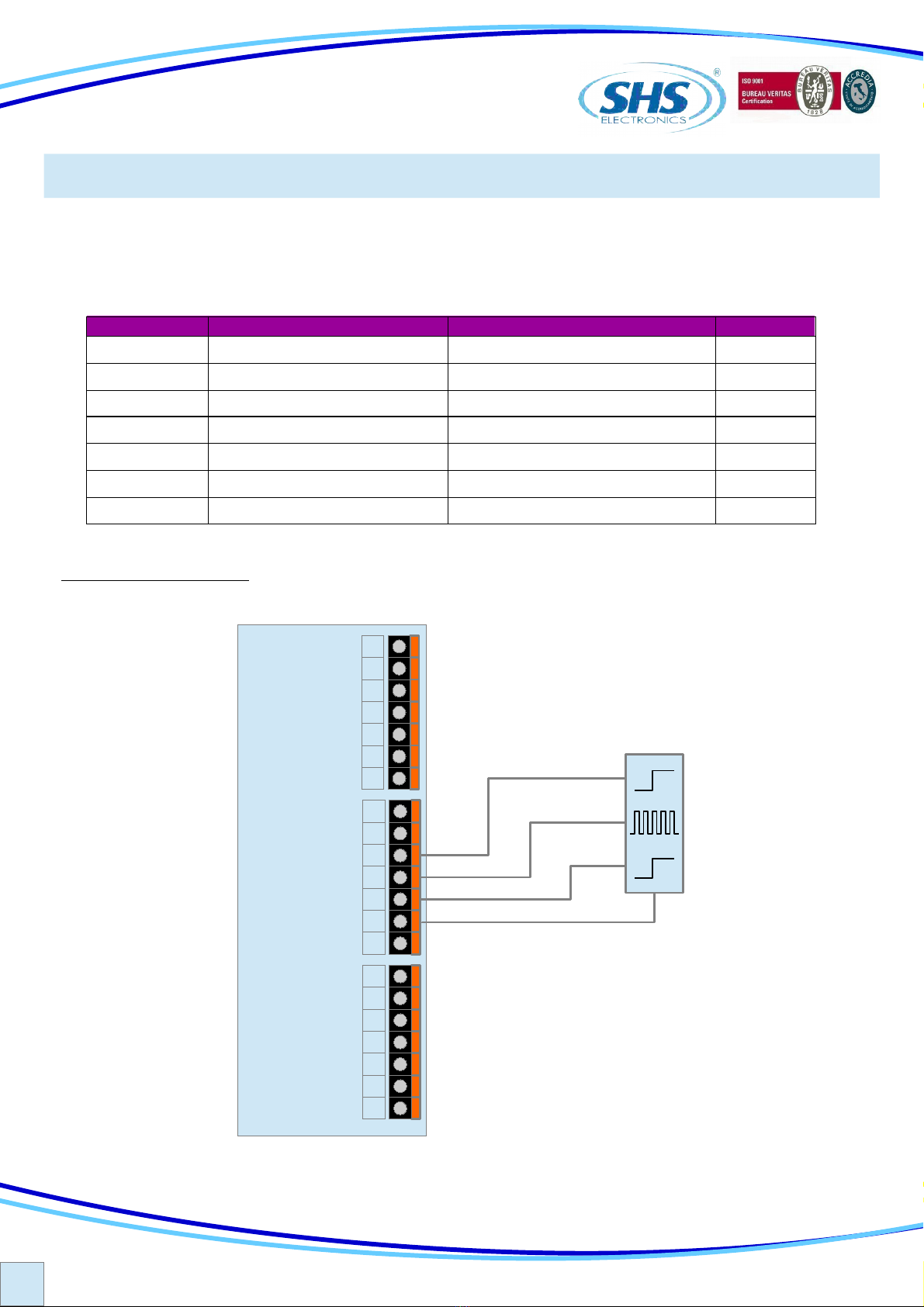
4.1 Step Direction Mode “ PD”
In Step/direction mode the drive execute a single step or each rising edge o the step-in signal
IN4 step in clock (Maximum requency 60KHz)
IN5 de ines the direction rotation.
IN6 enable the drive.
TYPICAL APPLICATION
PARAMETERS Function alues Reset
0par
Reset Eeprom values n Unaffected
c urr
Set the phase current [mA] See drive models table option 1000
res
Set the resolution [1/n steps] 1/1, 1/2, 1/4, 1/8, 1/16 1/2
redi
Set the reduction current value Zero Current, Imax/4, Imax/2, Imax Imax/4
redt
Set the reduction current time 10ms to 300ms 10
Firm
Firmware Release Variable Unaffected
pass
Password Alphanumeric value “----”
STEP
DIR
7
6
5
4
3
2
1
FB-
FB+
GND-FB
GND
AIN2
AIN1
VREF
AN UT
+VCC
IN6-EN
IN5-DIR
IN4-CLK
C MIN-B
IN3-CHZ
IN2-CHB
IN1-CHA
C MIN-A
UT3
UT2
UT1
C M UT
ENABLE
PLC
14
13
12
11
10
9
8
21
20
19
18
17
16
15
11
ENG
S.H.S. s.r.l. Via F.lli Rosselli, 29 20027 Rescaldina (MI) – ITALY Tel. +39 0331 466918 Fax. +39 0331 466147 www.shsitalia.it
The drive can support MODBUS-RTU protocol.
It is possible to set Address, Baud-rate and Parity.
Data ormat is N,8,1.
4.2 Modbus Mode “MODB”
TYPICAL APPLICATION
PLC
RS485
shield
7
6
5
4
3
2
1
14
13
12
11
10
9
8
21
20
19
18
17
16
15
FB-
FB+
GND-FB
GND
AIN2
AIN1
VREF
AN UT
+VCC
IN6-EN
IN5-DIR
IN4-CLK
C MIN-B
IN3-CHZ
IN2-CHB
IN1-CHA
C MIN-A
UT3
UT2
UT1
C M UT
0V
D+
D-
PARAMETERS Function alues Reset
0par
Reset Eeprom values n Unaffected
c urr
Set the phase current [mA] See drive models table option 1000
aud
BaudRate RS485[Kbps] 9.6, 19.2, 38.4, 57.6, 115.2 19.2
par
Parity RS485 “ no”, “even”, “ odd” “ no”
Addr
Node Modbus Address 0 to 31 1
Mode
Mode Function “ PD”, “Modb” “Modb”
res
Set the resolution [1/n steps] 1/1, 1/2, 1/4, 1/8, 1/16 1/2
redi
Set the reduction current value Zero Current, Imax/4, Imax/2, Imax Imax/4
redt
Set the reduction current time 10ms to 300ms 10
Firm
Firmware Release Variable Unaffected
pass
Password Alphanumeric value “----”
24 DC

12
ENG
S.H.S. s.r.l. Via F.lli Rosselli, 29 20027 Rescaldina (MI) – ITALY Tel. +39 0331 466918 Fax. +39 0331 466147 www.shsitalia.it
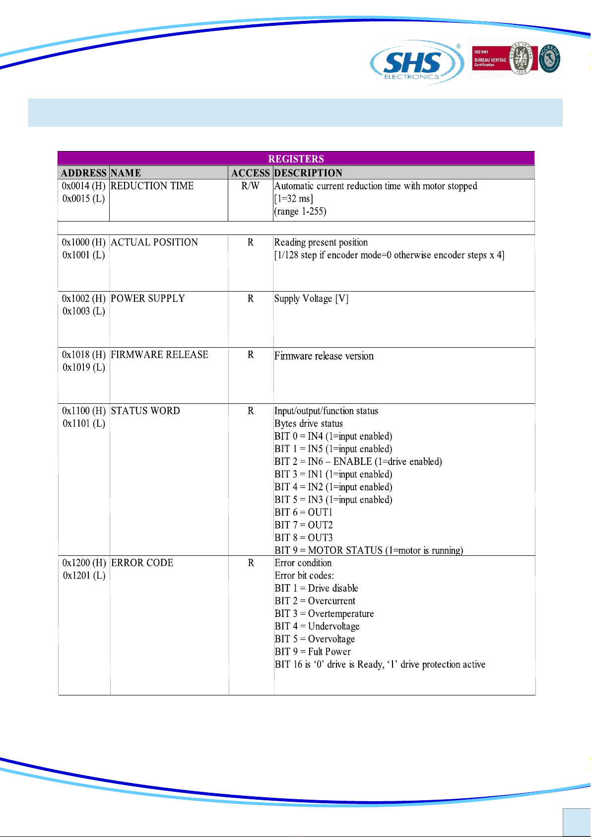
4.3 Register table
13
ENG
S.H.S. s.r.l. Via F.lli Rosselli, 29 20027 Rescaldina (MI) – ITALY Tel. +39 0331 466918 Fax. +39 0331 466147 www.shsitalia.it
Register table (cnt)

14
ENG
S.H.S. s.r.l. Via F.lli Rosselli, 29 20027 Rescaldina (MI) – ITALY Tel. +39 0331 466918 Fax. +39 0331 466147 www.shsitalia.it
The drive can support WINSTAR proprietary protocol.
It is possible to set Address, Baud-rate and Parity.
Data ormat is N,8,1.
4.4 Winstar Mode “ Uin”
TYPICAL APPLICATION
PLC
RS485
shield
7
6
5
4
3
2
1
14
13
12
11
10
9
8
21
20
19
18
17
16
15
FB-
FB+
GND-FB
GND
AIN2
AIN1
VREF
AN UT
+VCC
IN6-EN
IN5-DIR
IN4-CLK
C MIN-B
IN3-CHZ
IN2-CHB
IN1-CHA
C MIN-A
UT3
UT2
UT1
C M UT
0V
D+
D-
PARAMETERS Function alues Reset
0par
Reset Eeprom values n Unaffected
c urr
Set the phase current [mA] See drive models table option 1000
aud
BaudRate RS485[Kbps] 9.6, 19.2, 38.4, 57.6, 115.2 19.2
par
Parity RS485 “ no”, “even”, “ odd” “ no”
Addr
Node Modbus Address 0 to 31 1
Mode
Mode Function “ PD”, “ Uin” “ Uin”
res
Set the resolution [1/n steps] 1/1, 1/2, 1/4, 1/8, 1/16 1/2
redi
Set the reduction current value Zero Current, Imax/4, Imax/2, Imax Imax/4
redt
Set the reduction current time 10ms to 300ms 10
Firm
Firmware Release Variable Unaffected
pass
Password Alphanumeric value “----”
24 DC

15
ENG
S.H.S. s.r.l. Via F.lli Rosselli, 29 20027 Rescaldina (MI) – ITALY Tel. +39 0331 466918 Fax. +39 0331 466147 www.shsitalia.it
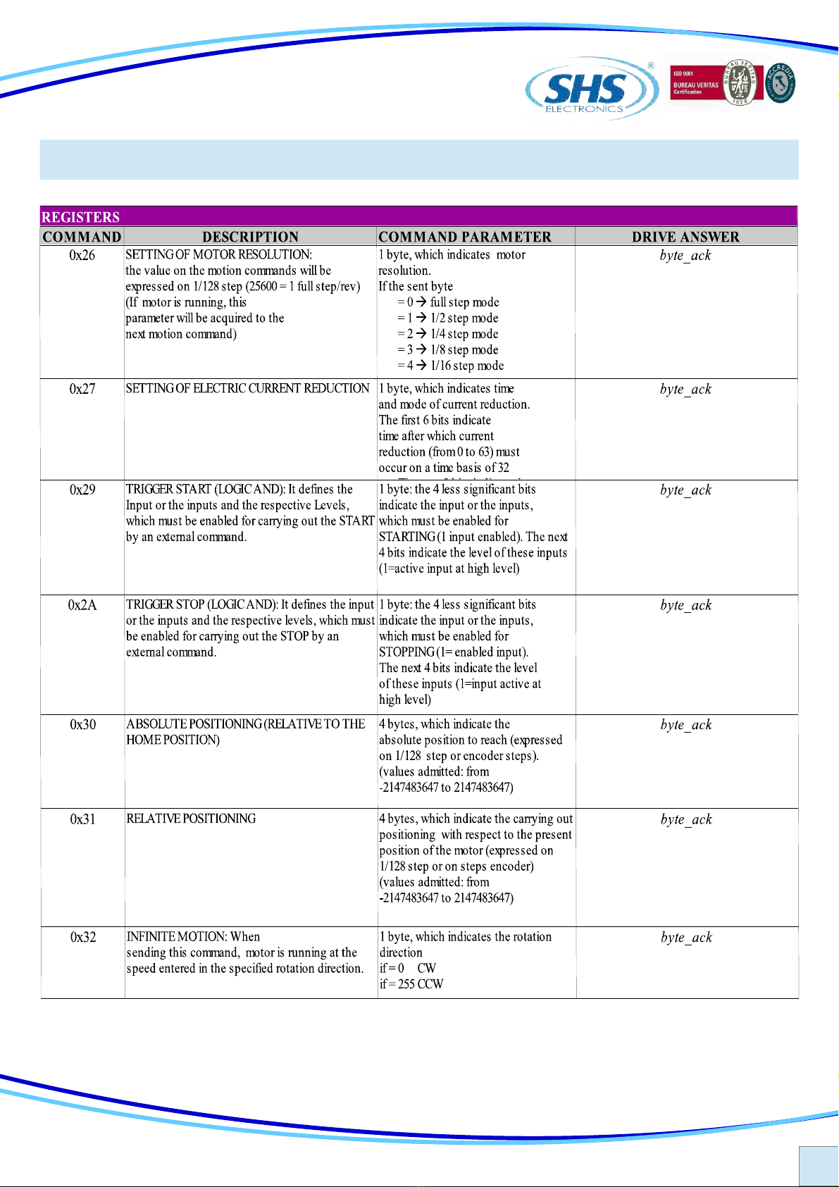
4.5 Command table
16
ENG
S.H.S. s.r.l. Via F.lli Rosselli, 29 20027 Rescaldina (MI) – ITALY Tel. +39 0331 466918 Fax. +39 0331 466147 www.shsitalia.it
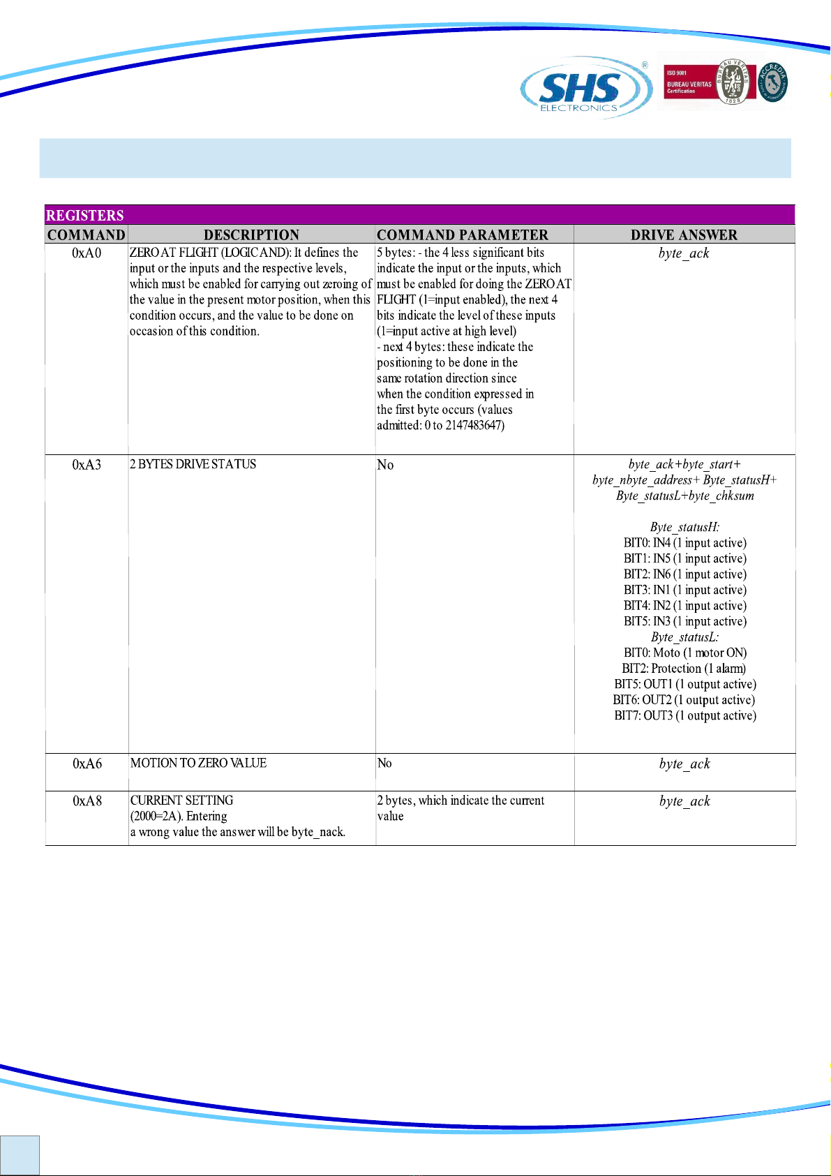
Command table (cnt)
17
ENG
S.H.S. s.r.l. Via F.lli Rosselli, 29 20027 Rescaldina (MI) – ITALY Tel. +39 0331 466918 Fax. +39 0331 466147 www.shsitalia.it
Command table (cnt)
18
ENG
S.H.S. s.r.l. Via F.lli Rosselli, 29 20027 Rescaldina (MI) – ITALY Tel. +39 0331 466918 Fax. +39 0331 466147 www.shsitalia.it

19
ENG
S.H.S. s.r.l. Via F.lli Rosselli, 29 20027 Rescaldina (MI) – ITALY Tel. +39 0331 466918 Fax. +39 0331 466147 www.shsitalia.it
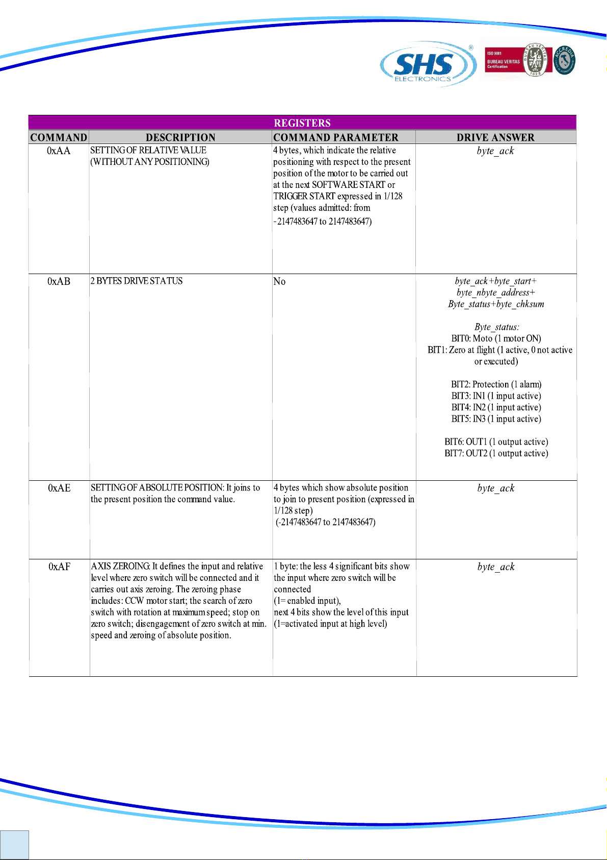
Command table (cnt)

20
ENG
S.H.S. s.r.l. Via F.lli Rosselli, 29 20027 Rescaldina (MI) – ITALY Tel. +39 0331 466918 Fax. +39 0331 466147 www.shsitalia.it
CODE yyyyOPTION
1 Encoder TTL
2 Input TTL
4 Display Bootm
8 EEprom special Firmware
16 Signal crimp connector
32 Power Screw connector
64 IN6 Disable input
128 IN6 spare input
The de aul con iguration it:
●Step Direction Command
●Input rom 12 to 24V
●Power and Signal Pluggable Connector
(*) not available or this drive
EXAMPLE 1: the de ault con iguration will become option 0 ( 00000 )
EXAMPLE 2: TTL Input + EEprom Firmware, will become option 2+8 = 10 ( 00010 )
HT3x1KK - yyyyy / Zzz
FIE DBUS:
WS = RS485 SHS Protocol
MB = Modbus
CO = CanOpen
OPTION:
View the ollowing table
SIZE:
2 = 4A 20..28Vdc
3 = 4A 20..60Vdc
5 = 8A 20..60Vdc
SPECIA VERSION:
Dzz = Dedicate So tware
Szz = Modi y Hardware (*)
5. HT3 MODELS CODE
Other manuals for HT3 Series
1
This manual suits for next models
2
Table of contents
Other SHS DC Drive manuals


