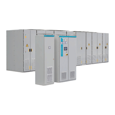
SINAMICS DCM •Base Drive panel instructions (1500A - 2800A DC)
2-2
2 Introduction (continued)
The AOP30 features a liquid crystal display (240 × 64 pixels) with backlighting for plain-text
display and a bar-type display for process variables. English, German, French, Spanish,
Italian and Chinese can be selected as the display languages.
The converter can also be parameterized on a standard PC with appropriate software
connected to the serial interface on the basic unit. This PC interface is used during start-up,
for maintenance during shutdown and for diagnosis in operation.
On 2-quadrant converters, a fully controlled three-phase bridge supplies the armature. On
4-quadrant converters, two fully controlled three-phase bridges are connected in an inverse-
parallel connection to allow both positive and negative armature current. For the field
converter, a single-phase, half-controlled 2-pulse bridge supplies the motor shunt field.
The armature and field converters can operate with AC line frequencies from 45–65 Hz. If
required for a specific application, the frequency of the armature and field AC supplies can be
different. The power section cooling system is monitored by means of temperature sensors.
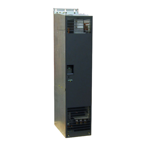
The power section for the armature and field converters is constructed of isolated thyristor
modules for converters rated from 1500A to 2800A at 575V, 690V, 830V and 950V, 3-phase
AC line voltages. The heat sink in this case is electrically isolated and at ground potential.
The housing and terminal covers on power connections provide protection against
accidental contact for operators working in the vicinity. All connecting terminals are
accessible from the top.
All open and closed-loop drive control and communication functions are performed by
powerful microprocessors. Drive control functions are implemented in the software as
program modules that can be “wired up” and changed by parameters.
2.3 Rated DC current
• The rating plate of the SINAMICS DCM Base drive panel has the rated Armature current
listed of the output rating for IEC DC I constant duty rating.
• The Base Drive Panels are designed using the DC I rating which means that fuses,
contactors and terminal blocks are sized for the full continuous DC I current.
• The DC I rating is the maximum current the power module can supply continuously with
no overload. Because an overload is not possible, the DC I rated current is higher than
the continuous DC II rating.
• The microprocessor calculates the current I2t value of the power section cyclically to
ensure that the thyristors are not damaged in overload operation.
• The DC II rated current allows operation by an overload of 150% for 60 seconds in a 40° C
ambient. The overload can be applied no sooner than every 15 minute intervals.
Overload capability
The rated DC current specified on the unit rating plate (maximum permissible continuous
DC current) may be exceeded in operation. The extent to which this value is exceeded and
how long this lasts are subject to certain limits. The absolute upper limit for the value of the
overload currents is 1.8x the rated DC current. The maximum overload duration depends on
the time characteristic of the overload current, as well as on the load history of the unit,
and also depends on the specific unit. Each overload must be preceded by an under load
(load phase with load current < rated DC current). Once the maximum permissible overload
duration has elapsed, the load current must return to at least an absolute value ≤ the rated
DC current. The SINAMICS DCM Base drive may be operated with five different overload
settings configured in the drive parameters.
