FOLSOM ScreenPRO FC-0608 Setup guide

INSTALLATION AND OPERATOR’S MANUAL
Model FC-0608
ScreenPRO Multi-Screen Remote
Manual #26-0111200-00 / Revision E

RECORD OF CHANGES
REV #
DATE
ECO #
DESCRIPTION
Approved By
A 05/31/2002 Release J. Spotts
B 07/31/2002 894 Added descriptions for new keyboard layout R. Pellicano
C 10/25/02 953 Clarifies descriptions of various items R. Pellicano
D 5/27/03 1063 Updated Menu Flow Chart. Updated Protocol
specification. Added Display Lock and Wide
Screen Raster descriptions. Clarified various
sections.
R. Pellicano
E 7/10/03 1099 Updated Menu Flow Chart. Updated Frame
Rate and Output Resolution selection
description.
R. Pellicano
Manual # 26-0111200-00

Operators Safety Summary
The general safety information in this summary is for operating personnel.
Do Not Remove Covers or Panels
There are no user-serviceable parts within the unit. Removal of the top
cover will expose dangerous voltages. To avoid personal injury, do not
remove the top cover. Do not operate the unit without the cover installed.
Power Source
This product is intended to operate from a power source that will not
apply more than 230 volts rms between the supply conductors or
between both supply conductor and ground. A protective ground
connection by way of grounding conductor in the power cord is essential
for safe operation.
Grounding the Product
This product is grounded through the grounding conductor of the power
cord. To avoid electrical shock, plug the power cord into a properly wired
receptacle before connecting to the product input or output terminals.
A protective-ground connection by way of the grounding conductor in the
power cord is essential for safe operation.
Use the Proper Power Cord
Use only the power cord and connector specified for your product. Use
only a power cord that is in good condition. Refer cord and connector
changes to qualified service personnel.
Use the Proper Fuse
To avoid fire hazard, use only the fuse having identical type, voltage
rating, and current rating characteristics. Refer fuse replacement to
qualified service personnel.
Do Not Operate in Explosive Atmospheres
To avoid explosion, do not operate this product in an explosive
atmosphere.
Terms In This Manual
Highlights an operating procedure, practice,
condition, statement, etc., which, if not strictly
observed, could result in injury to or death of
personnel.
NOTE Highlights an essential operating procedure,
condition or statement.
CAUTION
The exclamation point within an equilateral triangle is
intended to alert the user to the presence of important
operating and maintenance (servicing) instructions in the
literature accompanying the appliance.
AVERTISSEMENT!
Le point d´exclamation dans un triangle equilatéral signale
à alerter l´utilisateur qu´il y a des instructions d´operation
et d´entretien tres importantes dans la litérature qui
accompagne l´appareil
WARNING
VORSICHT ein Ausrufungszeichen innerhalb eines gleichwinkeligen
Dreiecks dient dazu,
den Benutzer auf wichtige Bedienungs-und
Wartungsanweisungen in der Dem
Great beiliegenden Literatur aufmerksam zu machen.
The rear panel ON/OFF switch does not
disconnect the unit from input AC power. To facilitate disconnection of
AC power, the power cord must be connected to an accessible outlet
near the unit. Building Branch Circuit Protection: For 115 V use 2 A, for
230 V use 1 A.
When the Controller is used in the 230-volt mode, a UL listed
line cord rated for 250 volts at 15 amps must be used and
must conform to IEC-227 and IEC-245 standards. This cord
will be fitted with a tandem prong-type plug.
WARNING
WARNING
Terms As Marked on Equipment
Highlights an operating procedure, practice, condition, statement, etc., which, if not strictly observed, could result in injury to or
death of personnel.
CAUTION
The exclamation point within an equilateral triangle is intended to alert the user to the presence of important operating and
maintenance (servicing) instructions in the literatureaccompanying the appliance.
AVERTISSEMENT!
Le point d´exclamation dans un triangle equilatéral signale à alerter l´utilisateur qu´il y a des instructions d´operation et d´entretien
tres importantes dans la litérature qui accompagne l´appareil
VORSICHT
Ein Ausrufungszeichen innerhalb eines gleichwinkeligen Dreiecks dient dazu, den Benutzer auf wichtige Bedienungs-und
Wartungsanweisungen in der Dem Great beiliegenden Literatur aufmerksam zu machen.
NOTE This equipment has been tested and found to comply with the limits for a Class A digital device, pursuant to Part 15 of the FCC Rules.
These limits are designed to provide reasonable protection against harmful interference when the equipment is operated in a commercial
environment. This equipment generates, uses, and can radiate radio frequency energy and, if not installed and used in accordance with the
instruction manual, may cause harmful interference to radio communications. Operation of this equipment in a residential area is likely to cause
harmful interference, in which case the user will be required to correct the interference at the users own expense.
CAUTION

Table of Contents
Chapter 1 – Introduction___________________________________________________________ 1
About the ScreenPRO Remote________________________________________________ 2
Features__________________________________________________________________ 2
Technical Description________________________________________________________ 3
Chapter 2 – Installation____________________________________________________________ 5
Power Cord/Line Voltage Selection____________________________________________ 6
Video Input & Output Connections_____________________________________________ 7
ScreenPro and Controller Connections_________________________________________ 7
Chapter 3 – Operation_____________________________________________________________ 9
Controller Menu Flow Chart___________________________________________________ 10
Configuration of ScreenPro Units_______________________________________________ 11
Console Feature Overview____________________________________________________ 12
Screen Destinations_________________________________________________________ 12
Presets___________________________________________________________________ 12
Next Preset Key____________________________________________________________ 13
PIP Presets_______________________________________________________________ 13
Configuration Keypad________________________________________________________ 15
Input Selection_____________________________________________________________ 16
Group Functions____________________________________________________________ 16
Learning Groups___________________________________________________________ 16
Input Configuration__________________________________________________________ 17
Output Configuration________________________________________________________ 22
System Configuration________________________________________________________ 26
File Configuration Menu______________________________________________________ 31
Patterns Keypad____________________________________________________________ 31
Transition Rates____________________________________________________________ 32
Destination, Program & Preview Selections_______________________________________ 33
Transition Selection_________________________________________________________ 33
Luminance Keying Operation__________________________________________________ 34
Picture-In-Picture Operation___________________________________________________ 35
PIP Link Operation__________________________________________________________ 36
Freeze Function Operation___________________________________________________ 37
Black Program and Black Preview______________________________________________ 37
File Mapping Tutorial________________________________________________________ 38
Chapter 4 – Sofware Upgrade Instructions__________________________________________ 41
Special Programming Instructions______________________________________________ 43
Chapter 5 – External Remote Control Protocol________________________________________ 47
Serial Parameters__________________________________________________________ 48
Console Port (DB-9) Pin-out__________________________________________________ 48
Protocol Specification_______________________________________________________ 48
Destination Selection________________________________________________________ 50
Group Selection____________________________________________________________ 52
Keyboard Map_____________________________________________________________ 54
Serial Remote Commands___________________________________________________ 55
Chapter 6 – Folsom Research Information____________________________________________ 61
Folsom Research Warranty___________________________________________________ 62
RMA Information___________________________________________________________ 62
Technical Support/General Contact Information___________________________________ 62

Manual #26-0111200-00 / Revision E ScreenPro Multi-Screen Remote 1
1
CHAPTER ONE
Introduction
What you will find in this chapter…
About the ScreenPro Remote Controller
Features
Technical Description
Model FC-0608
ScreenPRO Multi-Screen Remote Controller

Manual #26-0111200-00 / Revision E ScreenPro Multi-Screen Remote 2
Introduction
About the ScreenPRO Remote
The controller provides a professional production switcher user interface to the Folsom ScreenPro seamless graphics
switchers. Equipped with easy to use menus, t-bar transition control and joystick for intuitive adjustments. Your
ScreenPro will be easier to set-up and use than ever before. Specifically designed for live applications, the features
you need are right at your fingertips.
Attention to the Installation and Operation Sections of this manual is important to ensure trouble-free operation.
Should you have any questions regarding the operation of this unit, please consult the factory.
Features
The ScreenPRO Remote provides and offers the following features when interfaced with up to six ScreenPRO
graphics switchers:
•Modular design supports up to six screens.
•Integrated user interface.
•Up to 8 universal inputs; accepts composite (NTSC and PAL), s-video, component, and computer sources.
•Requires no external decoders or line doublers.
•Automatically syncs to input videos with resolutions from 640x480 to 1600x1200.
•High-performance architecture supports seamless switching.
•(2) Program and (1) Preview output for each screen.
•Superior image quality.
•17 transition effects including cuts, fades, dissolves, curtains, grids, and wipes with variable transition rates.
•Effect selection for single or multi-screen effects.
•32 Presets
•Screen “grouping” allows simultaneous transitions on selected screens.
•File management between multiple ScreenPro seamless switchers
•T-bar for manual control of transitions.
•Joystick simplifies setup of inputs and outputs.
•Six test patterns for projector setup.
•Motion adaptive de-interlacing.
•User programmable output formats: VGA (640x480), SVGA (800x600), XGA (1024x768), 1024x768 II,
SXGA (1280x1024), SXGA II (1280x1024), (1280x720), (1280x768), (1280x960), (1365x768), (1365x1024).
•Fully field programmable to support upgrades.
•PIP capability including enlarging a pip to fill multiple output screens.
•Luma Keying functionality.

Manual #26-0111200-00 / Revision E ScreenPro Multi-Screen Remote 3
Technical Description
The Controller simplifies system interconnections, setup, and control while supporting advanced features for
presentations with up to six screens. The multi-screen presentation system includes an intuitive user interface that
automatically configures itself to the number of ScreenPRO units in the presentation.
The operator can select from up to 8 universal inputs that accept composite video, s-video, component video, and
computer video sources (640x480 VGA to 1600x1200 UXGA). Sources are scaled to match the native resolution or
"sweet spot" of the projection devices to ensure optimal image quality. Seventeen different transition effects including
dissolves, wipes, cuts, and fade are supported. The duration of each transition effect is programmable. Each screen
output supports two buffered program outputs (one five-wire BNC and one HD-15) and a preview output (HD-15).
While other systems require multiple control units for a multi-screen show, all Controller functions (including system
setup) are supported via a single user interface. The user interface simplifies system setup, adjustment, and control.
To perform a transition, the operator simply selects a preview source(s) and presses a key to simultaneously
transition from one to six screens using any of the seventeen transition effects. Thirty-two preset memories allow
complex control sequences to be “learned” for quick recall. Presets can include information about sources, effects,
transition rates, PIP, and Keying. Since all presets are recalled to the preview monitors, the operator can view, edit,
and recall presets without affecting the program outputs.
The Controller has been designed to work seamlessly with Folsom's ScreenPro product offerings. This allows
customers to utilize Folsom's ScreenPro products for both single-screen and multi-screen applications.
A functional connectivity diagram of the unit is provided below.
FC-0608
Console Video Cables
25 Pin Serial Cable
FC-0608 Wiring
Video
Inputs
ScreenPRO
Video
Inputs
ScreenPRO
Video
Inputs
ScreenPRO
Video
Inputs
ScreenPRO
CBB-6X
Video
Inputs
ScreenPRO
Video
Inputs
ScreenPRO


Manual #26-0111200-00 / Revision E ScreenPro Multi-Screen Remote 5
2
CHAPTER TWO
Installation
What you will find in this chapter…
Power Cord/Line Voltage Selection
Video Input & Output Connections
Connecting ScreenPro Units
Model FC-0608
ScreenPRO Multi-Screen Remote Controller
Manual #26-0111200-00 / Revision E ScreenPro Multi-Screen Remote 6
Installation
Power Cord/Line Voltage Selection
The ScreenPro Remote performs line Voltage Selection Automatically. No user controls are required for line voltage
selection.
When the Controller is used with 230-volt supplies, a UL listed line cord rated for 250
volts at 15 amps must be used. This cord will be fitted with a tandem prong-type plug.
Figure 5-2: Tandem Plug
La choix de la ligne de voltage se realize automatiquement par I’Controller Transformateur
Graphique On n’apas besoin du controller usager pour la choix de la ligne de voltage.
Das Controller-Gerät mu beim Anschlu an 240V ~ mit einer vom VDE auf
250V/10A geprüften Netzleitung mit einem Schukostecker ausgestattet sein.
WARNING
AVERTISSEMENT
AVERTISSEMENT

Manual #26-0111200-00 / Revision E ScreenPro Multi-Screen Remote 7
Video Input Connections
The video input section on the ScreenPro rear panel provides 8 universal inputs. Each input can accept RGB, YUV,
S-Video (Y/C), or composite (NTSC or PAL) video signals. The connections for each input channel are made via five
BNC connectors. Connection points for each type of video signal are specified below.
Input Connections
Format – RGB
(Typical Devices: Computers)
Format – YUV or Y Pr Pb (Betacam)
(Typical Devices: DVD Player or Betacam Deck)
Source to ScreenPro Source to ScreenPro
R R/CR Y G/Y
G G/Y Pr R/CR
B B/CB Pb B/CB
H H/C or
V V Y G/Y
U R/CR
Format – S-Video (Y/C)
(Typical Devices: S-Video VCR) V B/CB
Source to ScreenPro Format – NTSC/PAL (Typical Devices: Composite/PAL VCR)
Y G/Y Source to ScreenPro
C B/CB Composite/PAL G/Y
Video Output Connections – Program Outputs
Two independently buffered Program outputs (one five wire BNC connection and one HD-15) are provided for each
output screen. Either of these outputs may be used to connect to the display device used for the presentation. The
second output is designed to support a local display in the event that the operator is unable to conveniently view the
presentation.
Both outputs provide RGB video signals. Connect the outputs labeled R,G, and B on the rear panel of the ScreenPro
unit to the correspondingly labeled connectors on the output device.
The operator can select the type of output sync to match application requirements. Separate C (Composite) or
separate H/V (Horizontal/Vertical) sync modes are supported. Connect the C or H sync signals from ScreenPro to the
correspondingly labeled connectors on the output device. If separate H/V sync mode is being used, be sure to
connect the V signal from the ScreenPro to the correspondingly labeled connector on the output device.
Preview Output
One Preview output (on an HD-15 connector) is provided for each output screen. The Preview outputs are provided
to permit the operator to view the next source video to be displayed prior to initiating a transition. The Preview outputs
provide RGB video signals. Connect the outputs on the rear panel of the ScreenPro unit to the correspondingly
labeled connectors on the output device.
The operator can select the type of output sync to match application requirements. Separate C (Composite) or
separate H/V (Horizontal/Vertical) sync modes are supported. Connect the C or H sync signals from ScreenPro to the
correspondingly labeled connectors on the output device. If separate H/V sync mode is being used, be sure to
connect the V signal from the ScreenPro to the correspondingly labeled connector on the output device.
ScreenPro and Controller Connections
For single screen applications, connect the Remote Port (DB-25 connector on the rear of the Controller) to the
ScreenPRO’s REMOTE Connector located on the rear panel using the 25 ft. 25-pin straight-thru serial provided with
the controller.
For multi-screen applications, connect the Remote Port (DB-25 connector on the rear of the Controller) to the
Communication Breakout Box (CBB-6X supplied with the Controller) using the 25 ft. 25-pin straight-thru serial cable
provided with the controller. Connect each ScreenPRO’s REMOTE port to the Breakout Box using a DB-25 male to
DB-25 male 25-pin straight-thru serial interface cable. Any ScreenPRO can be connected to any available port on
the Breakout Box.
Additional interface cables are available from Folsom Research. Order FRI (P/N 14-9760031-00).


Manual #26-0111200-00 / Revision E ScreenPro Multi-Screen Remote 9
3
CHAPTER THREE
Operation
What you will find in this chapter…
ScreenPRO Menu Flow
Configuration of External ScreenPro Units
Console Overview
Screen Destinations
Presets
Configuration Keypad: Input, Output, and System Menus
Patterns Keypad: Wipe Effects and Transition Rates
Destination, Program, and Preview Selections
Picture In Picture Operation
Luminance Keying Operation
Freeze Function Operation
Black Program and Black Preview
PIP Link Operation
Model FC-0608
ScreenPRO Multi-Screen Remote Controller

Manual #26-0111200-00 / Revision E ScreenPro Multi-Screen Remote 10
Operation
This portion of the manual provides instructions that indicate how to control all ScreenPro functions. Keys on the FC-
0608 console are used to select sources and control transitions to support real-time control of presentations. The
graphical display and menus are designed to simplify setup and adjustment of the entire video presentation system.
IN:8 SCN:6 BP:0
EFF: MIX PG:1
RATE:1.0 M_RATE:1.0
Status Menu
INPUT CFG S#-IN_##
PREVIEW SCREEN #
ADVANCED ->
RAS TOPLFT JOY XY
RAS BTMRGT JOY XY
BRIGHTNESS ###.#
CONTRAST ###.#
INPUT TYPE RGB
INPUT SYNC SOG
COLOR BALANCE ->
PROCESSING ->
RESET INPUT [+]
DEL CONFIG [+]
CANCEL CONFIG [+]
SAVE CONFIG [+]
SAVE AS ->
IN P U T M e n u
<-ADVANCED S#-IN_##
AUTOCONFIG [+]
PHASE_ADJ ->
H TOTAL ####
POS (R) ###
WIDTH (L) ####
TOP EDGE JOY Y
BOTTOM EDGE JOY Y
<-PHASE ADJUST
SCREEN #
PROGRAM ##
PREVIEW ##
Advanced Menu
Phase Adjust M enu
<-RGB COLBAL S#-IN_##
R CONT ###.#
R BRIGHT ###.#
G CONT ###.#
G BRIGHT ###.#
B CONT ###.#
B BRIGHT ###.#
RESET BAL [+]
RGB
<-YUV COLBAL S#-IN_##
SATURATION ###
R CONTRAST ###.#
R BRIGHTNESS ###.#
G CONTRAST ###.#
G BRIGHTNESS ###.#
B CONTRAST ###.#
B BRIGHTNESS ###.#
RESET BALANCE [+]
YUV
<-ENC COLBAL S#-IN_##
CHROMA LEV ###
CHROMA PHS ###
RESET BAL [+]
COM P/SVID
Color Balance
Menus
<-PROCESSING S#-IN_##
ASPECT RATIO FULL
DC-REST OFF
DI BYPASS OFF
32PD DETECT OFF
Processing M enu
OUTPUT CFG
SCREEN #
FORMAT ####x####
FRAME RATE ##.##
OUTPUT SYNC +H+V
MONITOR SYNC +H+V
TEST PATTERN ->
DISPLAY LOCK OFF
*WIDE-SCN RASTER OFF
OUTPUT Menu
<-TEST PATTERN
TEST PAT MODE OFF
PATTERN N/A
OVERLAY MODE PREVIEW
AR BOX ON
GRID N/A
Test Pattern M enu
SYSTEM CFG
DEFINE WINDOWS ->
TRANSITION EDGE ###
VFD BRIGHTNESS ##
SOFTWARE VERSIONS ->
TECH SUPPORT ->
RECALL OPTIONS ->
DIAGNOSTICS ->
CONFIG SERIAL ->
RESET SPRO [+]
RESET ALL [+]
DEFINE BLK KEYS BLK
SYSTEM Menu <- RECALL OPTIONS
PREVIEW ON
EFFECT ON
RATE ON
Recall Options
Diagnostics M enu
Folsom Research,Inc.
ScreenPro Rem ote Menu Flow
<- DEFINE WINDOWS
SCREEN #
OUTPUT PREVIEW
MODE OFF
H SIZE ###
V SIZE ###
H CENTER ###
V CENTER ###
RESET [+]
Define W indow s
<- DIAGNOSTICS
VFD TEST ->
JOYSTICK / TBAR TEST ->
KEY DETECTION TEST ->
LED TEST ->
SCN DETECTION TEST ->
<- VFD TESTS
BRIGHTNESS TEST [+]
PIXEL TEST [+]
<- JOYSTICK / TBAR TEST
X = XXX%
Y = XXX% TBAR = XXX.X%
Z = XXX%
<- KEY DETECTION TEST
KEY INFO:
COL=X ROW=X PRESSED
KEY DESCRIPTION
<- LEDS TEST
[+] TO START TEST
Softw are Versions
<- SYSTEM SW VER 5.00
SP / SPP SW VERSION ->
*BLENDPRO SW VERSION ->
SAVE AS
FILE NUMBER ##
FILE NAME
SAVE [+]
Save As Menu
ICFG FILE MAPPING
SCREEN #
IN 1 # NAME
IN 2 # NAME
IN 3 # NAME
IN 4 # NAME
IN 5 # NAME
IN 6 # NAME
IN 7 # NAME
IN 8 # NAME
FILE M enu
<- SP / SPP SOFTWARE VERSION
B1:5.00 B4:5.00
B2:5.00 B5:5.00
B3:5.00 B6:5.00
<- BLENDPRO SOFTWARE VERSION
BP1:1.00
BP2:1.00
Software Version M enus
Diagnostic Menus
<- TECH SUPPORT
SOFT VER: 5.00
PHONE: 866.FRI.SUPT
866.374.7878
Tech Support
<- CONSOLE PORT MENU
BAUD RATE 57600
DATA BIT 8
STOP BIT 1
PARITY NONE
ECHO ON
RESET CONFIG [+]
Config Serial M enu
* These item s w ill o n ly s h o w
if BlendPros are attached
<- SCN DETECTION TEST
[+] TO START TEST
Manual #26-0111200-00 / Revision E ScreenPro Multi-Screen Remote 11
Configuration of ScreenPro Units
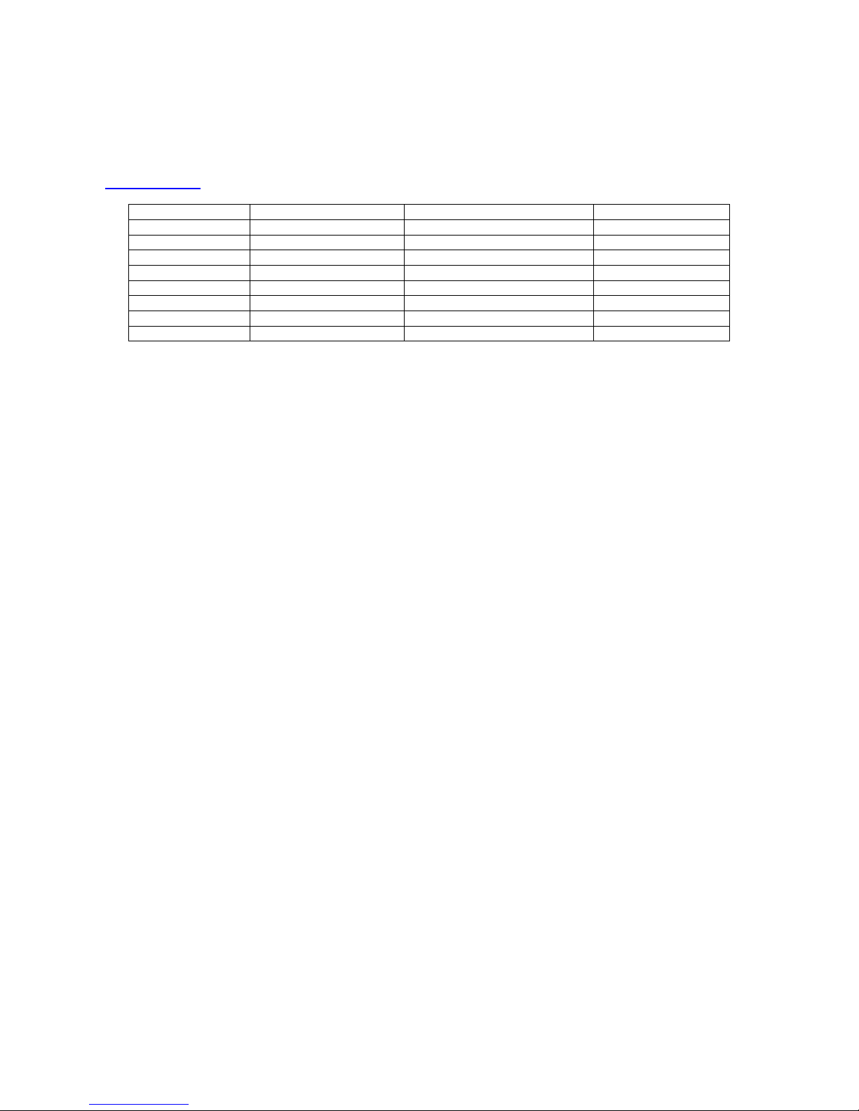
NOTE: Use the chart below to help determine which software is compatible between systems. Other combinations of
software are NOT guaranteed to operate properly. If you are unsure about the software versions you have, consult
the factory for assistance. This table is subject to change without notice. Please check the web site
(www.folsom.com) for current information.
Release Number ScreenPro Software FC-0608 Controller Software BlendPro Software
1 25.00.P – 25.00.T Versions Prior to 2.10 N/A
2 31.00.A 2.10 N/A
3 31.00.A 2.20 N/A
4 31.00.A 2.22 N/A
5 35.00.C 2.55 1.03 or higher
6 35.00.D 2.55 1.03 or higher
7 5.02 5.02 1.03 or higher
8 5.03 5.03 1.03 or higher
Software Compatibility Chart
ScreenPro units must be powered up and configured for remote control before the controller is turned on. To
configure the ScreenPro units, connect them as shown in the wiring diagram in the Technical Description section of
this document and then turn the units on. After a 50 second initialization period, the ScreenPro units will display the
Main menu.
To enter remote control mode, press the MISC key on the ScreenPro front panel. Use the ADJUST control knob to
scroll down to the item labeled EXT REMOTE CTRL. Press the SELECT key to select the external control feature.
The ADJUST control can now be used to select among the supported modes of operation. Use the ADJUST knob to
select the proper mode (SPR EXT ID #1 for Screen 1, SPR EXT ID #2 for Screen 2, SPR EXT ID #3 for Screen 3,
SPR EXT ID #4 for Screen 4, SPR EXT ID #5 for Screen 5, or SPR EXT ID #6 for Screen 6). Note that each
ScreenPRO must be configured with a unique ID number, the first ScreenPRO must have ID #1, and screens must
be assigned sequentially from left to right. After the proper mode is selected press the SELECT key to activate the
selected mode. The display will indicate the selected remote control settings and the backlighting of the lamps on the
front panel will be turned off to remind the user that remote control mode has been selected.
To exit remote control mode and re-enable the ScreenPRO front panel, select STANDALONE mode in the EXT
REMOTE CTRL menu and press the SELECT key. The ScreenPro unit will return to stand alone mode and the keys
will again be backlit.

Manual #26-0111200-00 / Revision E ScreenPro Multi-Screen Remote 12
Console Feature Overview
12345678
Screen
1
Screen
2
Screen
3
Screen
4
Screen
5
Screen
6All Clear
1
9
17
25
2
10
18
26
3
11
19
27
4
12
20
28
5
13
21
29
6
14
22
30
7
15
23
31
8
16
24
32
Black
Preview
Clear
Freeze
Freeze
Preview
Freeze
Program
Black
Program
Clear
Key
Key
1
Key
2
PIP
Link
Clear
PIP
PIP
1
PIP
2
Preset
Page
Wipe Mix CUT AUTO
TRANS
Key
3
Key
4
Key
5
Key
6
PIP
3
PIP
4
PIP
5
PIP
6
Learn
12345678
REV USER
RATE - / OFF + / ON CANCEL
PIP
ASAVE
INPUT OUTPUT SYSTEM FILE
MULTI MULTI
PIP
B
PIP
C
PIP
D
Preview
Program
Destination
Presets
PIP Functions
Key Functions
Group Functions Transition
Functions
Next
Preset
Group
1
Group
2
Group
3
Group
4
Screen Destinations
The FC-0608 can support up to six Screen Destinations. Sources selected to drive Screen Destinations will be scaled
to the selected output resolution. Screen Destinations support smooth transition effects at variable Rates using “Cut”
and “Auto Trans” or the T-Bar. Input, Transition Rate and Pattern information can also be stored as a Preset for quick
recall.
Presets
Presets are memory locations internal to the controller that can be programmed with system configuration information
for instant recall. Destination, Input, Pattern, Effect, and Transition Rates can be stored in a preset. The FC-0608 has
4 pages of 8 Presets, for a total of 32. The Preset Page key is used to select one of four possible pages as identified
on the VFD display.
Once a Preset has been recorded, all of the information will be recalled to Preview with a single button push. It can
then be transitioned to Program with “Cut,” “Auto Trans,” or “T-Bar.” All Presets are learned from and recalled to
Preview.
The Preset memories can include:
•Input Selection(s)
•Transition Rate
•Individual Screens
•Keying parameters
•Types of transition Effects/Mix
•PIP parameters
•PIP LINK parameters
When a preset has been programmed, its key will illuminate when recalled. If a preset has not been programmed,
the corresponding preset key will not illuminate when pressed.
In the SYSTEM menu, selecting RESET ALL will clear all stored presets.
Preset Tutorial
Presets can convert what would have been a time-consuming transition setup to be a single-button recall to Preview.
The Preset we will build is a pretty common type of scenario (graphics on the outside screens and I-Mag on center
screen) This Preset will reduce approx. 10 button keystrokes to a single-button recall to Preview.

Manual #26-0111200-00 / Revision E ScreenPro Multi-Screen Remote 13
We need to make a few assumptions before beginning:
Screens 1 & 3 are our GFX Screens
Screen 2 is assigned our I-Mag Screen
The Preset we will build will have the following information:
Screens 1 & 3 will have Input 8
Screen 2 will have Input 1 (cam 1)
(All Screens will use a 1.0 sec rate with a wipe-down effect)
Learning a Preset
On the Destination Bus push the Clear key and then select Screens 1 and 3. On the Preview bus, select Input 8
(PVW on Screen 1 & 3 switches will change to 8). Then select the Wipe-Down Effect on the Effect keypad and set the
Rate to 1.0 sec.
Now, push the Clear key again and then select Screen 3 on the Destination Bus (Screens 1 & 3 will be dark). On the
Preview bus select Input 1 (our Cam 1). At this point, all the information that we wanted is in a Preview state.
On the Destination Bus select Screens 1 and 3. At this point Screens 1, 2 and 3 will be the active destinations on the
preview bus, which is what we want learned to the Preset.
Note: Any information on Destinations (on the preview bus) NOT selected (unlit), will not be saved to a Preset when
learned.
Press and release Preset Page key until the PG: field on the controller display shows 1.
Press and hold the Learn key, and press Preset 1. The information is now learned to Preset 1 and can be recalled to
Preview at any time.
Changing Preset Information
Once a Preset is recalled (always to PVW), suppose you want to switch Screen 2 (the I-Mag screen & record deck)
from Input 1 (cam 1) to Input 2 (cam 2).
To do this:
Press and hold Screen 2 on the Destination Bus, and select input 2 on the Preview bus.
The new input is now in Preview and you can make the transition. If you want to save this change to Preset
1, press and hold Preset Learn and select Preset 1. The change is now saved.
If this is a one-time change and you want keep Preset 1 as it was originally learned, simply do not re-learn it.
When Preset 1 is recalled again, it will still have Input 1 (cam 1) learned to it.
Viewing a Preset
Press the Preset Page key until the PG: field on the controller display shows the desired page number. Press a
Preset memory key. The information learned to that memory location, if programmed, will go to Preview, and the
appropriate Destination and Preview Input source buttons will light. If the selected preset key does not light, no
information was stored in that preset and there is no information available to recall.
Next Preset Key
The NEXT PRESET key will allow the user to cycle through all available presets without having to press a preset
button. For example, if Presets 1,2 and 4 have saved information and Preset 4 is currently recalled, pressing Next
Preset will recall Preset 1 into Preview. Pressing the Next Preset key again will recall Preset 2 and so forth. The user
still has to initiate a transition for this look to go to program.
It is possible that Multiple Input sources will be lit on the Preview bus because each destination is capable of having a
different input source. You can press and hold an individual Destination switch on the Destination Bus and the
Preview and Program bus will go dark except for the inputs associated with the selected Destination.
PIP Presets
To save PIP size and position parameters for quick recall, size and position an image in Screen 1 Preview. (PIP
presets are only learned from Screen 1 Preview.) Hold the Learn key down and then press the PIP A, PIP B, PIP C or

Manual #26-0111200-00 / Revision E ScreenPro Multi-Screen Remote 14
PIP D key. The size and position of the PIP will be saved in non-volatile memory in the controller. To recall this
preset, press the appropriate PIP [A-D] key. All active preview screens will have the PIP recalled to them.
Keying Presets
To save KEYING parameters for quick recall, use the Learn Key. For example, configure the image you want to key
in Preview on a specific screen. Press and hold the Learn Key and press Preset 1. The keying parameters are now
saved in Preset 1. To verify that the keying parameters are saved, simply press the Preset 1 key.
Configuration
Configuration is done using the Configuration Keypad and the joystick. Changes and settings are viewed on the VFD
Display. Configuration includes Input Configuration, Output Configuration, and System Configuration.
The easy to use Configuration menus are keypad driven. Abbreviated instructions are viewed on the VFD Display to
assist in menu navigation.
The following abbreviations are frequently used:
o[JOY XY] - this adjustment is done by moving the joystick up and down or left and right
o[JOY Y] - this adjustment is done by moving the joystick up and down
o[+] - this function is activated by pressing the +/ON key
oÆ- use the right arrow key to display the next menu
Menu navigation is performed using the arrow keys.
oThe right arrow key, indicated by Æ, is used to display the next menu.
oThe left arrow key, indicated by Å, is used to exit a menu and return to the previous menu.
oThe up and down arrow keys are used to move within a menu. The current menu item will be highlighted to
indicate that it is the current choice.
oMost of the menu selections are updated by pressing the +/ON key to increment the item or the -/OFF key to
decrement the item. The joystick knob can be used in most cases as well to change a value.
oTo Exit a menu, press and hold the Åkey and push any “Menu” key (INPUT, OUTPUT, SYSTEM or FILE).
After leaving a menu, only the Status information will be shown on the VFD.
Status Configuration Display
The first three lines of the VFD display are dedicated to the display of the system status information. This information
includes:
oNumber of available input sources (IN: #)
oNumber of ScreenPROs detected in the configuration (SCN: #)
oNumber of BlendPros detected in the configuration (BP: #)
oCurrently selected transition effect (mix, wipe, etc.) from the Effects keypad and MIX/WIPE keys.
oCurrently selected (RATE: #.#)
oCurrently selected (M_RATE: #.#)
oCurrently selected Preset Page (PG: #)

Manual #26-0111200-00 / Revision E ScreenPro Multi-Screen Remote 15
CONFIGURATION KEYPAD
- / OFF + / ON CANCEL
SAVE
INPUT OUTPUT SYSTEM FILE
Configuration
This section describes the operations performed with the Configuration Keypad. These operations involve menus
displayed on the VFD display. In many cases, the joystick is used to adjust menu items in addition to the keypad
controls. The following keys are on the configuration keypad:
oINPUT - Displays the INPUT configuration menu on the VFD display
oOUTPUT - Displays the OUTPUT configuration menu on the VFD display
oSYSTEM - Displays the SYSTEM configuration menu on the VFD display
oFILE - Displays the FILE configuration menu on the VFD display
oSAVE - Saves the configuration changes to non-volatile memory
oCANCEL - Cancels changes made before the last save
o+/ON - Increment or enable a menu item selection
o-/OFF - Decrement or disable a menu item selection
oRIGHT Arrow - Right Arrow used to navigate to the next lower menu
oLEFT Arrow - Left Arrow used to navigate to the previous menu
oUP Arrow - Used to navigate to a previous menu item selection within a menu
oDOWN Arrow - Used to navigate to the next menu item selection within a menu
The following four sections: INPUT, OUTPUT, SYSTEM and FILE describe the operations associated with the
configuration keypad.

Manual #26-0111200-00 / Revision E ScreenPro Multi-Screen Remote 16
Input Selection
Note: To select an Input source for a transition, you must have a Destination selected. If no Destination is selected,
the Preview and Program buses will not be active. The exception to this rule is when a Preset is selected. Presets
store the selected destination(s), input, rate, and transition effect, and will be recalled when selected.
When a Destination is selected, the keys associated with the Preview and Program inputs for that Destination will
light on the Preview and Program bus. Naturally, when just one Destination is active, only one input key on each bus
will be illuminated. If multiple destinations are selected, multiple input keys will be active.
The below diagram illustrates multiple destinations with multiple sources:
12345678
Screen
1
Screen
2
Screen
3
Screen
4
Screen
5
Screen
6All Clear
1
9
17
25
2
10
18
26
3
11
19
27
4
12
20
28
5
13
21
29
6
14
22
30
7
15
23
31
8
16
24
32
12345678
Preview
Program
Destination
Presets
Black
Preview
Clear
Freeze
Freeze
Preview
Freeze
Program
Black
Program
Clear
Key
Key
1
Key
2
PIP
Link
Clear
PIP
PIP
1
PIP
2
Preset
Page
Wipe Mix CUT AUTO
TRANS
Key
3
Key
4
Key
5
Key
6
PIP
3
PIP
4
PIP
5
PIP
6
Learn
PIP Functions
Key Functions
Group Functions Transition
Functions
Next
Preset
Group
1
Group
2
Group
3
Group
4
Group Functions
The user can combine multiple Destinations and “assign” them to a group. This allows Destinations that commonly
follow each other to be selected quickly for an action. Any combination of Destinations can be assigned to a group.
Put simply, Groups are preset combinations of Destinations that you want to switch together. The ScreenPro Multi-
Screen Remote has 4 user-definable Quick Groups.
Individual control of destinations is always possible, whether they have been assigned to a group or not.
Learning Groups
In this example we will build groups with the following destinations:
Group 1 will contain Screen 1, 3 and Aux 1 and 2.
Group 2 will contain Screen 2 and Aux 4.
To create this scenario, first push and hold the Group 1 key. The destinations currently assigned to this Group will
light in the Destination Bar. While holding Group 1, push Screen 1, then Screen 3, then Aux 1 and finally Aux 2. If any
other lights in the destination bus are illuminated, simply push these keys to extinguish the lights and unassociated
those destination with this Group. Now you can release the Group 1 key.
Next, push and hold the Group 2 key and then push Screen 2 and then Aux 4. Just as before, if any other lights in the
destination bus are illuminated, simply push these keys to extinguish the lights and unassociated those destination
with this Group.
To verify that the Groups have been assigned correctly, simply push Group 1. Screens 1 and 3 along with Aux 1 and
2 should be the only active destination keys to light in the Destination Bus. By pushing the Group 2 key, Screen 2 and
Aux 4 will become the only active destinations. All other destinations will become unlit along with the Group 1 key.
If you want Screen 1, 2 and 3 along with Aux 1, 2 and 4 to be active, simply push the Group 1 and 2 keys
simultaneously.
Table of contents
Popular Remote Control manuals by other brands

Dynalink
Dynalink A 0977A operating instructions

Superior Electronics
Superior Electronics BFT REPLACEMENT manual

Mitsubishi Electric
Mitsubishi Electric PAR-FL32MA installation manual

Fusion
Fusion MS-NRX200i manual

SOMFY
SOMFY Telis 4 Soliris RTS instructions

Kenwood
Kenwood KCA-RC35MR instruction manual


Biamp
Biamp RED-1 Operation & installation manual

INVENTOR
INVENTOR RG57A2/BGEF user manual

Technics
Technics EUR646463 How to use

Samsung
Samsung MWR-SC00T Owner's instructions

Bricasti Design
Bricasti Design Bricasti M10 Owner's manual

Nortek Security & Control
Nortek Security & Control HR30 Quick reference guide