FOM INDUSTRIE SIKA PLUS User manual

31
SIKAPLUS
GB
SIKA PLUS
USE AND MAINTENANCE MANUAL
SPARESCATALOGUE
32
GB
SIKAPLUS
INDEX
1 GENERALINFORMATION...............................................................................................................33
1.1 WARRANTY .....................................................................................................................................33
2 PRELIMINARYINFORMATION........................................................................................................33
2.1 FOREWORD ....................................................................................................................................33
3 IDENTIFICATIONPLATEANDCERTIFICATION.............................................................................34
3.1 OTHER PLATES ON THE MACHINE............................................................................................... 34
3.2 TECHNICALSPECIFICATIONS .......................................................................................................35
3.3 NOISE EMISSIONOF THE SIKA 400 SAWING MACHINE .............................................................36
4 HEALTHANDSAFETYDIRECTIONS.............................................................................................. 37
4.1 FOREWORD ....................................................................................................................................37
4.2 INTENDED MACHINE USE..............................................................................................................37
4.3 GENERAL SAFETY WARNINGS ..................................................................................................... 37
4.4 SAFETYDEVICES ...........................................................................................................................38
4.5 AREAS OF RISK AND RESIDUAL RISKS........................................................................................38
5 TRANSPORTANDINSTALLATION .................................................................................................39
5.1 HANDLING .......................................................................................................................................39
5.2 INSPECTIONS..................................................................................................................................39
5.3 POSITIONING AND INSTALLING THEMACHINE...........................................................................39
5.4 CHIPS AND FUMES COLLECTION ................................................................................................. 40
6 CONTROLS ...................................................................................................................................... 41
7 ELECTRICALANDPNEUMATICCONNECTIONS ..........................................................................42
7.1 ELECTRICAL AND AIR CONNECTION COMPONENTS................................................................. 42
7.2 MOTOR STARTING SWITCH - SAFETY DEVICES......................................................................... 43
8 ADJUSTMENTS ...............................................................................................................................44
8.1 HORIZONTALVICESPOSITIONING ............................................................................................... 44
8.2 VERTICALVICEPOSITIONING(OPTIONAL)..................................................................................45
8.3 CUTTINGANGLES...........................................................................................................................46
8.3.1 HEAD ROTATION ............................................................................................................................ 46
8.3.2 HEADINCLINATION ........................................................................................................................47
8.4 ADJUSTING THE BLADE LUBRICATION FLOW............................................................................. 48
8.5 ADJUSTING THE BLADE DOWN FEED ..........................................................................................49
8.6 ADJUSTING THE BLADE DOWN FEED SPEED (RAPID - OPERATING DOWN FEED) ..............49
8.7 ADJUSTING THE AIR INTAKE PRESSURE .................................................................................... 50
8.8 ADJUSTMENTS ON THE AIR INTAKE FILTER ............................................................................... 50
9 OPERATING..................................................................................................................................... 51
10 MAINTENANCE................................................................................................................................ 53
10.1 GENERALPRECAUTIONS ..............................................................................................................53
10.2 DAILYMAINTENANCE..................................................................................................................... 53
10.3 BLADEREPLACEMENT .................................................................................................................. 54
10.4 BELTREPLACEMENT ..................................................................................................................... 55
10.5 CHANGING THE “PVC” PADS ON THE VICES ............................................................................... 56
10.6 VICECYLINDERREPLACEMENT...................................................................................................56
10.7 CLEANING THE VICE CYLINDER STOP VALVE ............................................................................ 56
11 ELECTRICAL AND PNEUMATIC DIAGRAMS ................................................................................. 57

33
SIKAPLUS
GB
1 GENERAL INFORMATION
Complycarefullywiththetechnicalinstructionsbeforesettingthemachinetoworkandfollowalldirectionscontained
inthismanual.
Thismanual,andallliteratureattached,shouldbestoredinaplacewithineasyreachandknownbyallemployees in
chargeofoperationandmaintenance.
1.1 WARRANTY
Thecompanyguaranteesthatthismachinehasbeentestedunderpeakrunningconditionswithexcellentresults.This
guaranteeisvalidforaperiodof12monthsandcoversconstructionmaterialsanddefectsonly.Theclienthasthe
rightsolelytothereplacementoffaultyparts,excludingtransportandpackingcosts.
Thisguaranteedoesnotcoverdamagecausedbydroppedcomponents,tamperingorbadoperation,disgregardof
maintenance instructions or faulty handling by the operator. No compensation will be made in case of machine
inactivity.Thisguaranteeisnotbindingifpaymentconditionshavenotbeenmet.
Alllabourandreplacedpartscostsnotcoveredbythisguaranteemustbepaiddirectlytotheservicetechnicianwho
willpresenttheclientwithamaintenanceslip.Aregularinvoicewillsubsequentlybesupplied.
Maintenancecharges and spares costs are takenfrom PriceLists inforceat thetime.
2 PRELIMINARY INFORMATION
2.1 FOREWORD
Thismanualcontainsinstructionsforuseandmaintenanceaswellasdrawingsanddirectionsfororderingsparesfor
SIKA PLUS, a machine manufactured by FOMINDUSTRIE. Allinfo concerning installation and operation of this
machinearecontainedinthismanual,togetherwithnotesonadjustmentsandmaintenance.
WARNING:
- Alltransport,installation,maintenanceandrunningoperationofthismachinemustbecarriedoutby
skilledoperators.
- By“OPERATOR”wemeanpeopleabletocarryoutsuchoperationsascleaning,servicing,connecting,
adjusting,handlingandputtingthemachineintoservice.

34
GB
SIKAPLUS
03-01
03-02
1
3
2
3 IDENTIFICATION PLATE AND CERTIFICATION (Fig. 03-01)
Figureshowsplateindetailanditslocationonthemachine.
NOTE:
Type, code and production number marked on the plate, must be referred to anytime you contact the
manufacturereitherforinformationorfororderingspares.
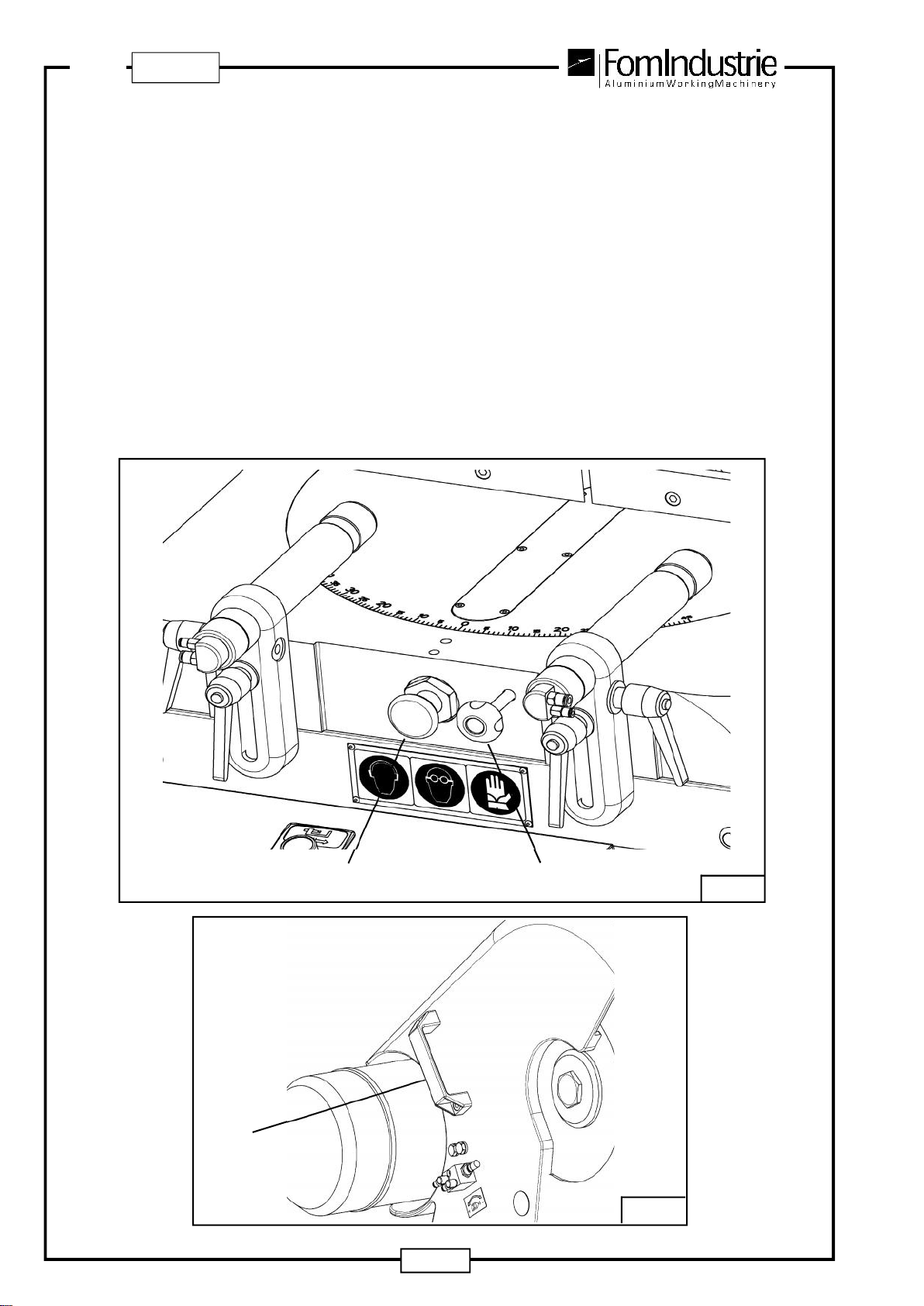
3.1 OTHER PLATES ON THE MACHINE (Fig. 03-02)
1-Safetywearon:earplugs,goggles,gloves
2-Bladerotationdirection
3-Cuttinglubricationflowadjustment

35
SIKAPLUS
GB
3.2 TECHNICALSPECIFICATIONS
• Tungstencarbidesawblade:Ø400mm
• Threephasemotor: 2.2 Kw (3 HP) - 2800 rpm - 230/400V - 50 Hz
• Bladerotationspeed:2800rpm
• Bladespindle:Ø 32 mm
• Motor-bladetransmissionbybelt
• Bladeprotectiveguard
• Cutswith:headat90°
headangledto45°LH,to45°RHandtopositionsinbetween
headangledto45°LHandturnedto90°,to45°Lh(andtopositionsinbetween)
• Headpositioningto90°and45°LH/RHwithconicalpinandself-retainingrelease
• 2pneumaticviceswithsafetyservovalves
• Doubleworkingpressureservocontrolledinlowpressure
• Workingpressure:7bar
• Headdownfeed:hydraulic(adjustabledownfeedspeed,rapidupfeed)-SIKAPLUScodeXZ-10567
manual-SIKAPLUScodeXZ-10568
• Airconsumptionperworkcycle:1.3Nl(XZ-10568)-3Nl(XZ-10567)
• Atomisedcuttinglubrication
• Setupfor theinstallationof chipsandfumesextractionsystem
• Setupforconnectiontorollertable
Suppliedasstandard:
Compressedairgun
Optional:
VerticalLH/RHvice
Kitformicrodroppureoilcuttinglubrication
03-03B
Kg. 170
Overalldimensionsandweight(XZ-10568)
925
1745
03-03A
Kg. 170
Overalldimensionsandweight(XZ-10567)
1131
1565
732
732
36
GB
SIKAPLUS
03-04
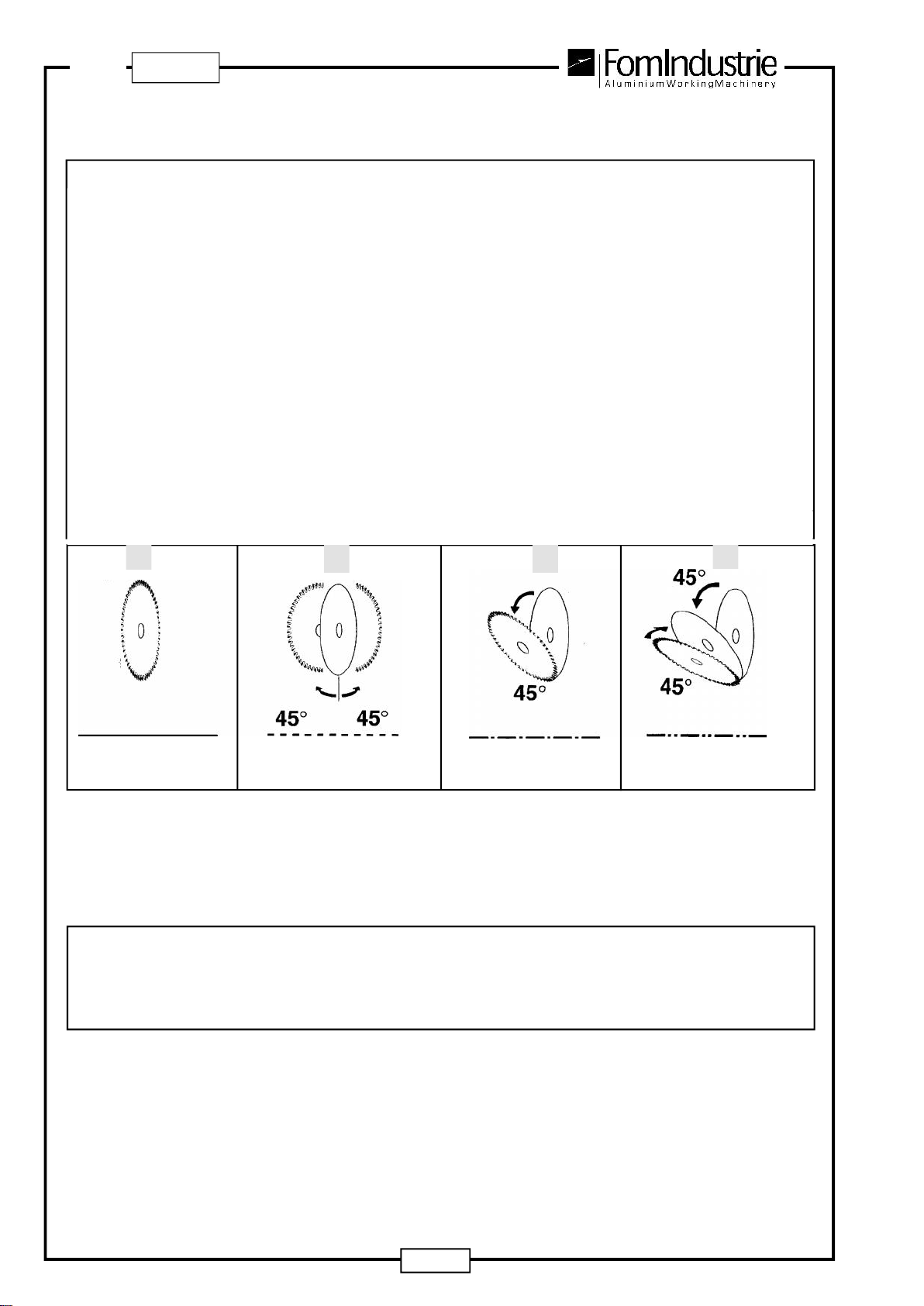
90° head: continuous line Head tilted 45° LH: line-point-
line
Headturned45°LHand/or45°RH:
dash line Headtilted45°LHandturned45°
LH: line - 2 points-line
CUTTINGDIAGRAM
NOISE LEVELS ACCORDING TO ISO 3746
LWA Acousticpowerlevel ........................................................................................... dB(A)110.9
LpA Acousticpowerlevelatoperatorstation .............................................................. dB(A)111.2
3.3 NOISE EMISSION OF THE SIKA PLUS SAWING MACHINE

37
SIKAPLUS
GB
4 HEALTH AND SAFETY DIRECTIONS
4.1 FOREWORD
Everyoperatorofthemachineshouldbefullyawareofthelocationandfunctionofallcontrolsandalsoofmachine
characteristics, therefore they should read this manual thoroughly. Unauthorized tampering or replacement of
machineparts,useoftools,accessories,materialsother thanthoserecommendedbythemanufacturer,canlead
toaccidentsforwhichthemanufacturercannotbeheldresponsible.
4.2 INTENDED MACHINE USE
TheSIKAPLUSsawingmachinehasbeendesignedforcuttingprofilesectionsmadeofaluminium,plasticor
lightalloyprofilesections.
Othermaterialsarenotcompatiblewithitscharacteristics.
WARNING:
Thismachineisnot suitableforworkingin areassubjecttofireor blast risks.
4.3 GENERAL SAFETY WARNINGS
- Theterm“OPERATOR”specificallyreferstothepersonorpersonsentrustedwithinstalling,operating,adjusting,
carryingoutmaintenance,cleaning,repairingandhandlingthemachine;“DANGEROUSAREAS”referstoany
areainsideand/ornearthemachineinwhichthepresenceofanexposedindividualconstitutesarisktothehealth
andsafetyofthatperson;“EXPOSEDINDIVIDUAL”referstoanypersonstandingfullyorpartiallyinadangerous
area.
- Accordingtotheprovisionsof“lightinginworkareas”,theplacewherethemachineisusedmusthavenoareas
inshadow,glaringlights,ordangerousstrobeeffectscausedbythelightingintheworkshop.
- Furthermore,efficientventilationmustbeguaranteedintheworkplacewiththeuseofasuitableextractionsystem
wherenecessary.
- The machine must be operated by skilled staff only and is designed for machining “NON-TOXIC” and “NON
AGGRESSIVE” materials; the use of any products other than these absolves FOM INDUSTRIE from any
responsibilityfordamagecausedtothemachine,personsorproperty.
- Themachinecanworkatambienttemperatures of0 °Cto+ 40°C
- Theremovalofguardsandsafetydevicesisabsolutelyforbidden.
- Theareaswheretheoperatorworksshouldalwaysbekeptclearandcleanfromanyoilresidue.
- Beforesettingtowork,theoperatormusthaveaperfectknowledgeofthelocationandworkingoperationsofall
controlsaswellasthemachinecharacteristics.
- Theworkcommandsmustbecarriedoutbyoneoperatoronly;actionbymorethanoneoperatorisonlyallowed
intheloadingphase.
- Routineandspecialmaintenanceoperationsmusttakeplacewhenthemachineisidleanddisconnected.
- Any work on the pneumatic systems must only be performed after having discharged the pressure inside the
circuit.
- Electricalconnectionsshouldbemadeaccordingtothegeneralinstallationrulesforthepreparationandoperation
ofelectricalsystems.
- Electricalinstallationandconnectionsmustonlybemadebyskilledpersonnel.
NOTE:
Theterm“skilledpersonnel”referstopeopletrainedatspecialcoursesandwithaprevious experience
inthefield.
- Skilledpersonnelmustalsobefamiliarwithfirst-aidtechniquesintheeventofaccident.
- Staffinvolvedinoperating,maintenance,cleaning,inspectionetc.willinanycasehavetocarefullyobservethe
safetyrulesinforceinthe countrywherethe machineis tobeused.
Alloperatorsshoulddressinasuitablemannerfortheworkplaceandforthejobtobecarriedout.
Machineandmaintenanceoperatorsshouldnotwearneckchains,braceletsorrings.

38
GB
SIKAPLUS
4.4 SAFETY DEVICES
1 - Bimanualcontrolvalveforbladedownstroke(onlyonautomaticversion).
2 - 2vicenon-returnsafetyvalves(oneforeachhorizontalvice)
3 - Mobilebladesafetyguard
04-01
2
1
3
4.5 AREAS OF RISK AND RESIDUAL RISKS
Despitethesafetyguardsanddevicesprovidedonthemachine,therearesomeareastobeconsidered“risk” areas
ifmisusedbypersonnel.
Thepictureshowstheareawherecontrolandoperationofthemachinearehandledinstandardoperatingconditions
(guarddown).
That areaposes no risk andis described asthe “OPERATOR CONTROLAREA”.
Risk area, forced evacuation of fumes; it is forbidden for anyone to stand in this area unless the machine has been
connected to an extraction system.
ZONA OPERATORE
OPERATORAREA

39
SIKAPLUS
GB
05-01
A
5 TRANSPORT AND INSTALLATION
Themachineisdeliveredinoneofthefollowingways:
packedonawoodenpallet,packedonawoodenpallet
andincartons,packedonawoodenpalletandina
woodencrate.
Insidethemachine(clearlyinsight),thecustomerwillfind
notonlytheinstructionmanual,butalsoapackcontaining
thetoolkitandtheelementsforanchoringtotheground.
5.1 HANDLING (Fig. 05-01)
Themachine,packedornot,hastobehandledcarefully
andwithsuitableforklift.Whenliftingorpickingupbefore
positioning, make sure not to damage the most fragile
parts,namelycablesorhoses,usingsuitableequipment.
5.2 INSPECTIONS
- Makesurethatenvironmenthasnoareasinshadow,
dazzlingraysordangerousstroboscopiceffectsdue
tolighting.
- Makesurethatnodamageoccurredduringtransport.
- Makesurethatmachine rests evenlyonfloor.
- Make sure that there is enough room around the
machine to carry out all maintenance operations
safelyandeasily.
5.3 POSITIONING AND INSTALLING THE
MACHINE
Afterchoosingtheplace,installationbegins.
Secure the machine to the floor using the two corner
brackets“A”-Fig.05-02suppliedwithit.
Securethebracketstothemachineandfloorasshownin
Fig.05-02below,makesurethatthemachineislevel(if
necessary, place little pieces of plate under the stand)
beforefixingthecornerbrackets).
05-02
40
GB
SIKAPLUS
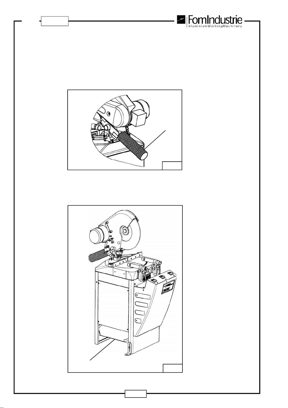
5.4 CHIPSANDFUMESCOLLECTION
Attheback ofthe machinethereisaflexiblehose,forconnectionto anextractionsystemtotake awaytheflying
chipsand fumesproducedbycutting (seeRef.“1”- Fig.05-03).
Primadiallacciarel'aspiratoreallamacchina(direttamenteconuntuboflessibiledidiametro80mm.oppureattraverso
unariduzione),éconsigliabilerimuovereiltubo“1”-Fig.05-03allentandolarelativafascetta.
N.B.Theexhaustermustbeinstalledbytheuserunderhisownresponsibility.
Itisadvisabletofitacontainertocollectchipsandoilresiduefromcuttingwhichshouldbepositionedlaterally
nextto slide“A” (seeFig. 05-04).
1
05-03
A05-04

41
SIKAPLUS
GB
06-01
123
6 CONTROLS
6.1 CONTROL PANEL - SIKA PLUS cod. XZ 10567 (Fig. 06-01)
1 - CLOSE VICES / HEAD DOWNSTROKE - CUT button
2 - OPENVICES button
3 - HEAD DOWNSTROKE - CUT button
6.2 CONTROLS - SIKA PLUS cod. XZ 10568 (Fig. 06-02)
1 - CLOSE VICES/ OPEN VICES button
2 - HEAD DOWNSTROKE- CUT Lever
06-02
1
2
42
GB
SIKAPLUS
7 ELECTRICAL AND PNEUMATIC CONNECTIONS
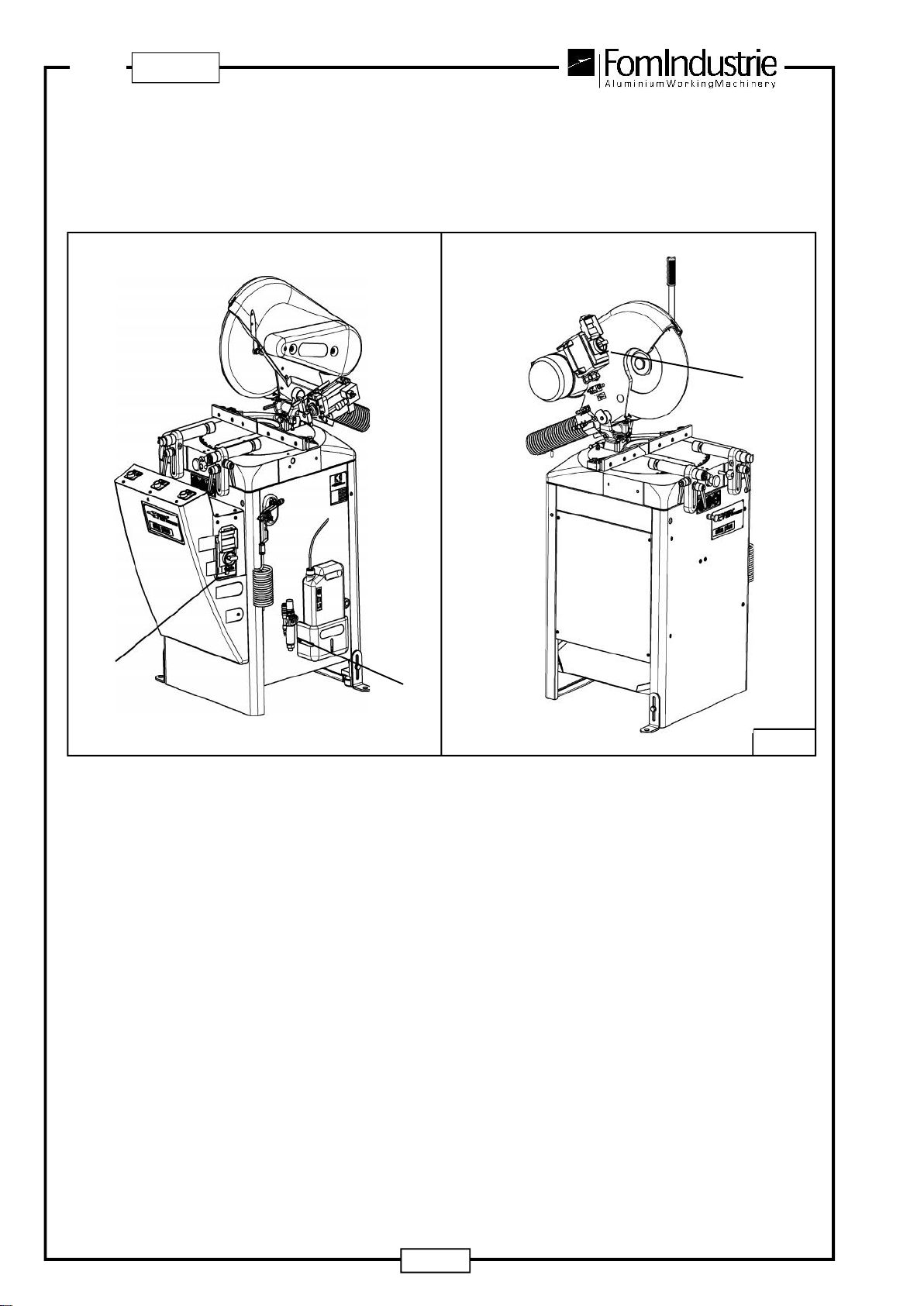
7.1 ELECTRICAL AND AIR CONNECTION COMPONENTS (Fig. 07-01)
1-On/Offswitch
2 - Air intake filter
Beforestarting
Before starting the machine, it must first be checked that the mains power supply is efficient, safe and reliable,
protectedbyanautomaticsupplylineswitchandproperlyearthed.Thisappliesalsotothecompressedairsupply
whichmustbeofsufficientsectionfor therequiredcapacityandavalvefittedsothatthesupplycanbecutofftothe
machine.If the airdistributionlineisof considerable length,then appropriatereleasebarrels must beprovidedat
suitablepointstodrainoffthecondensation.
Beforecarryingoutanyoperationsofthissort,makesurethatthepowersupplyavailableisthesameasthatrequired
bythe machine. Checkthat themain switch(400V -three-phase)isset to0(zero).
Connectiontotheelectricalpowersupply
A-400VTHREE-PHASEpowerlead
Ifthemachinedoesnotalreadycomesuppliedwithplugsforconnectiontothepowersupply(400V),connectthepower
leadstotherelativeplugs.
Protectthepowercableswithadifferentialoverloadcutoutswitch.
Shouldthepowersupplywirebecut,resetconnectionreferringtothewiringdiagram(Cap.11).
Ifthedirectionofbladerotationisnotthesameastheoneshownbythearrowonthemachine,inverttwoofthethree
phasesofthepowersupply.
07-01
12
1
SIKAPLUSAUTOMATIC SIKA PLUS MANUAL
43
SIKAPLUS
GB
07-02
1
7.2 MOTOR STARTING SWITCH - SAFETY DEVICES
Themotorstartingswitch:
Can be locked: when the machine is switched off for maintenance; lock the switch with a padlock to
preventaccidentalstarting.
Ismagneto-thermic: so that it switches off automatically in case of short circuit or overheating; everytime this
occurs,theoperatorshouldcheckthattheelectriccircuitandmotorareinorder.
Hasareleasecoil: thatautomaticallyswitchesoffintheeventofapowercut.Thispreventsthemotorfromstarting
againallofasuddenwhenthevoltagereturns.
NOTE:
Inordertocomplywithspecifictechnicalandsafetydirections,manufacturerssupplythemotorstartingswitchwith
onevoltageonly(forinstanceone-phase230V,three-phase230V,three-phase400V,andsoon).
Inserthoseinfitting“1”- Fig. 07-02

44
GB
SIKAPLUS
8 ADJUSTMENTS
8.1 HORIZONTAL VICESPOSITIONING (Fig. 08-01)
Forbestpositioningofthehorizontalvicesonthesurfaceoftheprofile,themethodsbelowshouldbefollowed:
1) Undoreleasehandle“A” tosetthedistancefromtheprofile.
2) Undoreleasehandle“B” toadjustthevicesassemblybothverticallyandlaterally.
Thehorizontalvicesareequippedwithasafetyvalvetopreventopening:iftheairsupplytothevicefails(whenthey
areclosed)theywillnotopen;whentheairsupplyreturnsthemachinefucntionsarerestored.
A
08-01
B

45
SIKAPLUS
GB
8.2 VERTICAL VICE POSITIONING (OPTIONAL) (Fig. 08-02)
1) Undoreleasehandle“A” tosetthedistancefromtheprofile..
2) Undoscrew“B” toadjustthevicevertically.
Toexcludetheverticalvice,turntap"C".
08-02
A
B
C
46
GB
SIKAPLUS
8.3 CUTTING ANGLES
8.3.1 HEAD ROTATION
TheheadoftheSIKAPLUScanberotatedasfollows:
- From 90° to 45° RH
- From90° to 45°LH
Byfirstundoingknob "1"-Fig.08-03 andthenpullingbutton“2”-Fig. 08-03theheadisfreetorotate.
Usethehandle“3”- Fig.08-04torotatetheheadtotherequiredposition.
Mechanicalendoftravelstopsdeterminesthepositions:
-90°
- 45° RH
- 45° LH
Theintermediatecuttingpositionsareobtained,afterpullingoutbutton“2”-Fig.08-03, byrotatingthebladeusing
thehandle“3”- Fig.08-04.
Thevernierscaleisetchedintotheworktable
Readingofftheanglerequired,securetheheadbytighteningknob“1”-Fig.08-03andreleasingbutton“2”-
Fig.08-03.
08-03
3
2 1
08-04
47
SIKAPLUS
GB
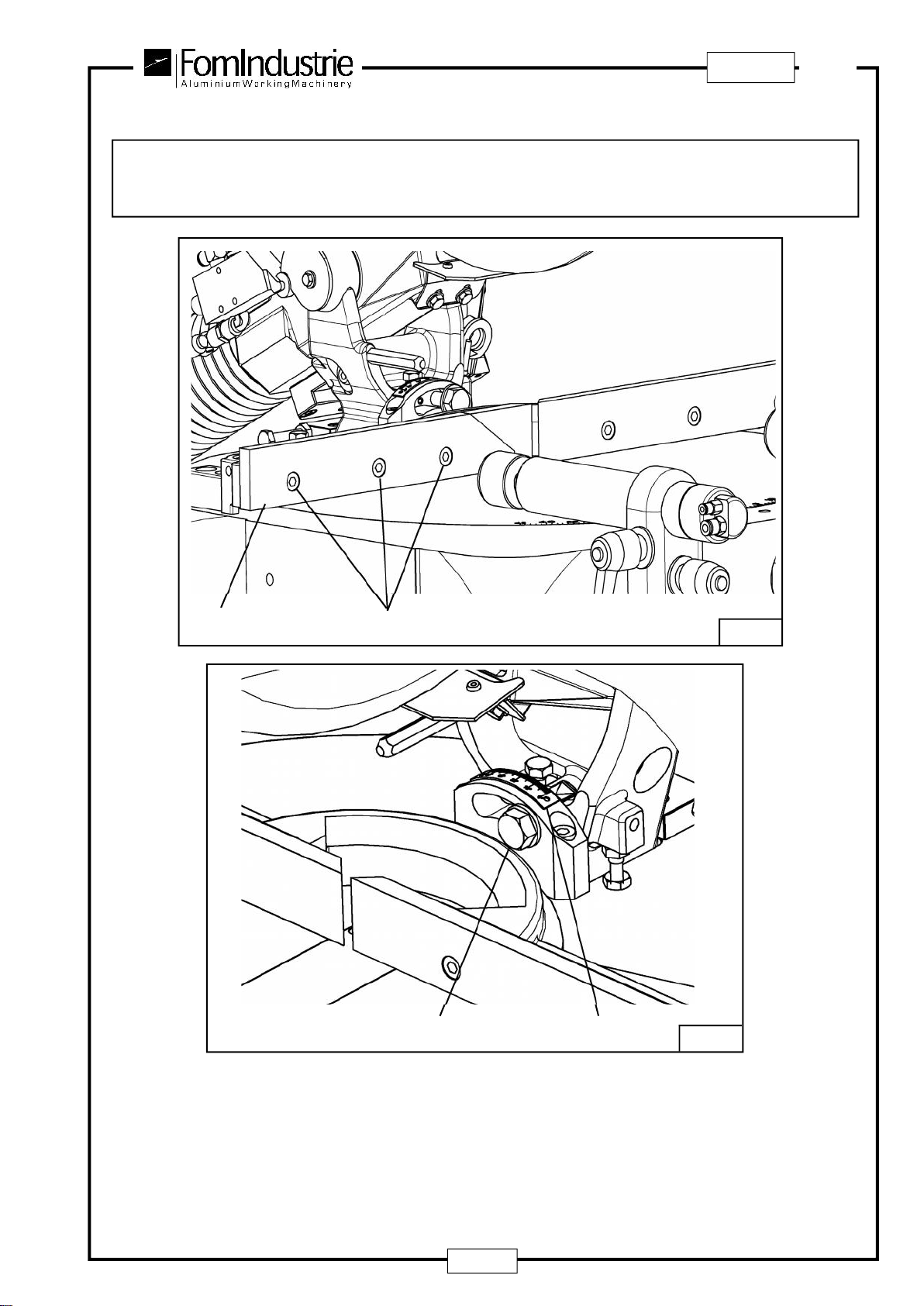
8.3.2 HEAD INCLINATION
IMPORTANT:
beforeincliningtheheadtheLHvicejaw"1"-Fig.08-05,mustberemovedbyundoingthescrews"2"-Fig.
08-05,andsubstitutingitwiththevicejawprovided.
Toinclinetheheadfrom90°to45°totheleftincludingtheintermediateangles,undoscrew"A"-Fig.08-06,thenincline
theheadwhilereadingtheangleoffthevernier"B"-Fig.08-06.
Lastly,tightenscrew"A"-Fig.08-06.
Theheadcanalsoberotatedandinclinedsimultaneouslytotheleft.
08-06
08-05
12
AB
48
GB
SIKAPLUS
08-07
8.4 ADJUSTING THE BLADE LUBRICATION FLOW (Fig. 08-07)
Theflowoflubricantforthebladeisadjustedbythefollowingprocedure
Turningtheknurledknob"A"clockwisedecreasestheflow,turningitcounterclockwiseincreasestheflow.
IMPORTANT:
Intheoiltankforcutting(orblade)lubrication,putonly:
OILFORCUTTINGALUMINIUM.
A

49
SIKAPLUS
GB
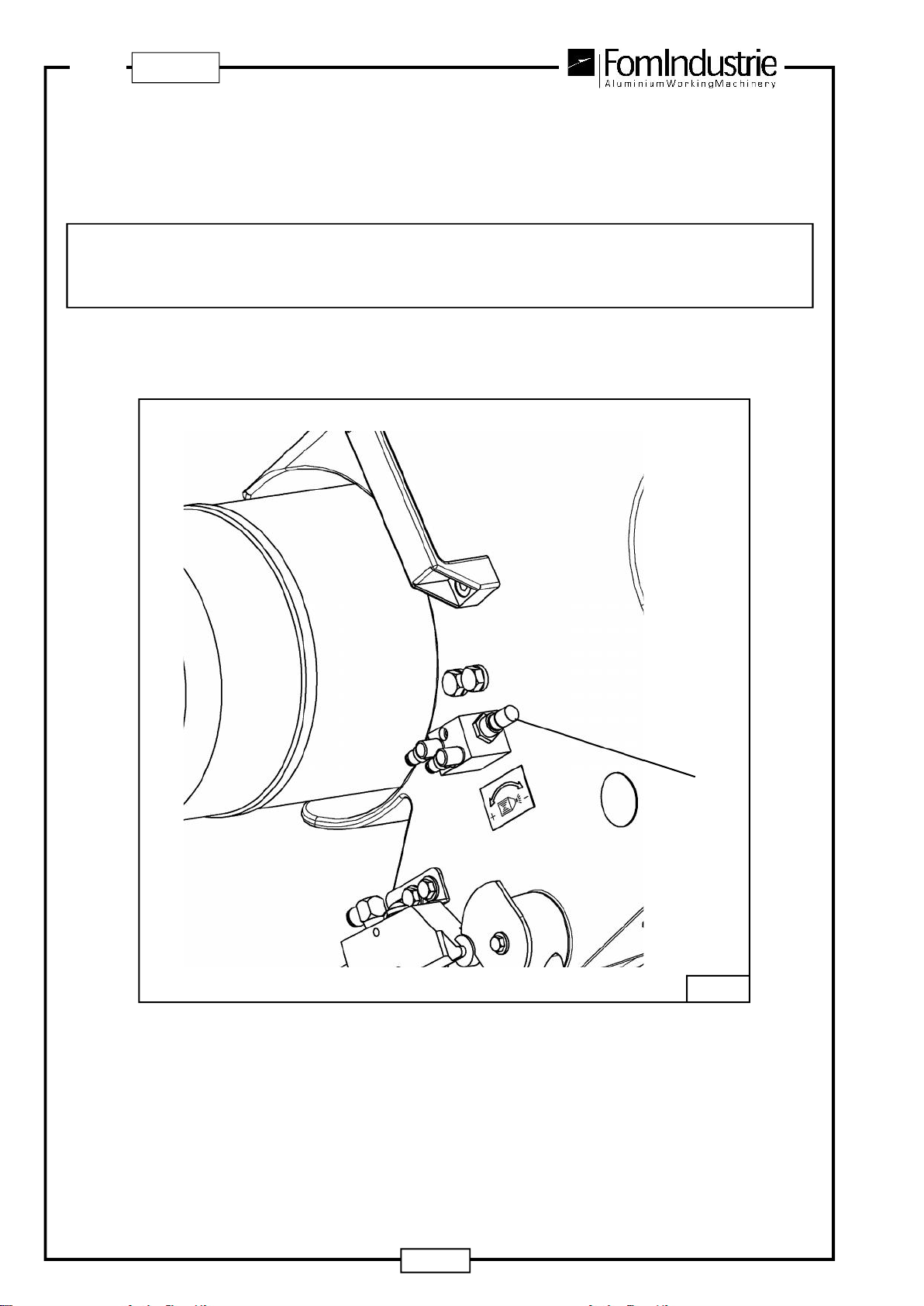
8.5 ADJUSTING THE BLADE DOWN-FEED - SIKA PLUS AUTOMATIC (Fig. 08-08)
Turningknob“A”clockwisedecreasesthebladedown-feedspeed;turningknob“A”counterclockwise increases
thespeed.
8.6 ADJUSTINGTHEBLADEDOWN-FEEDSPEED(RAPID -OPERATINGDOWN-FEED)-SIKA
PLUS AUTOMATIC (Fig. 08-08)
Themachineheadhastwodown-feedspeeds:
- rapid
- operating
Theformerallowsafastapproachtotheworkpiece.
Thelatter(slower)issuitableforcutting.
Loosenscrew“A” andreleasebar“B”asshown.
Whenthebarmeetsthepneumaticmicroswitch“C”,rapidspeedturnstooperatingspeed(slow).
D
CA08-08
NOTE:
“BLADE DOWN FEED SPEED” and “BLADE LUBRICATION FLOW” adjustments are usually set to
standardwhenmachineistestedatthemanufacturer’sworkshop.
B

50
GB
SIKAPLUS
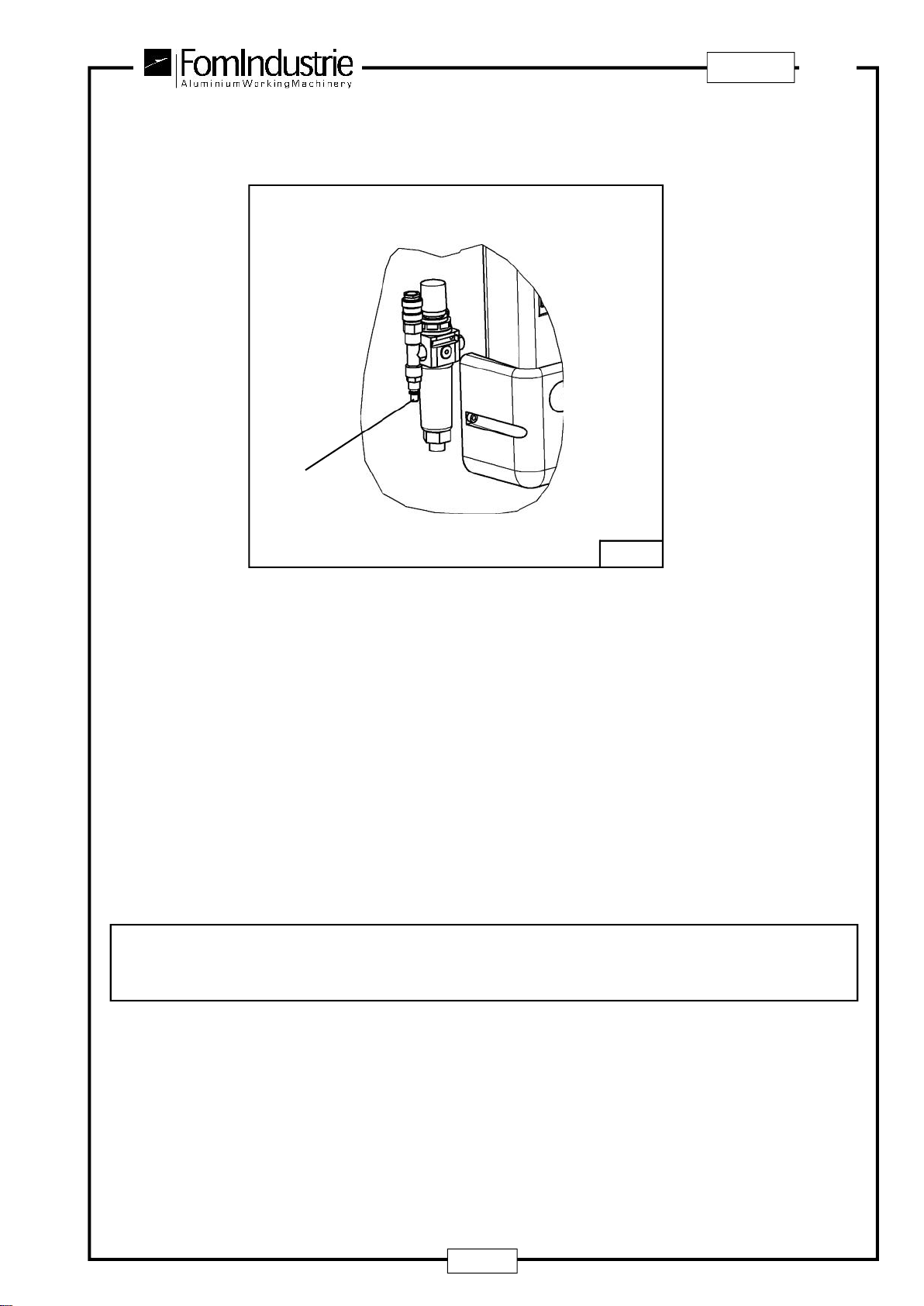
8.7 ADJUSTING THE AIR INTAKE PRESSURE (Fig. 08-09)
Toincreaseordecreasetheairintakepressure,turnknob“A”(liftup,adjustandpushdownagaintosecure).
8.8 ADJUSTMENTS ON THE AIR INTAKE FILTER (Fig. 08-09)
DISCHARGINGCONDENSATION
withoutdisconnectingtheairsupplyhose,pressknob“B” makingsurethattherelativeringisopen.
Thecondensationisinanycasedischargedautomatically(alwayswiththeringopen)eachtimetheairsupplyhose
isdisconnected.
08-09
A
B
Table of contents
Other FOM INDUSTRIE Saw manuals


