STALEX VS-400 User manual
VERTICAL BAND SAW
MODEL: VS-400
VS-500
VS-585
Operating Manual

2
Table of contents
I.INTRODUCTION……………………………………………………………….3
II.INFORMATION ABOUT MAINTENANCE ASSISTANCE…………………3
III. SPECIFICATION……………………………………………………4
IV.DESCRIPTION OF THE MACHINE AND ITS COMPONENTS……… 4
V. INSTRUCTION MANUAL ………………………………………..5-10
VI.INVERTER PARAMETER…………………………………………..11
VII. DRAWING AND PARTS LIST…………………………………………12-21
VIII.ELECTRICAL DRAWING FOR VS-400,VS-500 and VS-585…… .22-24

3
I.INTRODUCTION
The “Operating instructions” are an integral part of the machine and should be
consulted before, during and after the start up of the machine and whenever else
required. The content of these instructions should always be carefully observed.
The observance of the above is the only way to achieve the two fundamental aims of this
manual:
● Optimization of machine performance
● Prevent damage to the machine and injury to the operator
CAUTION: BEFORE INSTALLING THE MACHINE, READ
THE OPERATING INSTRUCTIONS CAREFULLY
II.INFORMATION ABOUT MAINTENANCE ASSISTANCE
2.1 GUARANTEE
● The products are guaranteed against material and manufacturing defects for a period of
12 months from the date of delivery.
● The buyer is only entitled to the replacement of parts which are acknowledged as
faulty: carriage and packing are at the buyer’s. In the event of the above, the following
information should be supplied:
1. Date and number of purchasing document
2. Machine model
3. Serial number
4. Code of any relevant drawings
● Requests for compensation for the inactivity of the machine will not be accepted.
● The guarantee does not cover uses which are not in line with these operating
instructions which are an integral part of the machine. Nor is maintenance covered if
the instructions supplied are not observed.
● The guarantee will not cover machines which have undergone unauthorized
modifications.
● Modification or tampering with the safety devices is strictly forbidden.

4
III. SPECIFICATION
Item No.
388201
388202
388203
Model
VS-400
VS-500
VS-585
Max. Cutting capacity
Height
285mm(11.2”)
310mm(12.2”)
336mm(13.2”)
Width
400mm (15.7”)
500mm(19.7”)
585mm(23”)
Table Size
550x600mm
(21.7”x23.6”)
660x700mm
(26”x27.6”)
660x700mm
(26”x27.6”)
Blade Speed(50Hz)
0~1400rpm
0~1400rpm
0~1400rpm
Length of saw blade
3390-3467mm
3980-4050mm
4430-4520mm
Blade width
3-16mm
3-16mm
6-19mm
Table tilt
R-45°, L-15°
R-30°, L-15°
R-30°, L-15°
Main motor
Grinder motor
1.5Kw(2HP)
0.09Kw(1/8HP)
1.5Kw(2HP)
0.09Kw(1/8HP)
1.5Kw(2HP)
0.09Kw(1/8HP)
Electric welder
2.4KVA
2.4KVA
2.4KVA
Packing Size
108x80x200cm
140x90x220cm
147x95x230cm
N.W./G.W.
310/380 kg
484/548 kg
555/640kg
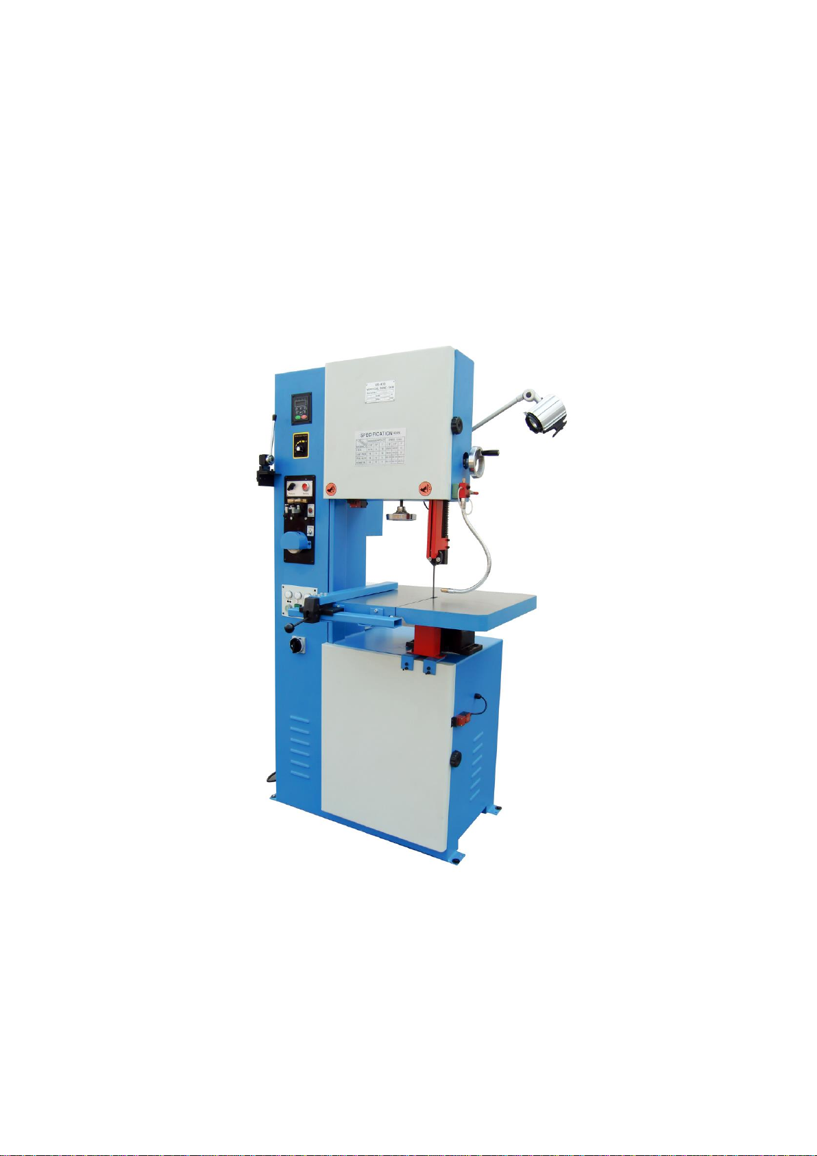
IV. DESCRIPTION OF THE MACHINE AND ITS COMPONENTS
The band sawing machine produced by us has a sturdy frame made from welded and
painted sheet-steel. The upper surface is designed to allow the complete draining away of
the cutting fluid. The band holding bow is made of cast-iron and has generous dimensions,
providing the cutting unit with the necessary strength and precision. The vice unit is made
of cast-iron and clamps the material to be cut securely. The bar-stop device allows the
length required to be preset and a constant level of performance for repeated cuts. The
blade-holding bow is firmly attached to a reduction unit built onto the motor and to the base
by means of a joint which allows 60°rotation to the right. This joint also allows the cutting
movement to advance manually or by falling.
Tank is fitted near the machine table. The main switch is located on the front panel. The
choice of one of the two motor rotation speeds and therefore cutting speed is carried out by
the main switch. The front panel is also fitted with an emergency stop button and a START
button. The control lever,fitted with an ergonomic hand-grip and activation button with
safety release action, reduces fatigue during operation to a minimum. The blade is
protected by a guard with interlock which covers the upper area and the hand wheels and
by two adjustable lower guards which protect the operator from ejected shavings and
coolant. The machine is supplied with a set of service spanners.

5
V. INSTRUCTION MANUAL
PS. Please turn the Regulator to “the lowest speed” position before turning on the machine.
1. The mechanical construction of this machine is illustrated as shown on the Parts List.
2. The adjusting screws, above and under the Band Guides, can be adjusted as long as.
3. The worktable can be titled.
4. This manual has been prepared for the operator who operates, and the maintenance of
the Vertical Saw. The purpose is to promote safety through the use of accepted
operation procedure.
The following instructions in operations and maintenance shall be observed in order to
obtain the maximum efficiency of the unit.
The procedure is shown as follows:
A. Power
B. Sawing material selection
C. Blade selection
D. Blade cutting device
E. Welder
F. Grinder
G. Blade installation
H. Guide rob adjustment
I. Inverter speed selection
J. Air pump
K. Angle cutting
L. Safety and maintenance
M. Inverter parameters
ACTION TAKEN
A. Power
1. First, before operating the machine, be sure to check the voltage which is in accordance
with the power supply system.

6
B. Sawing Material Selection:
Before sawing, the operator must fully understand the quality of the sawing material.
Example: With super high stencil steel, the machine should be run at a slower speed.
Otherwise, the blade will overheat, be worn or broken easily. With thin material, it is
recommended to use a wider blade pitch at high speeds; otherwise, the teeth will be ruined
easily.
C. Blade Selection:
1. Generally, there are three different types of blade. These are used for metal materials
such as steel, brass, iron and aluminum or non-metal such as wood, plastic, rubber and
paper materials.
2. Selection of the blade pitch is essential. As a general rule, the thicker the material the
less teeth per in pitch, and a wider blade should be used.
3. When cutting ‘Radius’ – the smaller the ‘Radius’ the narrower the blade.
4. Refer to the Speed & Pitch Selector guide on the machine for proper radius and pitch.
D. Blade cutting Device: Use the Blade cutter only for cutting blades if you want to
maintain the cutter for a long period of time. Do not use it as a general purpose cutter.
E. Welder: Reference as the following
1. Prepare before welding
a. Cleaning the blades and cut the two ends straight with the cutter. Use grinding wheel
deburring the ends if necessary.
b. Put the blade ends on the clamping points separately, and make sure the two ends
contact closely. Then, turn the clamping handles to outsides and lock the electrode
to blades.
c. Adjust voltage knob according to the blade thickness. The more thickness, the
higher voltage (Turn the knob clockwise for higher voltage). The normal setting is 4
position.
2. Welding operation
a. Use your Thumb to press the Welding Button, then blade change to Red color and
activities electrode driven the blade feed for welding. Please do not release the Weld

7
Button during the welding until the blade back to black color.
3. Tempering operation
a. Press the tempering button until the welding points begin to appear red color. Then,
after the blade back to the normal color, do the previous action again. Repeat this
pressing 5-7 times. Please do not keep pressing over 3 seconds each time. Before
tempering, please release the two clamping points first, then re-fix them in 1.b step.
4. Weld dressing
a. Turn the clamping handles in vertical position and take blade out. Start the grinding
wheel to polish the over parts. Then, the blades can be reused.
8
Maintenance and trouble shooting
1. Maintenances
a. put the voltage adj. knob back to mark of “i” when the machine is not working
b. after half hour working, the machine can only be continue to work when the temperature
is lowing down to the ambient temperature
2. trouble shooting
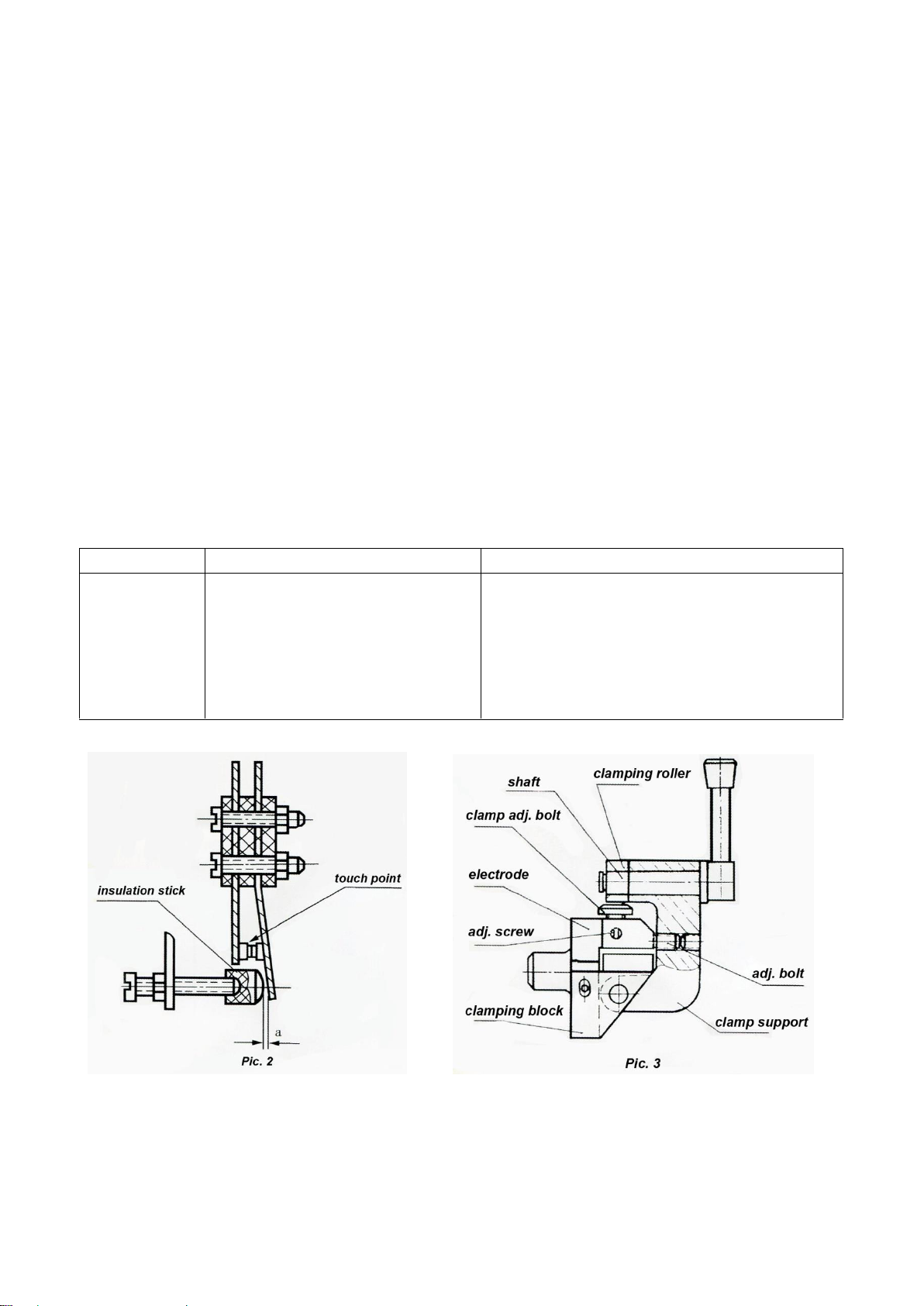
If the cut welding is not work, then open the panel, removal the switch of cut welding
according to picture 2,polish the touch point by sand cloth,, then put on the switch of cut
welding again, at this time, the insulation stick should jack-up the switch of cut welding,
separate the second touch point. According to the time of welding needed to adjust the
distance A. The bigger distance in A, the longer time for welding melt.
Trouble
Possible Reason
Solution
Welding
seam broken
a. Blades welding end is dirty
b. Not proper welding voltage
c. Two ends is not align
d. Two ends do not melt at the
same time.
a. Cleaning the blades with clothes.
b. Increase the welding voltage.
c. Align the blade Two ends.
d. Adjust the “adjusting screw” in the
clamping plate, to align the center of
clamping roller and the bottom bolt.

9
Trouble
Possible Reason
Solution
Blade do not
melt
a. Blade two ends is not
straight and flat
b. Electrode is broken or worn.
c. Cut welding switch not work
d. Blade two ends do not
contact.
e. Blade clamping points have
rust.
a. Cut the two ends straight and flat.
b. Repair the electrode.
c. Polish the touch points of the switch
by sand cloth.
d. Re-cut the blade two ends.
e. Remove the rust by sand cloth.
Blade cannot
clamp tightly
The distance between the
clamping roller and bottom bolt
is big.
Adjust the “adjusting screw” in the
clamping plate, to align the center of
clamping roller and the bottom bolt.
F. Grinder:
The grinder is used for grinding off both ends of the cut blade on the surface so that the
blade can be welded together easily. Note: Do not exceed in running the grinder for more
than 30 minutes at a time.
G. Blade Installation:
First turn off power and open the safety covers; then take off the old blade by turning the
blade tension hand wheel and removing the guide bar from the table. Replace the blade
with the teeth in the downward position. Be sure the safety covers have been closed.
H. Guide Rod Adjustment:
Adjustment to the guide rod is very essential. There are two rods: Top and Bottom. Only the
top one can be adjusted about 1mm above the sawing working piece. Note: If the
adjustment is made higher, the blade will be bent, so the support block of the supporting
blade should also be adjusted in line with the blade width and thickness. When making
adjustments, the power shall be shut off, and the support block shall be right in the middle
position of the rear of the blade teeth (neither loose nor tight).
I. Inverter Speed Selection and Operating:
J. See the Speed & Pitch selector on the front of your machine.
Operation method: Switch on; then turn motor starter switch on, and then adjust to
desirable speed by speed adjusting knob.
K. Air pump:
Voltage: 220V/60HZ Current: 0.5mA Flow rate:10-12(L/min)

10
Pressure: 0.20Kg/cm2 Type of fluid: Air
L. Angles Cutting:
1. Declination sawing: Loose table nuts; adjust the table into the desirable position,
and retighten the nuts.
2. “R” shape sawing: Turn slowly because the sawing edge must remain flat, straight
and smooth.
3. Smaller working piece sawing: Be careful to push or pull the work piece by using a
wood block (not by hand); otherwise, the operator may get hurt.
4. Internal contour: First , drill a hole through the work piece large enough to fit the
blade through. Weld the blade ends together (grinding smooth). Reinstall blade on
wheels and make normal blade adjustment. Begin to perform contour sawing.
5. Working Speed: When sawing, the speed shall remain the same (neither fast nor
slow); otherwise, blade breaking may occur.
M. Safety and Maintenance:
1. Be sure that the safety cover and the wheel doors are always closed before turning
on the machine.
2. The band saw shall be installed in a dry place in order to avoid electrical shock.
3. Make sure the machine is grounded properly (green wire to ground).
4. After installing a new saw blade, start the motor and keep the blade turning without
load about 1 minute; then proceed to cutting the work piece
5. Upon sawing, if any unusual noise, smell or blade breakage occurs, operator should
immediately switch off the power.
6. Maintenance: After operating, switch the machine off. After clearing the machine,
take away the chips, and slightly lubricate the surface of the machine and all joints
to keep them from rusting.

11
VI.INVERTER PARAMETER:
1.Consumers are not allowed to adjust the parameters without authorization .(In case that
machine failure is caused by any consumer who alters any parameter without authorization,
the consumer should be responsible for the failure.)
2.Inverter parameters are only provided for the qualified technician.
MAINTENANCE AND CAUTIONS
Remarks:
1. This welding device isn’t recommended to weld saw blades made of high speed steel.
Continuous welding should be avoided. After being used several times, turn the welder
off for 15 minutes rest so that the transformer will not suffer from overheat. In case that
transformer becomes overheated, the temperature controller will actuate the breaker.
Reuse will not be allowed until the transformer cools down.

12
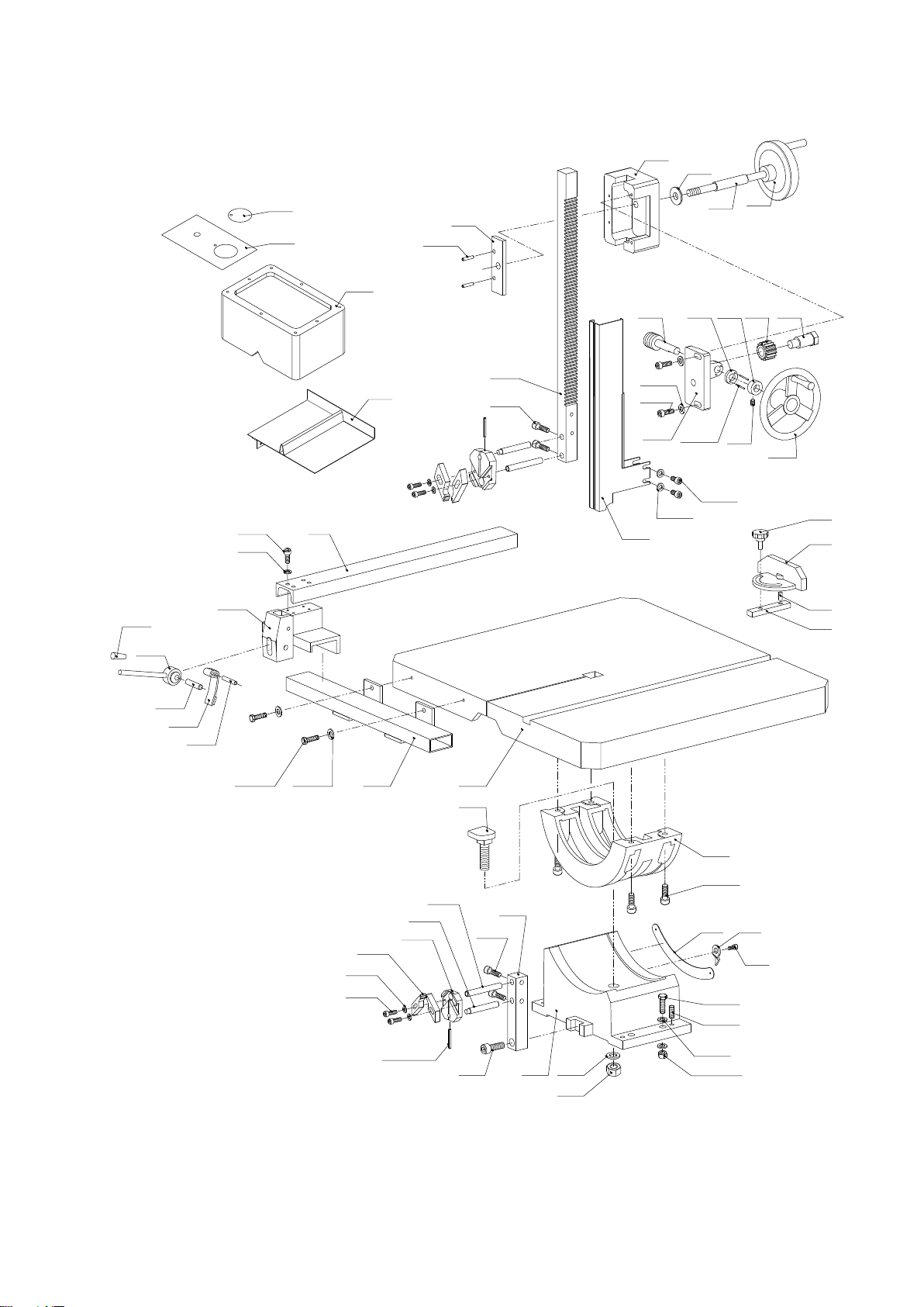
VII. DRAWING AND PARTS LIST
VS-400 packing list and drawing
Item
Description
Qty
Item
Description
Qty
1
Low door
1
41
Wood brush
1
2
Bolt M6X12
2
42
Bolt M5X20
4
3
Nut M6
2
43
Big washer 5
4
4
Pin
4
44
Block
4
5
Bolt M5X16
4
45
Blade block material seat
2
6
Washer 5
4
46
Blade stay bar
2
7
Left seat board
1
47
Blade back bar
2
8
Right seat board
1
48
Bolt M8X16
2
9
Bolt M6X8
2
49
Blade down guard
1
10
Blade down cover
1
50
Bolt M10X40
2
11
Bolt M5X10
4
51
Down seat
1
12
Panel
1
52
Washer 16
1
13
Up door
1
53
Nut M16
1
14
Blade weld
1
54
Big washer 8
8
15
Bolt M5X10
6
54.1
Nut M8
4
16
Bolt M8X16
2
55
Bolt M8X16
4
17
Blade cutter
1
56
Bolt M8X35
4
18
Bolt M5X10
4
57
Bolt M5X8
1
19
Transducer display
1
58
Finger
1
20
Transducer small fixed board
1
59
Scale
1
21
Machine stand
1
60
Bolt M8X25
4
22
Transducer
1
61
Up seat
1
23
Transducer seat board
1
62
bolt
1
24
Bolt M5X10
4
63
Working table
1
25
Washer 4
4
64
Gauge
1
26
Elec. box
1
65
Washer 6
2
27
Big washer 6
4
66
Bolt M6X20
2
28
Bolt M6X12
1
67
Pin shaft
1
29
Working light
1
68
Press sheet
1
30
Working light seat
1
69
Pin shaft
1
31
Bolt M6X10
4
70
Eccentric handle
1
32
Block
1
70.1
Handle sleeve BM8X32
1
33
Coolant nebulizer
1
71
Seat
1
34
Bolt M4X20
2
72
Washer 6
4
35
Back cover
1
73
Bolt M6X16
4
36
Bolt M6X12
10
74
Bar
1
37
Big washer 6
10
75
Bolt M8X16
2
38
Door bar
2
76
Gear sheet
1
39
Bolt M6X16
2
77
Blade protect cover
1
40
Water box
1
78
Washer 6
4

13
Item
Description
Qty
Item
Description
Qty
79
Bolt M6X12
4
118
Flange
1
80
Handle wheel
1
119
Bearing 6206-2Z
2
81
Bolt M6X6
1
120
Block 62
2
82
Elasticity pin 2X14
2
121
Handle
1
83
Gear seat
1
122
Bearing 51201
2
84
Bolt M6X25
2
123
Bolt washer
2
85
Big washer 6
2
124
Elasticity pin 3X24
2
86
Worm
1
125
Lead Screw
1
87
Washer
1
126
Bolt M8X25
2
88
Bolt washer
1
127
Washer 8
2
89
Slanting gear
1
128
Shaft seat
1
90
Shaft bolt
1
129
Up wheel seat
1
91
Handle φ80Xφ10
1
130
Right wash board
1
92
Screw
1
131
Up wheel seat
1
93
Washer
1
131.1
Spring pin 3X24
1
94
Up guard seat
1
132
Left washer board
1
95
Press board
1
133
Elasticity washer 8
4
96
Elasticity pin 4X20
2
134
Bolt M8X25
4
97
Bolt M10X16
3
135
Up wheel
1
98
Big saw wheel
1
136
Up wheel shaft
1
99
Small saw wheel
1
137
Bearing 6304-2Z
2
99.1
Bolt M10X16
2
138
Elasticity washer 16
1
100
Motor seat board
1
139
Nut M16
1
101
Bolt M8X25
4
140
Blade 3450
1
102
Washer 8
4
141
Coolant box Seat
1
103
Adjust seat
1
142
Coolant Box
1
104
Nut M8
2
143
Coolant box Cover
1
105
Bolt M8X50
2
144
Cover
1
106
Bolt M8X20
2
107
Motor
1
108
Strap A-1160
2
109
Big saw wheel
1
109.1
Bracket
1
110
Bolt M8X25
4
111
Key 8X50
2
112
Bolt M12X30
2
113
Shaft washer 30
1
114
Down wheel shaft
1
115
Block cover
1
116
Bolt M10X45
4
117
Adjust bolt
4
14

15
16

17
VS-500 and VS-585 packing list and drawing
Item
Description
Qty
Item
Description
Qty
1
Low door
1
38
Water box
1
2
Bolt M6X12
2
39
Wood brush
1
3
Nut M6
2
40
Bolt M5X20
4
4
Pin
4
41
Big washer 5
4
5
Bolt M5X16
4
42
Block
4
6
Washer 5
4
43
Blade block material seat
2
7
Left seat board
1
43.1
Spring pin 3X18
2
8
Right seat board
1
44
Blade stay bar
2
9
Bolt M6X8
2
45
Blade back bar
2
10
Down blade cover
1
46
Bolt M8X16
2
11
Bolt M5X10
4
47
Blade down guard
1
12
Panel
1
48
Bolt M10X40
2
13
Up door
1
49
Down swivel base
1
14
Blade weld
1
50
Washer 16
1
15
Bolt M5X10
6
51
Nut M16
1
16
Bolt M8X16
2
52
Big washer 10
8
17
Blade cutter
1
52.1
Nut M10
4
18
Bolt M5X10
4
53
Bolt M10X16
4
19
Transducer display
1
54
Bolt M10X40
4
20
Small fixed board of Transducer
1
55
Bolt M5X8
1
21
Machine frame
1
56
Finger
1
22
Transducer
1
57
Scale
1
23
Seat board of Transducer
1
58
Bolt M10X30
4
24
Bolt M5X10
4
59
Up swivel base
1
25
Washer 5
4
60
Big head bolts
1
26
Elec. box
1
61
worktable
1
27
Big washer 6
6
62
Gauge
1
28
Bolt M6X12
6
63
Washer 6
2
29
Working light
1
64
Bolt M6X20
2
30
Block
1
65
Pin shaft
1
31
Coolant nebulizer
1
66
Press sheet
1
32
Bolt M4X20
2
67
Pin shaft
1
33
Back cover
1
68
Eccentric hand
1
34
Bolt M6X12
12
68.1
Handle sleeve BM8X32
1
35
Big Washer 6
12
69
Seat
36
Door Bar
2
70
Washer 6
4
37
Bolt M6X16
2
71
Bolt M6X16
4

18
Item
Description
Qty
Item
Description
Qty
72
Gate
1
111
Motor
1
73
Bolt M8X16
2
112
Belt A-1750
2
74
Rack
1
113
Big saw wheel
1
75
Blade protect cover
1
113.1
Bracket
1
76
Washer 6
4
114
Bolt M8X25
4
77
Bolt M6X12
4
115
Flat key 12X50
2
78
Handle wheel
1
116
Checking ring 40
1
79
Bolt M6X6
1
117
Low wheel shaft
1
80
Elasticity pin 3X14
2
118
Bolt M12X55
4
81
Gear seat
1
119
Leveling bolt
4
82
Bolt M6X25
2
120
Flange
1
83
Big washer 6
2
121
Bearing 6208-2Z
2
84
Worm
1
122
Checking ring 80
2
85
Washer
1
123
Spacer bush
1
86
Bolt washer
1
124
Spacer bush
1
87
Slanting gear
1
125
Handle wheel
1
88
Shaft bolt
1
126
Bearing 51202
2
89
Handle
1
127
Spacer sleeve
2
90
Screw
1
128
Spring pin 4X30
2
91
Washer
1
129
Lead screw
1
92
Up guard seat
1
130
Bolt M8X30
2
93
Press board
1
131
Bolt 8
2
94
Elasticity pin 4X20
2
132
Axle seat
1
95
star grip knob Φ10XΦ40
1
133
Up wheel seat
1
96
Promote seat
1
134
End cover
2
97
Round pin 8X20
1
135
Bolt M10X20
2
98
Sliding plate
1
136
Sliding seat
1
99
Bolt M12X30
2
137
pressing plate
2
100
Washer
2
138
Bolt M10X25
8
101
The pulley
1
139
Upper belt wheel
1
102
Bolt M8X12
2
140
Up wheel shaft
1
103
Small pulley
1
141
Bearing 6207-2Z
2
104
Motor seat board
1
142
Spacer bush
1
105
Bolt M8X25
4
143
Check ring 72
1
106
Washer 8
4
144
Blade 4050
1
107
Adjusting bar
1
145
Coolant box Seat
1
108
Nut M8
2
146
Coolant Box
1
109
Bolt M8X50
2
147
Coolant box Cover
1
110
Nut M8X20
2
148
Cover
1

19
23
1
4(4)
7
5(4)
9(2)
10 12
11(4)
2(2)
3(2)
6(4)
8
13
14
15(6)
16(2)
17
19
20
21
18(4)
22 24(4)
25(4)
26 27(6)
28(6)
29
30
31 32(2)
33
34(12)
35(12)
36(2)
37(2)
38
39
20
68.1
95
96
97
98
146
147
148
145
52.1(4)
74
75
76(4)
77(4)
81
83(2)
82(2)
80(2)
84 85 86 87 88
78
79
89
90
91
92
93
94(2)
40(4)
41(4)
42(4)
43(2)
44(2)
45(2)
43.1(2)
46(2)
47
48 49 50
51
52(8)
53(4)
54(4)
56
55
57
58(4)
59
60
6162
63(2)64(2)
65
66
67
68
69
70(4)
71(4) 72
73(2)
This manual suits for next models
5
Table of contents
Other STALEX Saw manuals


Popular Saw manuals by other brands

Festool
Festool KS 60 E Original instructions

Makita
Makita LS1019 instruction manual

Bauer
Bauer 20211MH-B Owner's manual & safety instructions

DeWalt
DeWalt DCS7485 Original instructions

Rikon Power Tools
Rikon Power Tools 10-321 owner's manual

PrimAster
PrimAster KZS1500 Translation of original instruction manual


