FOM INDUSTRIE BLITZ User manual

10-13
MANUALE USO-MANUTENZIONE
USEANDMAINTENANCEMANUAL
BLITZ
ITRONCATRICE Ø 500 MM / Ø 550 MM / Ø 600 MM A DUE TESTE CON CONTROLLO ELETTRONICO
DELLAINCLINAZIONE
I GB
GB
DUALHEADØ500mm / Ø 550mm/ Ø 600 mm SAWINGMACHINE WITH ELECTRONICANGLESETTING
Vers. 3.0.0

G BG B
G BG B
G B 1 ... 92


1
BLITZ G BG B
G BG B
G B
BLITZ
USE AND MAINTENANCE
MANUAL
SPARES CATALOGUE
TRANSLATION OF
ORIGINAL INSTRUCTIONS

2
G BG B
G BG B
G B BLITZ
CONTENTS
1 GENERALWARNINGS................................................................................................................... 3
1.1 INTRODUCTION ............................................................................................................................. 3
1.2 WARRANTY ................................................................................................................................... 3
2 GENERALINFORMATION .............................................................................................................. 4
2.1 FOREWORD .................................................................................................................................. 4
2.2 IDENTIFICATIONAND CERTIFICATIONPLATE ............................................................................ 5
2.3 PLATES ON THE MACHINE .......................................................................................................... 6
3 OVERALLDIMENSIONS ................................................................................................................ 7
3.1 CUTTINGDIAGRAM ....................................................................................................................... 8
3.2 TECHNICALSPECIFICATIONS ..................................................................................................... 9
3.3 BASICMACHINEVERSION COMPONENTS................................................................................ 10
3.4 SOUND EMISSION OF THE BLITZ SAWING MACHINE ............................................................... 11
4 HEALTHANDSAFETYSTANDARDS........................................................................................... 12
4.1 FOREWORD ................................................................................................................................ 12
4.2 INTENDED MACHINEUSE .......................................................................................................... 12
4.3 SAFETY WARNINGS ................................................................................................................... 12
4.4 SAFETY DEVICES ....................................................................................................................... 14
4.5 RISK AND RESIDUAL RISK AREAS - 1 ....................................................................................... 15
4.6 RESIDUAL RISK AREAS - 2 ........................................................................................................ 17
5 TRANSPORTANDINSTALLATION ............................................................................................... 19
5.1 HANDLING ................................................................................................................................... 19
5.2 CHECKS ...................................................................................................................................... 20
5.3 MACHINEPOSITIONINGANDINSTALLATION ............................................................................ 20
5.4 LEVELLING ..........................................................................................................................26
5.5 FIXING TO THE GROUND................................................................................................. ....30
5.7 CHECKINGTHE ALIGNMENT OF THEMOBILE HEAD ROLLER TABLE ..................................... 31
6 CONTROLS .................................................................................................................................. 32
7 ELECTRICALANDPNEUMATICCONNECTION .......................................................................... 35
8 PROCEDUREFOR START UP AND MACHINING ........................................................................ 37
9 ADJUSTMENTS ............................................................................................................................ 39
9.1 BLADES FEED RATE................................................................................................................... 39
9.2 REGULATING THE FLOW OF LUBRICANT TO THE BLADES ...................................................... 40
9.3 VICE - POSITIONING / ADJUSTMENTS ...................................................................................... 41
9.4 MINIMUMCUT .............................................................................................................................. 46
9.5 CUTTINGANGLES ....................................................................................................................... 49
9.6 CUTTINGPROCEDURE ............................................................................................................... 49
9.7 SAW BLADE ................................................................................................................................ 49
9.8 PROFILEPOSITIONING ............................................................................................................... 50
9.9 CLAMPINGPROFILES ................................................................................................................. 51
9.10 ADJUSTINGTHEPROFILEHEIGHTMEASURER(IFPRESENT) ................................................ 52
9.11 CALCULATINGTHECUTTINGLENGTH ....................................................................................... 53
9.12 CUTS AT EXTERNAL ANGLES OF LESS THAN 30° - SPECIFIC RULES .................................... 54
9.13 RETRACTABLEMIDDLEPROFILESUPPORT(OPTIONAL) ........................................................ 55
9.14 CUTS WITH THE STEP-BY-STEP KIT (OPTIONAL) .................................................................... 58
10 MAINTENANCE ............................................................................................................................ 60
10.1 DAILYMAINTENANCE ................................................................................................................. 60
10.2 PERIODICMAINTENANCE .......................................................................................................... 61
10.3 FITTING A NEW BLADE .............................................................................................................. 63
10.4 FITTING A NEW PRESSURE SWITCH ........................................................................................ 65
10.5 FITTING NEW SOLENOID VALVES ............................................................................................. 66
10.6 FITTINGA NEWREMOTECONTROL SWITCH ........................................................................... 67
10.7 CHANGING THE PADS ON THE VICES ....................................................................................... 68
10.8 FITTING A NEW HORIZONTAL VICE CYLINDER......................................................................... 69
10.9 FITTING A NEW VERTICAL VICE CYLINDER ............................................................................. 70
10.10 CLEANING THE VICE CYLINDER STOP VALVE ......................................................................... 72
10.11 SUBSTITUTINGTHECHIPSCONVEYOR BELT ........................................................................... 73
11 PROBLEMS - CAUSES - REMEDIES........................................................................................... 79
12 DISPOSAL OF THE MACHINE ..................................................................................................... 82
13 ELECTRICALANDPNEUMATICDIAGRAMS............................................................................... 83
14 ORDERINGSPAREPARTS.......................................................................................................... 84

3
BLITZ G BG B
G BG B
G B
1 GENERAL WARNINGS
Before putting the machine into service all the technical instructions given in this manual must be observed
and all the indications shown must be scrupulously followed.
This manual and all the literature enclosed with it must be kept in an easily accessible place known to all
operators and staff entrusted with maintenance operations.
1.1 INTRODUCTION
The BLITZ has been specifically designed for sawing profiles in aluminium or light alloy.
The machine has been specifically designed to be used by a single operator.
WORKING PRINCIPLE:
- Once a profile is placed on the work tables of the two heads, a pneumatic circuit activates the horizontal
and vertical vices that clamp the profile in place.
- Twomotors drive the rotationalmovement of the respectivesaw blades. Operatedbybuttonson the control
console, the blades come out, cut the profile and return automatically.
- Cutting is possible at external angles from 90° to 12° for BLITZ 55 (10° for BLITZ 50, 20° for BLITZ 60L)
and from 90° to 45° internally.
- When cutting is complete the vices open again to allow another profile to be positioned for the next cut.
The instructions for the various pieces of electronic equipment supplied with the models which BLITZ can be
used with are enclosed with this instruction manual as separate publications.
1.2 WARRANTY
The company guarantees that this machine has been tested under peak running conditions with excellent
results. This warranty is valid for a period of 12 months and covers construction materials and defects only.
The customer has only the right to claim for replacement of faulty parts, excluding the cost of carriage and
packaging and complete machine replacement. This warranty does not therefore cover any damage caused
by dropping, tampering or improper machine operation, by disregard of maintenance instructions given in the
instruction manual, or by faulty handling by the operator. No compensation may be claimed for any periods of
machine inactivity. This warranty is not binding unless all payment conditions have been met.
The cost of service assistance, together with the cost of spares used is not covered by the warranty. These
must be paid directlyto the service technician who will issue a maintenance slip tobe later followed by a regular
invoice.
Maintenance charges and the cost of the spares used are taken from the Price List in force at the time.
4
G BG B
G BG B
G B BLITZ
2 GENERALINFORMATION
2.1 FOREWORD
This manual contains the instructions for use and maintenance as well as the drawings and instructions for
obtainingsparepartsfortheBLITZsawing machine manufactured by FOMINDUSTRIE.Themanualcontains
all the necessary information for correct installation and a description of how the machine works.
All information regarding maintenance procedures and adjustments is also given.
WARNING
- All transport, installation, use, routine and periodic machine maintenance must be carried out solely by
skilledpersonnel.
- The term “OPERATOR” refers to the person or persons entrusted with installing, operating, adjusting,
performing maintenance, cleaning, repairing and handling the machine.
IMPORTANT
- AlltheUseandMaintenanceoperationsforthemachinewhicharenotdescribedinthismanualarecontained
in the relative publications enclosed with it.

5
BLITZ G BG B
G BG B
G B
2.2 IDENTIFICATION AND CERTIFICATION PLATE
The figure 02-01 shows the ID plate and its location on the machine.
N.B. The type, code and serial number marked on the plate, must be quoted any time the Manufacturer is
contacted for information or when ordering spare parts.
02-01
6
G BG B
G BG B
G B BLITZ
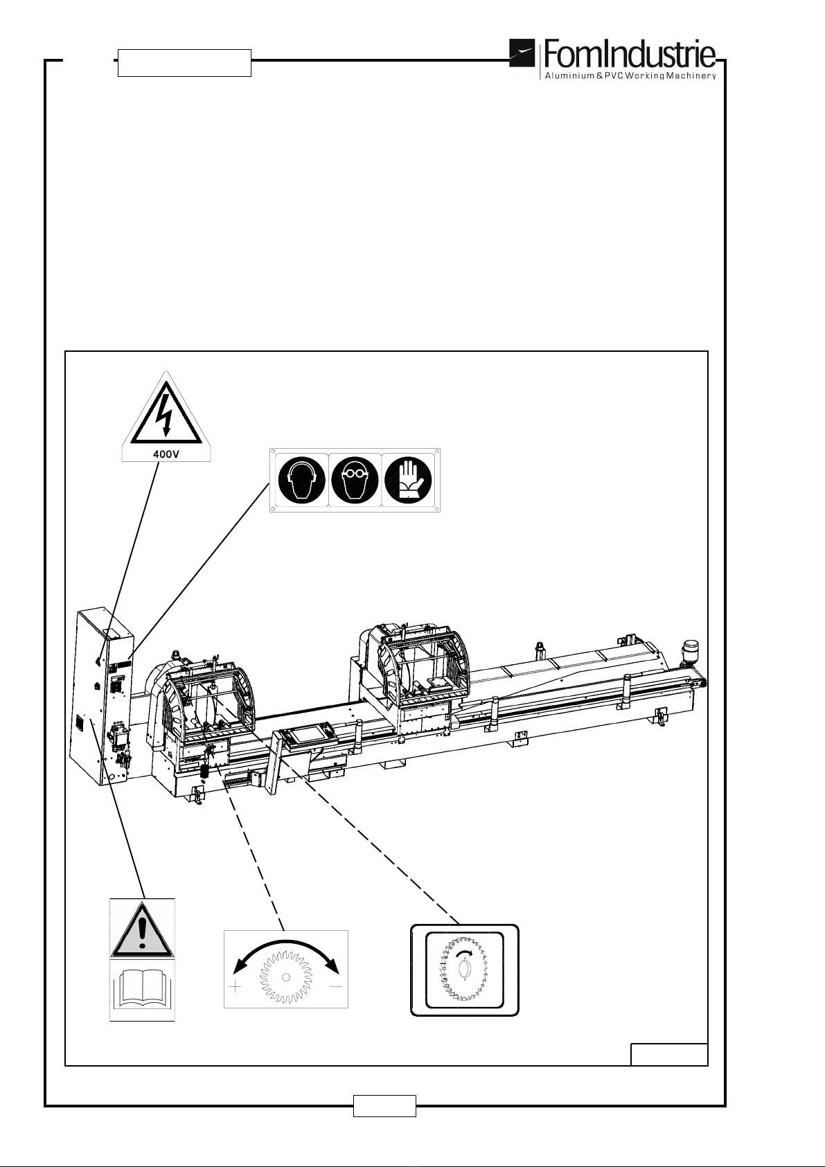
2.3 PLATES ON THE MACHINE (Fig. 02-02)
1 - N.2 “Direction of blade rotation” warning plates
2 - N.1 “DANGER. HIGH VOLTAGE” (400 Volts) warning plate
3 - N.1 “GOGGLES/GLOVES/EAR DEFENDERS" safety wear plate
4 - N.2 “Blade exit speed adjustment” plates
5 - N.1 “Indication of instruction manual located inside electrical cabinet” warning plate
02-02
4
3
2
1
5
7
BLITZ G BG B
G BG B
G B
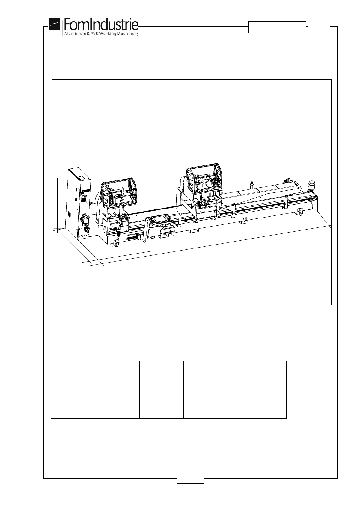
3 OVERALL DIMENSIONS (Fig. 03-01)
m. 5 7050 2090 2070 2400
m.6.6 8630 2090 2070 2600
WORKING
CUT WEIGHT
KG
LPH
Total dimensions with mobile head roller table fully out: L + 2200 mm.
03-01
L
P
H
8
G BG B
G BG B
G B BLITZ
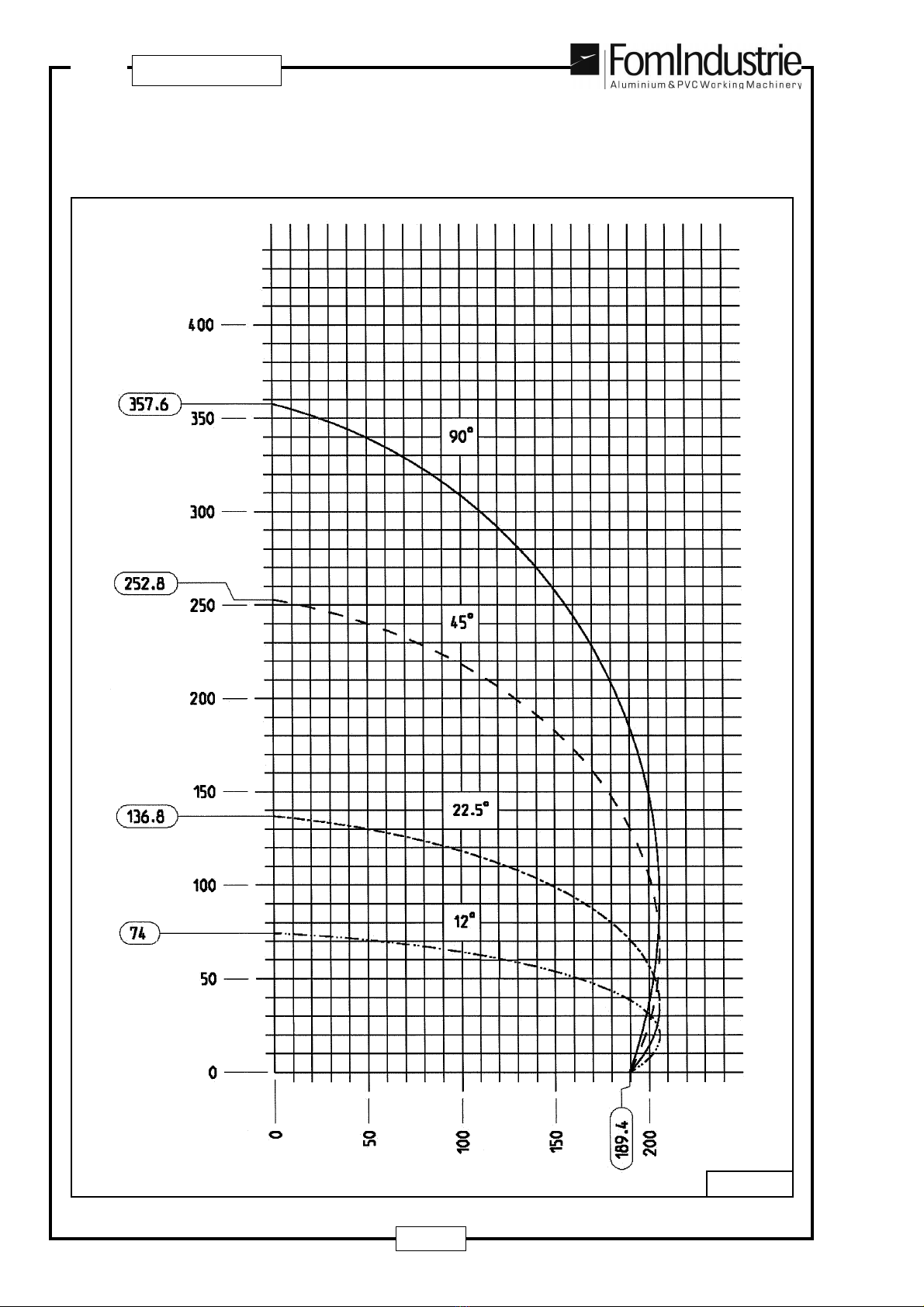
3.1 CUTTINGDIAGRAM
Cutting diagram - BLITZ 55 (FIG. 03-02)
Thecutting diagram with the blade Ø 550 mm. illustrates the machine cutting capacity with the blade set at 90°,
withthebladesetat45°internal/external,withthebladesetat22,5°externalandwiththediscsetat12°external.
03-02

9
BLITZ G BG B
G BG B
G B
03-03
Cutting diagram - BLITZ 50 (FIG. 03-03)
Thecutting diagram with the blade Ø 500 mm. illustrates the machine cutting capacity with the blade set at 90°,
withthebladesetat45°internal/external,withthebladesetat22,5°externalandwiththediscsetat10°external.
10
G BG B
G BG B
G B BLITZ
03-04
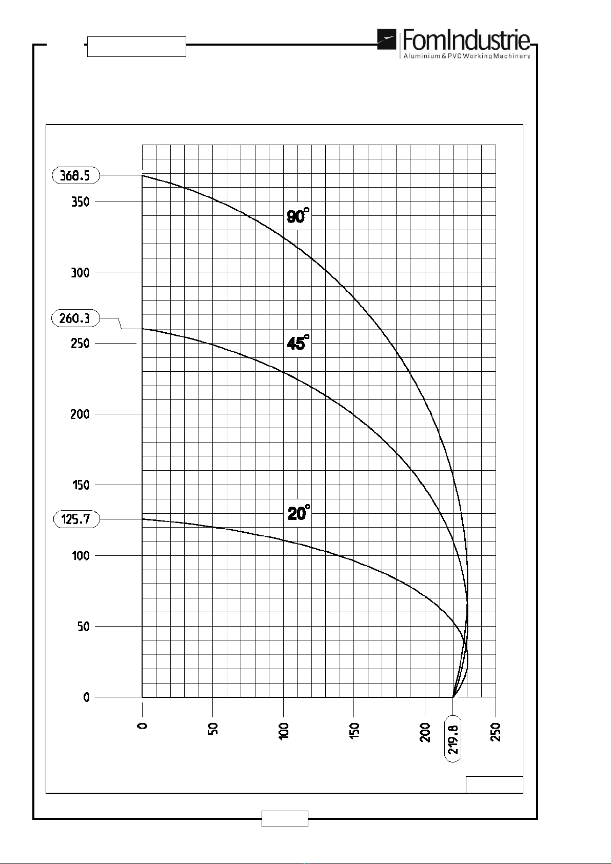
Cutting diagram - BLITZ 60L (FIG. 03-04)
Thecutting diagram with the blade Ø 600 mm. illustrates the machine cutting capacity with the blade set
at90°,
with the blade set at 45° internal/external and with the disc set at 20° external.

11
BLITZ G BG B
G BG B
G B
3.2 TECHNICALSPECIFICATIONS
- Tungsten carbide sawblades Ø 500 mm. (BLITZ 50) - Ø 550 mm. (BLITZ 55) - Ø 600 mm. (BLITZ 60L)
- Hydraulically operated tungsten carbide sawblade feed (adjustable exit speed – quick return)
- Three-phase motors 2.2 kw 2800 r.p.m. - 400V 50Hz
- Direct motor – saw blade transmission
- Sawblade rotation speed: 2800 rpm.
- Blade holding spindle Ø 32 mm.
- Heads tilted by electronic control:
BLITZ 50 : from 45° internal to 10° external
BLITZ 55 : from 45° internal to 12° external
BLITZ 60L : from 45° internal to 20° external
with all intermediate angles electronically programmed
- First head: fixed
- Second head: mobile (automatic positioning)
- Mobile head positioning speed (in automatic mode): <= 25 m/min
- Minimum cutting capacity between the two heads (See Section 9.4)
- Software for undersize cutting
- Max. cutting capacity between the two heads (at 90°): 5000-6600 (depending on the version supplied)
- Double working pressure servo-controlled in low pressure
- Air consumption per work cycle: 53 Nl (normal/litres)
- Total power absorption: 5.9 Kw at 400 V AC
- Total absorbed current: 10 A at 400 V AC
- Electrical switchboard separate from pneumatic one
- Pneumatichorizontal vices(4)andverticalvices(2) withautomaticexclusionbyprogramfor internallyangled
cuts from 70° to 45°
- Microdrop cutting lubrication with pure oil
- Set up to take chips and fumes extraction system (1)
- Working pressure: 7 bar (adjustable)
- Mobile head roller table (2,5 m)
- Integral protective hood around cutting area
- Control console with PC (only on version E)
Upon request:
- Manual kit for undersize cutting
- Mechanical stop for wedge cutting
- Blade rotation inverter kit
- Profile clamping
- Fixed head 3/4.2 m roller table
- Retractable pneumatic middle profile supports
- Retractable external profile support kit
- Profile raising middle roller kit (on mobile head)
- Central swarf conveyor belt
- Kit for conveying chips to centre of machine
- Angled conveyor belt
- Profile height reader + vertical vice (on loading side head)
- External supplementary vertical vice kit
- Remote assistance
- Label printer
- ‘Step-by-step’ cutting program with bi-manual control
- ‘Step-by-step’ cutting program with photocell safety barrier
(1) The exhauster must be installed by the customer under his own responsibility.
12
G BG B
G BG B
G B BLITZ
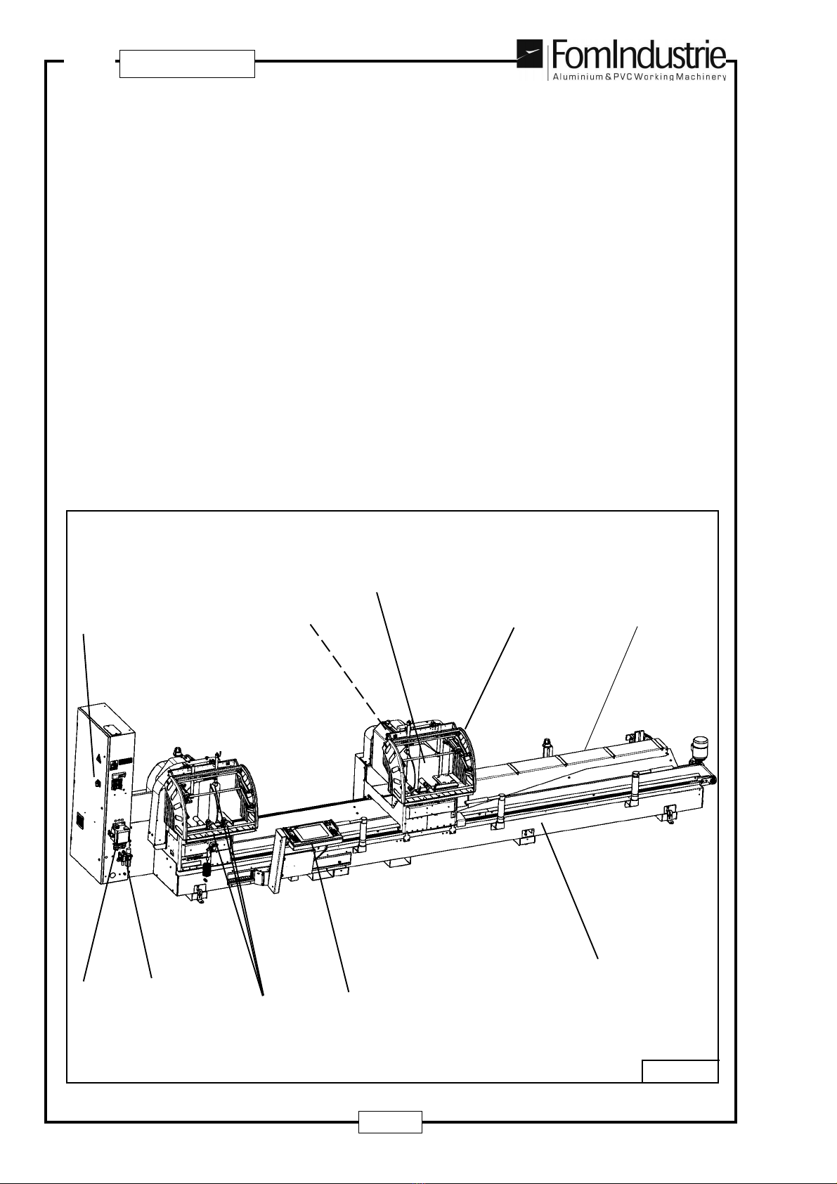
3.3 BASIC MACHINE VERSION COMPONENTS (Fig. 03-03)
1 - Machine bed complete with linear guides
2 - Heads complete with motors, blades and recirculating ball screws for head tilting
3 - Integral guard kit for cutting zone
4 - Pneumatic vices
5 - Sliding console with control panel and PC (only on version E)
6 - Electrical cabinet
7 - Pneumatic circuit at rear of fixed head and mobile head
8 - Air input filter
9 - Microdrop lubrication system
10 - Mobile head roller table
03-03
4
9
7
5
3
1
8
2
10
6

13
BLITZ G BG B
G BG B
G B
3.4 SOUND EMISSION OF THE BLITZ SAWING MACHINE
NOISE VALUES ACCORDING TO ISO 3746/77
Lwa Sound power level dB (A) : 109.1
LpA Sound pressure level at workstation dB (A) : 90.6
N.B: For prolonged machine use personal safety protection against noise is advised.
The sound pressure level has been calculated on the basis of a machining cycle involving the 2 blades cutting
Ø 550 mm. at 90° a 1.5 m length of 80x40 mm and 2 mm thick aluminium profile.
14
G BG B
G BG B
G B BLITZ
4 HEALTH AND SAFETY STANDARDS
4.1 FOREWORD
Each machine operator should have a perfect knowledge of the location and working operation of all controls
as well as the machine characteristics. It is therefore essential that they read this manual fully. Furthermore,
the instruction manual must be kept near the machine.
Unauthorised tampering or replacement of machine parts, the use of accessories, tools and consumable
materialsotherthanthoserecommendedbytheManufacturercanleadtoaccidentsforwhichtheManufacturer
declines responsibility for all penal or civil liabilities.
4.2 INTENDED MACHINE USE
The BLITZ sawing machine has been designed for cutting profiles in aluminium or light alloy.
Any materials other than these are not compatible with the specific machine characteristics.
WARNING
The machine is not suitable for use in environments where there is the risk of fire or explosion.
All combustible and/or flammable materials should be kept as far away from the machine as possible.
The machine has been specifically designed to be used by a single operator.
4.3 SAFETY WARNINGS
The term “OPERATOR” specifically refers to the person or persons entrusted with installing, operating,
adjusting,carryingout maintenance,cleaning,repairingandhandlingthe machine; “DANGEROUSAREAS”
refers to any area inside and/or near the machine in which the presence of an exposed individual constitutes
a risk to the health and safety of that person; “EXPOSED INDIVIDUAL” refers to any person standing fully
or partially in a dangerous area.
Working conditions
- According to the provisions of “lighting in work areas”, the place where the machine is used must have no
areasinshadow,glaringlights(reflections-reverberation),ordangerousstrobeeffectscausedbythelighting
in the workshop. The selected area must be well lit (minimum 300 lux).
- Furthermore, efficient ventilation must be guaranteed in the workplace with the use of a suitable extraction
system where necessary.
- The areas where the operator works should always be kept clear and clean from any oil residue.
Intended machine use
- The machine must be operated by skilled staff only and is designed for machining "NON-TOXIC” “NON
AGGRESSIVE”and“NONEXPLOSIVE”materials; theuse of any products otherthantheseabsolvesthe
Manufacturer from any responsibility for damage caused to the machine, persons or property.
- The machine can work at ambient temperatures from 10° to +40°. During storage periods or when the
machine is not working, the ambient temperature must be between -10° and + 60°.
- Before setting to work, the operator must have a perfect knowledge of the location and working operations
of all controls as well as the machine characteristics.
- The machining commands must be given by just one operator; the assistance of more than one operator
is only allowed in the workpiece loading phase.
This manual suits for next models
3
Table of contents
Languages:
Other FOM INDUSTRIE Saw manuals


