Fona CDRelite B2272100 User manual
FONA CDRelite Sensor and
USB Interface User Guide
B1057003
Sirona Dental, Inc.
30-30 47th Avenue, Suite 500
Long Island City, NY 11101
USA
(718) 937-5765
(718) 937-5962 (fax)
Sirona Dental GmbH
Fabrikstr. 31
D-64625, Bensheim
Germany
PART NUMBER B1057003 REV. 3

Copyright 2017 by Sirona Dental, Inc.
All Rights Reserved
August 7, 2017
Printed in the United States of America
This document was originally prepared in English
Sirona Dental, Inc. products are covered by one or more US patents.
For a current listing, please refer to the following page on our website:
http://www.schickbysirona.com/items.php?itemid=13112

FONA CDRelite System User Guide B1057003 Rev. 3
i
Contents
1. Overview........................................................................................1
1.1. Purpose......................................................................................................................................1
1.2. Indications for Use....................................................................................................................1
1.3. System Description ...................................................................................................................1
1.4. Replaceable Cable.....................................................................................................................2
1.5. PC Workstation Description......................................................................................................2
1.6. Relationship with Current FONA Sensors................................................................................4
2. Hardware........................................................................................5
2.1. Connecting Cables to the FONA CDRelite USB Interface Module .........................................5
2.2. Installing the FONA CDRelite USB Interface Module Holder.................................................6
3. Software.........................................................................................8
3.1. What You Will Need to Complete this Section ........................................................................8
3.2. Before You Start Installing Software........................................................................................8
3.3. Setup with Windows Vista........................................................................................................9
3.4. Sensor Calibration File Installation.........................................................................................11
3.5. Image Enhancement................................................................................................................11
3.6. CDR AutoDetect.....................................................................................................................15
3.7. Using the CDR Elite Utility ....................................................................................................17
4. LED Indicators............................................................................22
4.1. FONA CDRelite USB Interface Module Indications..............................................................22
5. Operation.....................................................................................23
5.1. Operating the System..............................................................................................................23
5.2. Using Your FONA CDRelite Sensor ......................................................................................24
5.3. Acquiring X-ray Images with Keyboard Shortcuts.................................................................29
6. Protective Measures..................................................................30
6.1. Introduction.............................................................................................................................30
6.2. Cleaning and Disinfecting.......................................................................................................30
6.3. Recommended Disinfectants...................................................................................................31
7. Maintenance................................................................................32
7.1. Visual Inspection.....................................................................................................................32
7.2. Damaged Sensor......................................................................................................................32
7.3. Periodic Maintenance..............................................................................................................32
8. Cable Replacement....................................................................33
Appendix A. Reference.................................................................40
A-1. Removal and Replacement......................................................................................................40
A-2. Part Numbers...........................................................................................................................40
A-3. Summary of Specifications .....................................................................................................41
A-4. Leakage Current Statement.....................................................................................................42

B1057003 Rev. 3 FONA CDRelite System User Guide
ii
A-5. EMC Tables ............................................................................................................................43
Appendix B. Troubleshooting Tips............................................46
B-1. Introduction.............................................................................................................................46
B-2. Troubleshooting Table ............................................................................................................46
List of Figures
Figure 1. FONA CDRelite USB Interface Module Cable Connections .............................................5
Figure 2. FONA CDRelite USB Interface Module Holder.................................................................6
Figure 3. Enhancements: Smooth (top) and Edge High (bottom) ....................................................13
Figure 4. Enhancements: Edge Low (top) and None Applied (bottom)...........................................14
Figure 5. FONA CDRelite USB Interface Module LED and Connector Views ..............................22
List of Tables
Table 1. Description of FONA CDRelite USB Interface Module Cable Connections.......................5
Table 2. FONA CDRelite USB Interface Module LED Indications.................................................22
Table 3. Proper Sensor Removal from Protective Sheath.................................................................25
Table 4. Examples of FONA CDRelite Sensor-to-Image Orientation..............................................26
Table 5. Keyboard Shortcuts ............................................................................................................29
Table 6. Orderable Item Part Numbers.............................................................................................40
Table 7. Specifications......................................................................................................................41
Table 8. Guidance and Manufacturer's Declaration - Electromagnetic Emissions...........................43
Table 9. Guidance and Manufacturer's Declaration - Electromagnetic Immunity ...........................43
Table 10. Recommended Separation Distance Between Portable and Mobile RF Communications
Equipment and the FONA CDRelite USB Interface Module............................................45

FONA CDRelite System User Guide B1057003 Rev. 3
iii
Safety Issues
Check FONA CDRelite Sensor and USB Interface Module before Using Them
Before each usage, check the outer surface of the FONA CDRelite
Sensor and USB Interface Module for any signs of physical damage
or defect. FONA CDRelite Sensor and USB Interface Module
surfaces should have a smooth finish, with no evidence of chipping
or damage. If detected, contact your local distributor.
To help ensure proper hygiene and to protect against infectious
disease, refer to Section 6, Protective Measures, and observe all
device cleaning and patient protection recommendations specified
there.
Do Not Touch Exposed Connectors on Non-Medical Equipment and the
Patient at the Same Time
When the FONA CDRelite Sensor and USB Interface Module are in
use, avoid touching exposed connectors on non-medical electrical
equipment and the patient at the same time. The human body is
capable of conducting electrical current and may cause a shock
hazard to patients if appropriate safety practices are not observed.
Follow All Instructions to Ensure Cable Replacement Procedures are
Performed Correctly
Follow all instructions to ensure the successful replacement of your
FONA CDRelite cables. When performing the cable replacement
procedure, it is especially important to tighten the screws that attach
the cable to the Sensor by turning them at least one-quarter
revolution clockwise after initial resistance or until they cannot be
turned any further. An improperly attached cable may cause an
intermittent connection and prevent the Sensor from operating
effectively. Refer to Section 8, Cable Replacement, for complete
instructions.
Use Only USB Cables Approved for the FONA CDRelite System
For normal operation of your FONA CDRelite system and to ensure
compliance with regulatory EMC and EMI standards, use only the
USB cables described and specified for your system. Refer to
Section 2.1, Connecting Cables to the FONA CDRelite USB
Interface, for details. EMC and EMI information may be found in
the appendix, Section A-5, EMC Tables.

B1057003 Rev. 3 FONA CDRelite System User Guide
iv
Do Not Connect Items that are Not Part of the System
Only items specified for use with the FONA CDRelite Sensor and
USB Interface Module are to be connected to it. The device should
not be used adjacent to other equipment that is not part of the
system. If, however, use with adjacent equipment is necessary,
normal operation should be observed and verified in that
configuration.
RF Interference Considerations
Although the FONA CDRelite Sensor and USB Interface Module
are designed to provide a reasonable degree of protection from
electromagnetic interference, according to IEC International
regulations, they must be installed at an adequate distance from
electricity transformer rooms, static continuity units, two-way
amateur radios and cellular phones. To ensure proper operation, the
latter (meaning, electricity transformer rooms, static continuity
units, two-way amateur radios and cellular phones) can be used only
at a minimum distance of 5 feet (1.5m) from any part of the FONA
CDRelite Sensor and Interface Module.
Any instrumentation or equipment for professional use located near
the FONA CDRelite Sensor and USB Interface Module must
conform to Electromagnetic Compatibility regulations, to which the
EMC tables in this document’s Appendix serve as guidance. Non-
conforming equipment, with known poor immunity to
electromagnetic fields, may not operate properly unless they are
installed at a distance of at least 10 feet (3m) and supplied by a
dedicated electrical line.
Installers to Ensure that FONA CDRelite Sensor and USB Interface Module
Operate Optimally
Installers must ensure that the FONA CDRelite Sensor and USB
Interface Module provides the user with the optimal use of the
equipment. This includes, but is not limited to, ensuring that the
system operates as described in this document. Installers must also
ensure that the system presents no physical obstacles or hazards
during operation and when not in use. To verify this requirement,
installers shall confirm that the FONA CDRelite Sensor and USB
Interface Module are installed as described in this User Guide and
shall perform the appropriate procedures therein.
Only Dentists or Authorized Designees Are Permitted to Operate the System
To ensure the correct use of the FONA CDRelite Sensor and USB
Interface Module in a clinical environment, for purposes that
correspond to its intended design and application, only dentists, or
their designees, are authorized to operate the system.

FONA CDRelite System User Guide B1057003 Rev. 3
v
Ensure Proper System and PC Workstation Installation and Operation
The FONA CDRelite Sensor and USB Interface Module have been
determined to be in accordance with international safety standards
and are deemed suitable for use within the patient area, which
extends from the patient for a distance of 5 ft (1.5m). To comply
with these standards, do not operate non-medical equipment (such as
a PC workstation) inside the patient area. Outside the patient area,
the presence of approved non-medical grade equipment and Listed /
Approved / IEC 60950-1 certified Information Technology
Equipment (ITE) computer equipment is acceptable.
The host computer (PC workstation) should be CE-approved and
conform with the Low Voltage [73/23/EC] and EMC Directive
[89/336/ERC]. Also, to help ensure optimal performance, ensure
that all software programs residing on the workstation are virus-free
and have been adequately tested so they will not impact imaging
applications after installation.
Operate the FONA CDRelite Sensor and USB Interface Module as Directed
Always use the FONA CDRelite Sensor and USB Interface Module
in accordance with the directions and recommendations contained in
this User Guide. Do not attempt to modify the FONA CDRelite
Sensor and USB Interface Module or use it in system configurations
not specified in this document.
Protect Sensor from Potential ESD Damage
Like other electronic devices, your FONA CDRelite Sensor is
susceptible to electrostatic discharge (ESD), particularly when the
device is used in or around carpeted areas or low-humidity
environments. During cable replacement, when Sensor contacts are
exposed, it is especially important to protect the device from
potential ESD damage. Touching a metal surface prior to replacing
the FONA CDRelite cable will reduce the risk of damaging Sensor
components by accidental static discharge. The use of anti-static
floor mats or floor treatments (for example Staticide 2005/2002) will
also help eliminate static build-up in your office.
Wait for Appropriate Prompts before Operating X-ray Source
To avoid exposing the patient to unnecessary X-rays, ensure that the
CDR exam window viewbox is flashing green (default color) in
AutoTake mode, or that the message, “Waiting to take X-ray,” is
displayed before triggering the X-ray Source.

B1057003 Rev. 3 FONA CDRelite System User Guide
vi
Always Use Sheaths with Sensors
Use approved sheaths every time the Sensor is used. Never use the
Sensor without a protective sheath. Never use a damaged sheath.
Always dispose of the sheath after every patient.
Protective sheaths are single-use devices and must not be reused
under any circumstance. Reuse of single-use devices/instruments
may cause them to become contaminated, compromise their
intended function, and result in patient and user infection, injury
and/or illness.

FONA CDRelite System User Guide B1057003 Rev. 3
vii
Explanation of Symbols
Sirona Dental products display a number of markings which indicate
compliance with regulatory requirements or which provide
information in accordance with applicable technical standards.
The symbols and their descriptions are provided below.
Symbol
Description
Indicates Class II equipment in accordance with applicable medical
device safety standards (IEC/EN/UL 60601-1)
Indicates Type BF equipment in accordance with applicable medical
device safety standards (IEC/EN/UL 60601-1)
Indicates an attention to users to consult accompanying documents (this
User Guide) for more information
Indicates that in the European Union, at the end of product life this device
must be disposed of in accordance with the requirements of the Waste
Electrical and Electronic Equipment (WEEE) directive 2002/96/EC
Indicates that this product meets North American safety standards. The
ETL mark is a Nationally Recognized Testing Lab (NRTL) marking and
indicates conformance with UL 60601-1 and CAN/CSA STD C22.2 NO
601.1-M90
Indicates that the product has been tested and evaluated to meet the
electrical safety requirements, according to IEC 60601-1, for electronic
products sold within Brazil
Indicates that this product conforms to European Union Medical Devices
Directive (MDD) 93/42/EEC
Indicates that this product does not contain toxic and hazardous
substances or elements above the maximum concentration values, and
that it is an environmentally-friendly product which can be recycled and
reused
Label Location
This label can be found on the FONA CDRelite Interface Module.

B1057003 Rev. 3 FONA CDRelite System User Guide
viii
Waste Electrical and Electronic Equipment
Background
The European Union’s Waste Electrical and Electronic Equipment
(WEEE) Directive (2002/96/EC) has been implemented in member
states as of August 13, 2005. This directive, which seeks to reduce
the waste of electrical and electronic equipment through re-use,
recycling, and recovery, imposes several requirements on producers.
Sirona Dental and its Dealers are committed to complying with the
Directive.
WEEE Marking
All Sirona Dentalproducts subject to the WEEE Directive and
shipped after August 13, 2005 will be compliant with the WEEE
marking requirements. These products will be identified with the
“crossed-out wheeled bin” WEEE symbol shown below, as defined
in European Standard EN 50419, and in accordance with WEEE
Directive 2002/96/EC.
This “crossed-out wheeled bin” symbol on the product or its
packaging indicates that this product must not be disposed of with
other unsorted municipal waste. Instead, it is the user’s
responsibility to dispose of Electrical and Electronic Equipment
(EEE) by handing it over to a designated collection point for the
reuse or recycling of waste electrical and electronic equipment. The
separate collection and reuse or recycling of Electrical and
Electronic waste equipment will help to conserve natural resources
and ensure that it is recycled in a manner that protects the
environment and human health. For more information about where
you can drop off your waste equipment for recycling, please contact
your local officials.
Reporting
According to the WEEE Directive, Sirona Dental or its Dealers will
ensure that information needed to calculate the financial obligations
with respect to EEE products will be provided as required.

FONA CDRelite System User Guide B1057003 Rev. 3
ix
WEEE from Users other than Private Households
According to the WEEE Directive, Sirona Dental or its Dealers will
fulfill its obligations for the management of WEEE from users other
than private households.
Furthermore, as required by the WEEE Directive, in order to
determine unequivocally when the equipment was put on the
market, the maufacturer’s date is placed on the equipment.
Information for Reuse Centers, Treatment and Recycling Facilities
As required by the WEEE Directive, Sirona Dental or its Dealers
will provide reuse, treatment, and recycling information for each
type of new EEE put on the market within one year of the date in
which the equipment is put on the market.
Information will include the different EEE components and
materials as well as the location of substances in these items. The
information will be provided as a printed document or in electronic
media (on CD-ROM or by web download, for example).
B1057003 Rev. 3 FONA CDRelite System User Guide
x
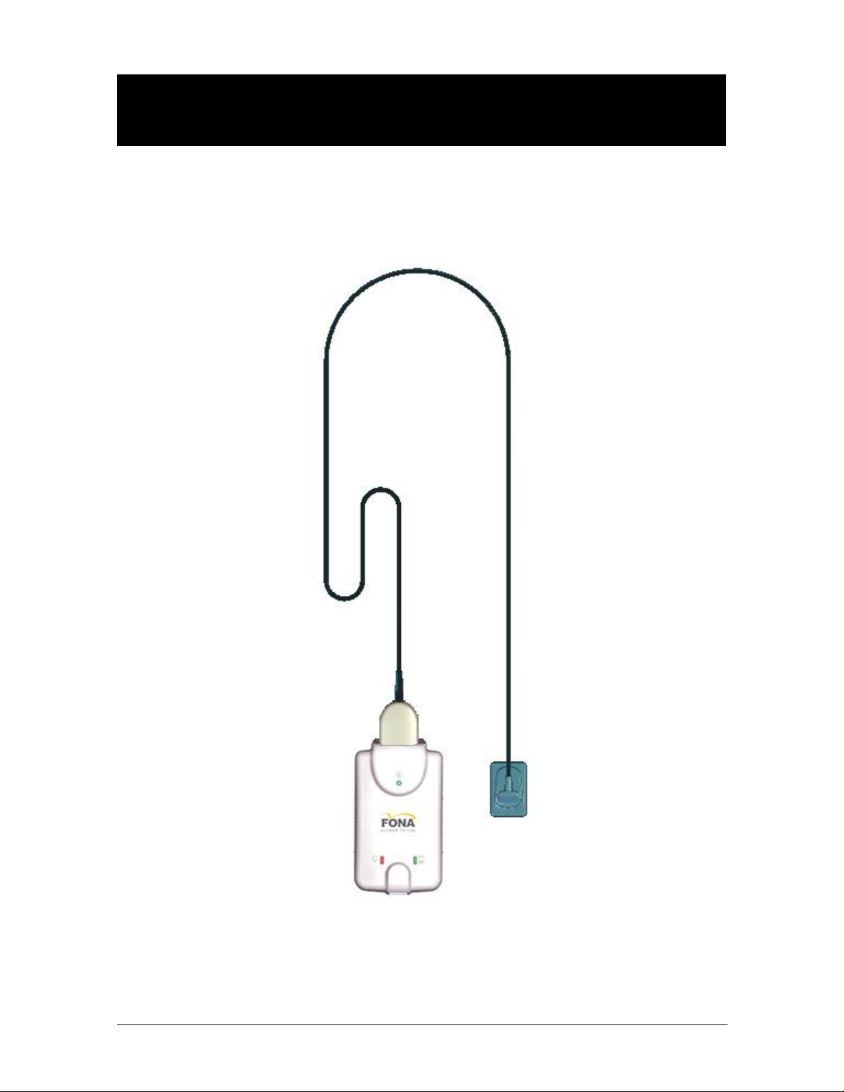
FONA CDRelite Sensor and USB Interface
Module
FONA CDRelite Sensor with FONA CDRelite USB Interface Module

FONA CDRelite System User Guide B1057003 Rev. 3
1
1.Overview
1.1. Purpose
The FONA CDRelite Sensor and FONA CDRelite USB Interface
Module represent the latest advances in our intraoral sensor
technology and provides the following advantages:
Improved image resolution based on smaller pixel size
Sensor calibration disks no longer required
Greater resistance to kinking for improved cable flexibility
Improved resistance to interference from other electronic
devices
Serviceable Sensor cable is standard with all FONA CDRelite
Sensors
New options for image enhancement.
1.2. Indications for Use
The FONA CDRelite Sensor is to be used as part of an intraoral
image acquisition system and is indicated for individuals requiring
intraoral dental examinations.
1.3. System Description
The FONA CDRelite Sensor is connected to the FONA CDRelite
Interface Module, which is connected via a USB A-B cable
(supplied separately) to a compatible PC workstation. The
workstation runs a compatible Windows operating system and also
provides the power source for the device. Additional details on the
PC workstation may be found in Section 1.5. Additional details on
the USB cable may be found in Section 2.1.
Support for the FONA CDRelite Sensor is provided by compatible
software programs such as FONA OrisWin. Section 1.5 lists the
operating systems compatible with the FONA CDRelite system.
The FONA CDRelite Sensor includes a detachable holder so the
device can be mounted either by screws to a wall or to another stable
surface. Details on installing the FONA CDRelite USB Interface
Module holder may be found in Section 2.2.

B1057003 Rev. 3 FONA CDRelite System User Guide
2
1.4. Replaceable Cable
The FONA CDRelite Sensor Imaging System is designed to meet
the practical, timely needs of dental professionals. For this reason,
FONA CDRelite Sensor sizes 1 and 2 support a replaceable-cable
design that enables customers to make immediate, in-office
replacements of failed cables. Manufactured for safe and reliable
operation, the replaceable cable provides appropriate strain relief,
molded protection from electronic contacts and components, and
easy installation. Details on replacing FONA CDRelite cables may
be found in Section 8.
1.5. PC Workstation Description
The PC workstation connects to the FONA CDRelite USB Interface
Module via USB cable (supplied seperately) and serves as the host
for CDR DICOM or other compatible imaging software products.
The workstation provides the capability to display, manipulate,
store, and print images acquired from FONA CDRelite Sensors.

FONA CDRelite System User Guide B1057003 Rev. 3
3
Getting the best results from your FONA CDRelite system begins
with having a computer system suitable for capturing and displaying
intraoral images. For optimum performance, we recommend the
following:
1.5.1. Client or Standalone
Windows 7 and Windows 7 x64, Windows Vista SP2,
and Vista x64
Intel i7 or equivalent
4 GB RAM
256 MB graphics card
500 GB hard drive (practice-specific, depends on number of
patients)
Intel USB 2.0 or 3.0.
1.5.2. Server
Windows Server 2003 R2 (SP1 minimum) and Windows Server
2008 R2
TCP/IP networking protocols (for DICOM Servers)
4 GB RAM (recommended)
1 TB (recommended).
NOTE: To achieve maximum image transfer-to-display time, we
recommend quad-core processors, 8 GB RAM, Windows 7
operating system, and 512 MB graphics card. Recommended
minimum display resolution is 1280x1024.

B1057003 Rev. 3 FONA CDRelite System User Guide
4
1.6. Relationship with Current FONA CDRelite Sensors
If your current workstation supports FONA CDRelite Sensors, it
will also support FONA CDRelite Sensors. If both FONA CDRelite
and FONA CDRelite Sensors are connected to the same
workstation, they are detected automatically (by CDR AutoDetect,
as described in Section 3.6), and you can work with either Sensor
type.
The FONA CDRelite USB Interface Module that connects the
FONA CDRelite Sensor to the workstation via USB 2.0 cable is
unique to the FONA CDRelite Sensor type, however. This means
that you will not be able to swap FONA CDR Remote Modules with
FONA CDRelite Interface Modules. To avoid any possible
mismatch, the FONA CDRelite Module Interface enclosure is
specifically designed for the FONA CDRelite Sensor and the FONA
Stellaris Sensor and will not accommodate any other Sensor type for
which it was not intended.
FONA CDRelite System User Guide B1057003 Rev. 3
5
2.Hardware
2.1. Connecting Cables to the FONA CDRelite USB Interface
Module
IMPORTANT!DonotconnecttheFONACDReliteUSBInterfaceModuleandcableto
yourcomputeruntilafteryouhavesuccessfullyrunthesetupprogram. Proceduresfor
installingthesefilesaresuppliedinSection3,"Software."
The USB cable used with the device has a Series
"A" USB plug on one side and a Series "B" USB
plug on the other. The "A-type" plug connects to
any available USB port on the computer. The "B-
type" plug connects to the FONA CDRelite
Interface Module. cable part numbers and lengths are listed below:
B2250150 - 5 meters (16.5 feet)
B2250151 - 2 meters (6.5 feet)
B2250152 - 0.5 meter (1.6 feet)
IMPORTANT!FornormaloperationofyourFONACDRelitesystemandtoensure
compliancewithregulatoryEMCandEMIstandards,useonlytheUSBcablesdescribed
andspecifiedforyoursystem.
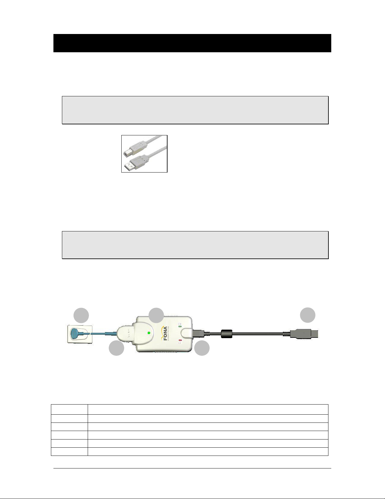
The FONA CDRelite Sensor and FONA CDRelite USB Interface
Module are shown in Figure 1. Cable connections are described in
Table 1.
Figure 1. FONA CDRelite USB Interface Module Cable Connections
Table 1. Descriptionof FONA CDRelite USB Interface Module Cable Connections
Number
Description
1
FONA CDRelite Sensor
2
FONA CDRelite Sensor cable connection
3
FONA CDRelite Interface Module
4
USB cable connection ("B" connector end of USB cable connects here)
5
USB cable connection ("A" connector end of USB cable connects to PC)
1
2
4
5
3
B1057003 Rev. 3 FONA CDRelite System User Guide
6
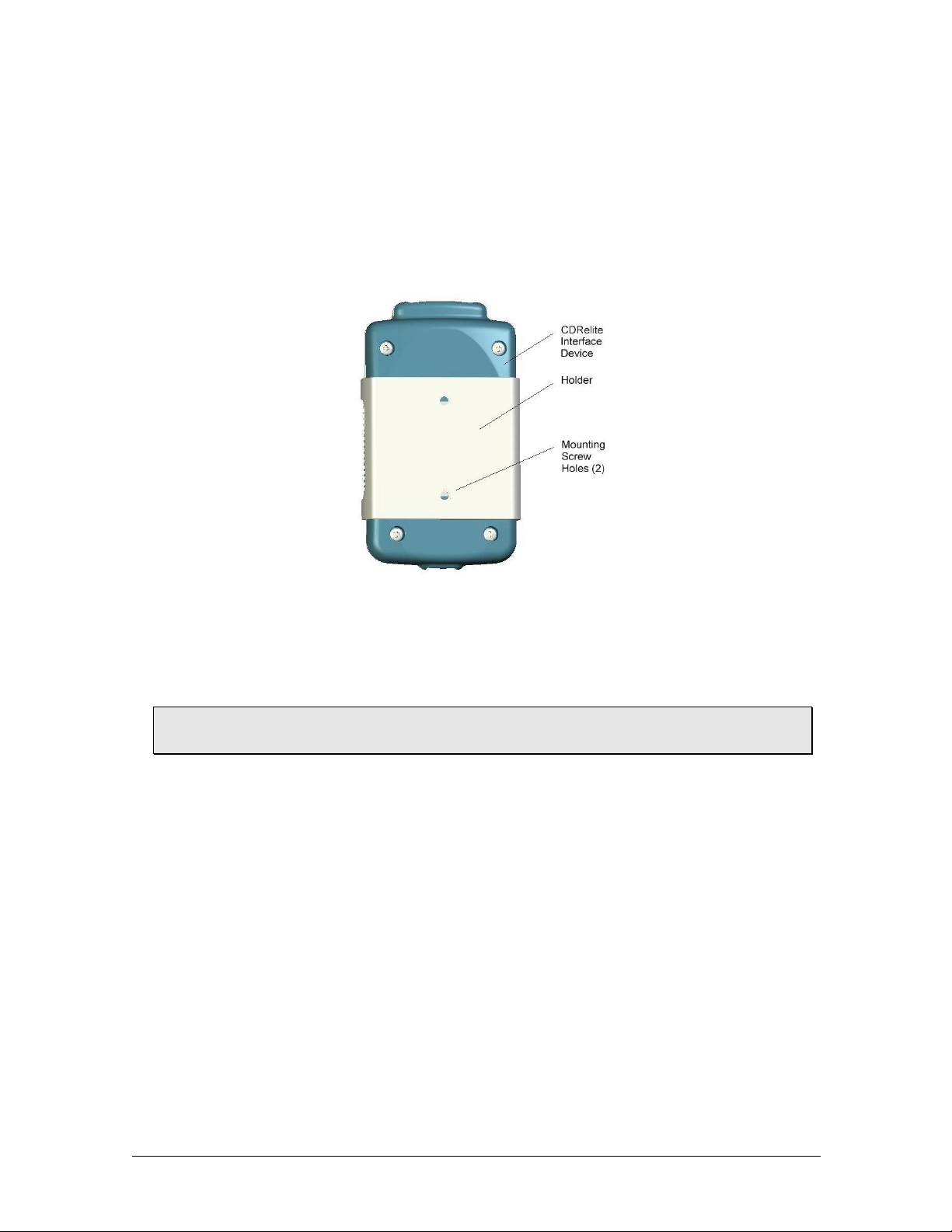
2.2. Installing the FONA CDRelite USB Interface Module
Holder
The FONA CDRelite USB Interface Module holder is designed for
several mounting options: (1) Wall-mounted with fastening
hardware, or (2) Attached to a wall or other acceptable bonding
surface with Velcro adhesive. When installing your FONA CDRelite
USB Interface Module choose a location that offers easy access and
visibility during patient exams.
Figure 2. FONA CDRelite USB Interface Module Holder
2.2.1. Wall-Mounting Option (with Fasteners)
IMPORTANT! Whenchoosingalocationfortheholder,makesuretherearenoelectrical
wiresorconnectionsthatcouldbecontactedaccidentallywhendrilling.
Install the holder by fastening it to a wall or other flat surface, as
follows:
1 . Remove the FONA CDRelite USB Interface Module from its
holder.
2 . Position the holder on a smooth stable flat surface. Using the
holes on the back of the holder as guides, fasten the holder
securely to the wall using 2 (#4) dry wall screws (supplied)
or other hardware appropriate to the mounting surface.
3 . Remove the FONA CDRelite USB Interface Module from its
holder

FONA CDRelite System User Guide B1057003 Rev. 3
7
2.2.2. Wall-Mounting Option (with Adhesive)
Install the FONA CDRelite USB Interface Module by attaching it
with Velcro adhesive to a wall or other flat surface, as follows:
1 . Remove the FONA CDRelite USB Interface Module from its
holder.
2 . Cut and trim a piece of Velcro adhesive (not supplied) to the
size of the back of the Remote. Remove one half of the tape
and attach it to the FONA CDRelite Interface Module
3 . Locate an accessible, stable, and flat surface for the module.
Apply the other half of the Velcro adhesive in that location
and attach the module securely.

B1057003 Rev. 3 FONA CDRelite System User Guide
8
3.Software
3.1. What You Will Need to Complete this Section
To expedite software installation, please have the following items
available:
FONA CDRelite Interface Driver CD
FONA CDRelite USB Interface Module
USB 2.0 A-B Cable (supplied separately)
3.2. Before You Start Installing Software
IMPORTANT!PleasedonotconnecttheFONACDReliteUSBInterfaceModuleand
USBcabletoyourcomputeruntilafteryouhaveinstalledthedevicedriver.Proceduresfor
installingthesefilescanbefoundonthefollowingpages.
The software component to accompany the your FONA CDRelite
USB Interface Module installation consists of the FONA CDRelite
USB Interface Module driver. You must install this driver
successfully to ensure proper operation of your FONA CDRelite
Interface Module.
Installation differs slightly among the Windows operating systems,
so you should follow the procedures that refer to your particular
system.
If you're not sure which operating system is installed on your
computer, right click on the My Computer icon on your desktop and
select Properties (pressing the Windows Start () and Break keys
will also display System Properties).
This manual suits for next models
3
Table of contents
Other Fona Dental Equipment manuals


