Fona XDG User manual
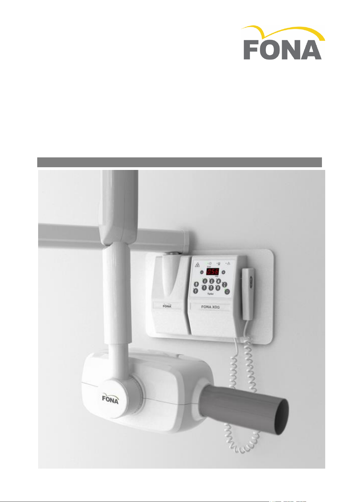
FONA XDG
Service and Installation Manual
English
FONA XDG –Service & Installation Manual
2/32 69 550 70210 150715
Table of Contents
FONA XDG Service and Installation Manual
English Edition
Version 150715 July 2015
Code 69 550 70210
Manufactured by FONA S.r.l.
Via Galilei 11 - 20090 Assago (MI) Italy
Distributed by FONA Dental s.r.o.
Stefanikova 7 SK-811 06 Bratislava, Slovakia www.fonadental.com
1. INTRODUCTION................................................ 4
1.1 PURPOSE........................................................ 4
1.2 EQUIPMENT CLASSIFICATION.............................. 4
1.3 APPLICABLE STANDARDS ................................... 4
1.4 ENVIRONMENTAL DATA .................................... 4
1.5 OBLIGATIONS OF THE INSTALLER ......................... 4
1.6 WARNING ...................................................... 4
1.7 DEMONSTRATION ............................................ 4
2. TECHNICAL DATA ............................................. 5
2.1 SYSTEM SUPPLY............................................... 5
2.2 X-RAY HEAD ASSEMBLIES .................................. 5
2.3 BEAM LIMITING DEVICE .................................... 5
2.4 TIPSET TIMER ................................................. 5
2.5 MECHANICAL SUSPENSION SYSTEM ..................... 5
2.6 WEIGHTS ....................................................... 5
3. ASSEMBLY AND INSTALLATION ........................ 6
3.1 WALL MOUNTED SYSTEMS ................................ 6
3.2 DIP SWITCH SETTING ...................................... 16
3.3 LAYOUT POWER BOARD TIMER......................... 17
3.4 MOBILE SYSTEMS .......................................... 18
3.5 MOUNTING THE TIMER ................................... 19
4. MAINTENANCE............................................... 20
4.1 MAINTENANCE OF WALL ADAPTOR................... 20
4.2 MAINTENANCE OF SUPPORT ARM..................... 20
4.3 MAINTENANCE OF SCISSOR ARM ...................... 21
4.4 MAINTENANCE OF X-RAY HEAD........................ 22
4.5 MAINTENANCE OF BEAM LIMITING DEVICE......... 22
4.6 MAINTENANCE OF TIMER................................ 22
4.7 CHECKING FILAMENT PRE-HEATING TIME .......... 22
4.8 SERVICE FUNCTIONS....................................... 23
5. MEASUREMENTS ............................................ 24
5.1 LINE VOLTAGE .............................................. 24
5.2 ANODE VOLTAGE –KVP................................. 24
5.3 ANODE CURRENT –MA .................................. 24
5.4 EXPOSURE TIME ............................................ 24
5.5 LEAKAGE RADIATION ...................................... 25
5.6 EARTH RESISTANCE-....................................... 25
5.7 EARTH LEAKAGE ............................................ 25
APPENDIX A SYSTEMS AND COMPONENTS ............ 26
APPENDIX B ICONS................................................. 27
APPENDIX C EXPOSURE TABLE ............................... 28
APPENDIX D ALARM CONDITIONS ......................... 29
APPENDIX E IDENTIFICATION LABELS ..................... 30
APPENDIX F COOLING CURVES ............................... 31
FONA XDG –Service & Installation Manual
150715 69 550 70210 3/32
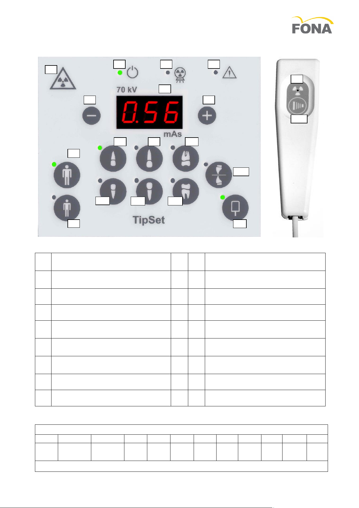
The Control Panel
1
Device for emission of ionizing
radiation on request
10
Maxillary incisor
2
Indication of system turned on and
ready
11
Maxillary canine or premolar
3
Irradiation
12
Maxillary molar
4
Alarm
13
Mandibular incisor
5
mAs display, the controlled
technique factor
14
Mandibular canine or premolar
6
Manual decrease of controlled
technique factor
15
Mandibular molar
7
Manual increase of controlled
technique factor
16
Bite-wing premolar
8
Patient size adult/large
17
Digital detector in use
9
Patient size child/small
18
Radiation exposure pushbutton
EXPOSURE INDEX
0.32
0.4
0.5
0.63
0.8
1.0
1.25
1.6
2.0
2.5
3.2
4.0
CDR
SENSOR
XIOS
SENSOR
F
FILM
E
FILM
D
FILM
CDR Sensor by Shick Technologies Inc., XIOS Sensor by Sirona Dental Systems GmbH
18
1
1
2
3
4
5
6
7
8
9
10
11
12
13
14
15
16
17
FONA XDG –Service & Installation Manual
4/32 69 550 70210 150715
1. INTRODUCTION
1.1 Purpose
The FONA XDG X-ray Equipment is designed to fulfil the needs for high resolution intra-oral radiography in
the general dental practice. The systems can be configured for wall, mobile solutions.
The Operator’s Manual and the Service and Installation Manuals supplied with the system are integral part
of the product. The original language of the Operator’s Manual is English.
1.2 Equipment Classification
IEC: FONA XDG is a Class I, type B equipment
FDA: FONA XDG is a Class II medical device equipment (21 CFR 872-1800).
1.3 Applicable Standards
The FONA XDG system configurations comply with the following standards.
IEC 601-1
General requirements for safety
IEC 601-1-2
Electromagnetic compatibility
IEC 601-1-3
General requirements for radiation protection in diagnostic X-ray equipment
IEC 601-2-7
Particular requirements for the safety of high voltage generators of diagnostic
X-ray generators
IEC 601-2-28
Particular requirements for the safety of X-ray source assemblies and X-ray
tube assemblies for medical diagnosis
21 CFR 1020.30
Diagnostic x-ray systems and their major components
21 CFR 1020.31
Radiographic equipment
93/42/EEC
European Directive concerning medical devices (1993)
1.4 Environmental Data
Applicable ranges of temperature, humidity, and atmospheric pressure are reported here below both for
operation and transport conditions.
Ambient
Transport & Storage
Temperature
from 10 to 40 °C
from –20 to +50 °C
Relative Humidity
from 30 to 75%
10 to 90%
Pressure
from 700 to 1060 hPa
from 500 to 1060 hPa
1.5 Obligations of the Installer
Obligations of the Installer are:
To make sure that the line voltage specified by the Manufacturer of the equipment is available
and within the specified range.
For safety reasons verify that a proper switch is available to disconnect from line voltage supply when
needed during installation.
Install and test the equipment with due diligence according to the installation instructions from the
Manufacturer.
To provide the Operating Instructions to the User.
1.6 Warning
Use the system only after proper assembly and installation as per manufacturer’s instructions.
X-ray equipment produce ionizing radiation that may be harmful if not properly controlled. It is therefore
recommended that the equipment be operated by trained personnel only in accordance with existing law.
Even if compliant to specifications of electromagnetic compatibility, it is recommended not to use the
equipment in presence of external electromagnetic fields, such as those generated by cellular phones,
which might interfere with the electronic circuits of the system.
1.7 Demonstration
In order to use of the system for demonstration purposes radiation emission has to be inhibited by
disconnecting the supply cables to the X-ray head into the wall adaptor or into the timer.
Cables to be disconnected are those leaving the connection block towards the X-ray head (“out”).
Make sure that the disconnected cables are properly insulated to prevent undesired contacts with live
points. This task has to be done by trained personnel only to avoid the risk of electrical shock.
FONA XDG –Service & Installation Manual
150715 69 550 70210 5/32
2. TECHNICAL DATA
2.1 System Supply
Line Voltage
110-120 V (from 99 V to 132 V in sub-ranges depending on THA mounted)
220-240 V (from 198 V to 264 V in sub-ranges depending on THA mounted)
Line Power
400 W
Line Voltage Range
108 - 132 V for type 93 256 01300, 207 - 253 V for type 93 256 01700,
216 - 264 V for type 93 256 01800
Line Fuse
Slow Blow: 6.3 A at 110-120 V, 4 A at 220-240 V, second fuse for 2 phases or cord
Line Frequency
50/60 Hz 1 Hz
Line Resistance
0.4 Ohm at 110-120 V, 0.8 Ohm at 220-240 V
Voltage regulation for max. line current: 2.1% at 110-120 V, 1.4% V at 220-240 V
2.2 X-ray Head Assemblies
Nominal Line Voltage
120 V for type 93 256 01300, 230 V for type 93 256 01700,
240 V for type 93 256 01800
Nominal Line Current
6 A at 120 V for type 93 256 01300, 4 A at 230 V for type 93 256 01700,
4 A at 240 V for type 93 256 01800
Anode Voltage
(peak tube potential)
70 kVp ± 8% at nominal line voltage
66 kVp ± 8% at nominal line voltage –10%
74 kVp ± 8% at nominal line voltage+ 10%
Anode Current
(tube current)
3.5 mA ± 10% at nominal line voltage
3.0 mA ± 10% at nominal line voltage –10%
4.0 mA ± 10% at nominal line voltage + 10%
Nominal Power
0.2 kW at 70 kVp, 3.5 mA, 0.1 s
X-ray Insert
CF4G070
Anode
Tungsten, angle 16° to the tube axis
Focal Spot
0.4 (EN 60336:1995-04)
Focal spot mark
Dot embossed on plastic covers of tube-head
Inherent Filtration
> 2.5 mm Al/70kVp (EN 60522: 1999)
Duty Cycle
1/15
Radiation Leakage
< 0.1 mGy/h a 1 m (< 11.5 mR/h a 1 m)
2.3 Beam Limiting Device
Beam Limiting
Device
Focus skin distance 21 cm (8.27”)
Circular radiation field 6 cm (2.35”) diameter /Rectangular 3.2x4.2 cm
(1.26”x1.65”)
Maximum 10% eccentricity
2.4 TipSet Timer
Supply Voltage
110-120 for type 93 354 60200, 220-240 for type 93 354 60100
Exposure factor
Time-current in mAs: from 0.21 to 11.2 mAs
0.21
0.28
0.35
0.42
0.56
0.70
0.88
1.12
1.40
1.75
2.20
2.80
3.50
4.40
5.60
7.00
8.75
11.2
Precision
± 0.04 mAs o 10% (whichever the greater) supplied at nominal line voltage
Exposure factors
Automatic setting through tooth type selection and patient build, for use with
traditional film or digital sensor, or manual setting with plus and minus keys.
Irradiation signal
Yellow light on hand-switch and on control panel plus acoustic buzzer
Hand-switch
Hand-switch with 3 m coiled cord, with remote mounting optional kit
Overall size
Width: 15 cm /6”, Height: 24 cm /9”½, Depth: 9 cm /3”½
2.5 Mechanical Suspension System
Wall Adaptor
12 cm /4.7” width, 24 cm /9.4” height, 9 cm /3.5” depth
Arm Length
Short (S): 30 cm /11.8”, Medium (M): 60 cm /23.6”,
Long (L): 80 cm /31.5”, Extra Long (XL) 100 cm /39,4”
Useful Reach
Arm S: 138 cm /54.3”, M: 168 cm /66.1”, L: 188 cm /74”, XL: 208 cm /81.9”
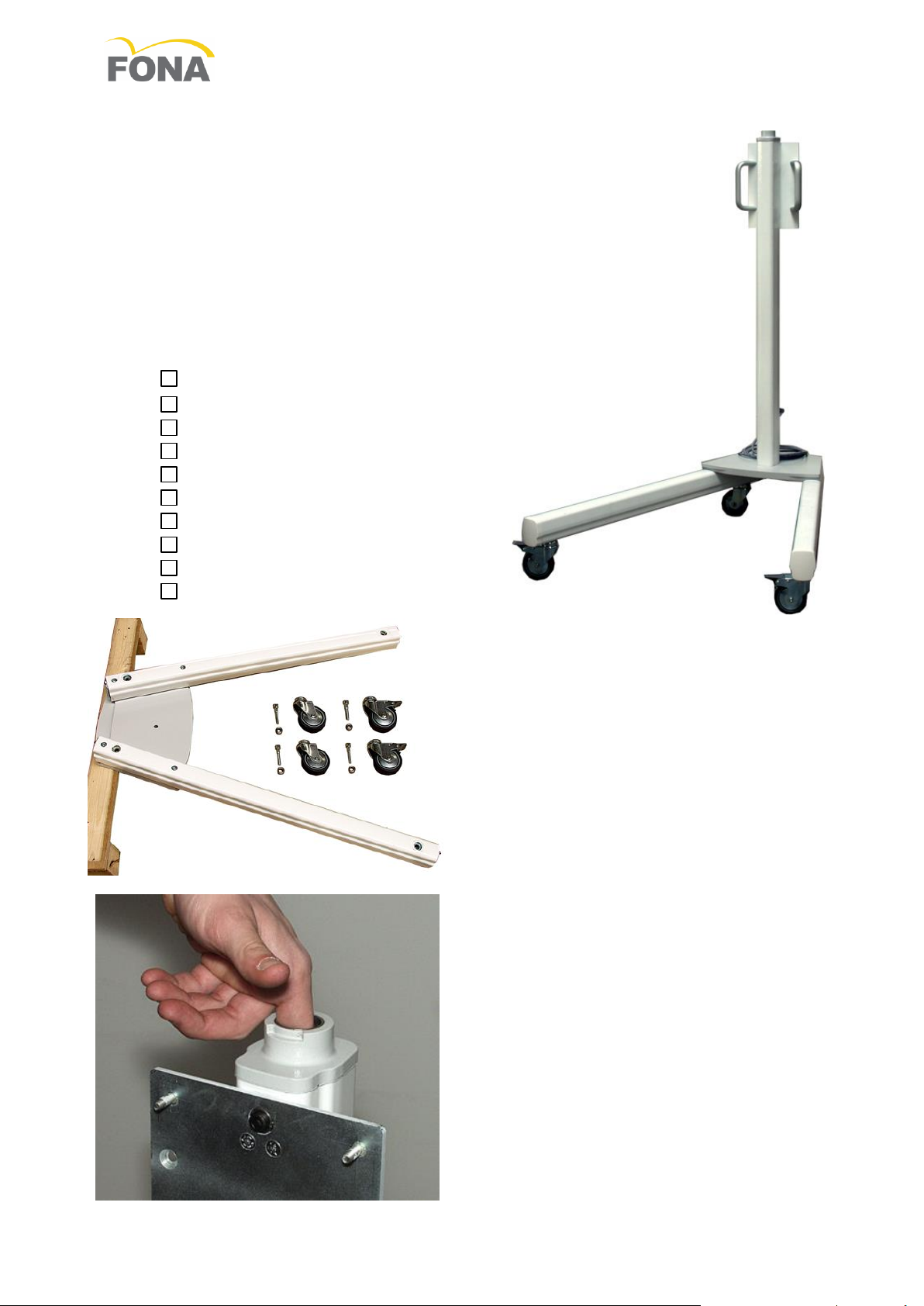
Mobile Stand
Size 78 x 92 cm (30” ¾ x 36” ¼), Height: 186 cm /73” ¼” with scissor arm
2.6 Weights
Timer
1.7 kg / 3.7 lb
Support Arm
Arm S: 2.8 kg /6.2 lb , M: 4.0 kg /8.8
lb, L: 4.8 kg /10.6 lb,
XL: 5.4 kg /11,9 lb
X-ray Head
6.6 kg / 14.5 lb
Circular BLD
0.1 kg / 0.22 lb
Rectangular BLD
0.2 kg / 0.44 lb
Wall Adaptor
1.3 kg / 2.9 lb
Scissor Arm
11.7 kg / 25.8 lb
Mobile Stand
29.4 kg / 64.8 lb
FONA XDG –Service & Installation Manual
6/32 69 550 70210 150715
T1
T2
T3
B1
B2
B3
3. ASSEMBLY AND INSTALLATION
3.1 Wall Mounted Systems
3.1.1 Installation Options
The timer box can be mounted together with the X-ray head on the right of the wall adaptor or can be
placed remote either inside or outside the examination room. The release hand-switch can be directly
connected to the timer box or placed remote making use of specific mounting kit including 10 m cable. A
door contact and/or a second exposure button can be added via the internal socket on the timer board.
3.1.2 Unpacking
Unpack the components of the system and check the following:
AEach item is in good conditions and was not damaged during
transportation.
BAll the items for the desired system configuration are available.
CThe line voltage on the labels of timer and X-ray head are
corresponding to the local line voltage.
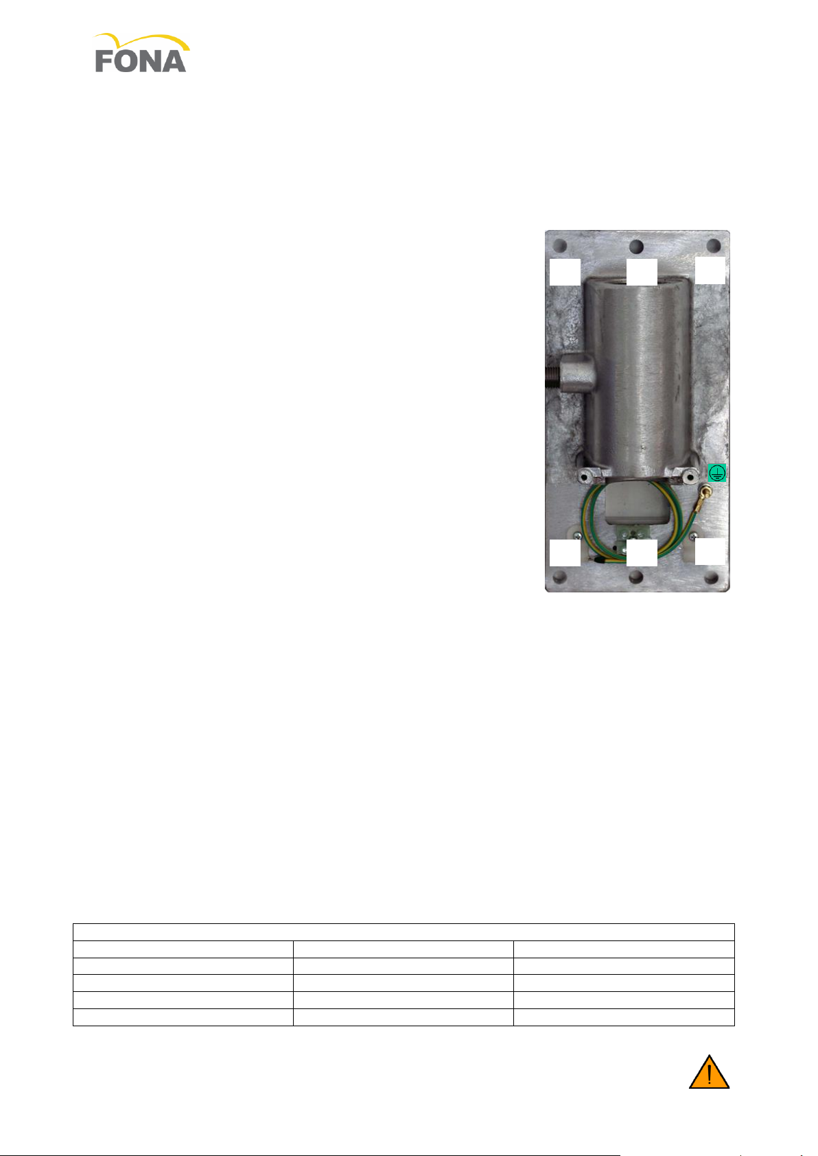
3.1.3 Structural Requirements
The wall adaptor has to be mounted in a convenient position on left or
right side of the chair or on back wall (head of the patient).
The maximum useful reach is of 208 cm (81.9”) from the wall when using
an 100 cm (39.4”) support arm.
The wall adaptor can be mounted with 2, 4, or 6 bolts, depending on wall
quality.
ATwo bolts only (top and bottom central holes –T2, B2) are used when
there is a solid slim column (e.g. iron mounting) with weak sides (e.g.
wooden wall). Considering the requested safety factor, the top bolt
has to withstand a load of 8878 N, comprehensive of a safety factor,
i.e. about 2013 lbs or 906 kg. Proper screw to be selected for a solid
connection to the wall. Classes ISO 8.8 (M 8, M 8x1, M 8x1.25) or SAE
Grade 5 (5/16” 18UNC, 5/16” 24 UNF) are recommended.
BFour bolts, two on top sides (T1, T3) and two on bottom sides (B1,
B3) is the regular mounting for solid (concrete) wall, but also on large metal plate. Considering the
requested safety factor, each bolt at top has to withstand a load of 4439 N, comprehensive of a safety
factor, i.e. about 1007 lbs or 453 kg.
Proper expansion screw to be selected for a solid connection to the concrete wall; the permissible load
of each screw has to be greater than 308 lbs (about 140 kg).
On solid concrete use heavy duty metal anchors.
On hollow bricks use injection chemical fixing.
CSix bolts, three on top (T1, T2, T3) and three at bottom (B1, B2, B3) are required when the wall is not
solid enough and the load has to be distributed on more points. Considering the requested safety
factor, each bolt at top has to withstand a load of 2959 N, comprehensive of a safety factor, i.e. about
671 lbs or 302 kg.
In case the wall is not in condition to withstand the indicated load, corrective actions can be evaluated by
adoption of reinforcing plates:
DLarge plate to fit vertical supports at 16” distance, with 4 mounting holes and one cable opening for
the wall mount in the middle.
EIn case of a thin (wooden) wall not solid enough, the use of a steel counter plate 2 mm thick can be
the solution. Make sure that the wall is solid enough to carry the load.
FThe use of two reinforcing steel plates of about 4 times the surface of the wall adaptor, one by each
side of the wall, can help when a single plate looks not adequate; additional bolts have to be used to
hold together the two plates.
Make sure that the wall is solid enough to carry the load.
Recommended Bolts
Diameter
Class
Core Section mm2
M 8X1.25
ISO 8.8
36.6
M 8X1
ISO 8.8
39.2
5/16” – 18 UNC
SAE- Grade 5
33.8
5/16 –24 UNF
SAE- Grade 5
37.41
INSUFFICIENT WALL OR HARDWARE STRENGHT MAY CAUSE THE WALL ADAPTOR TO
PULL OUT FROM THE WALL AND THE FULL SYSTEM TO FALL ON TO THE PATIENT OR
THE OPERATOR CAUSING INJURIES.
FONA XDG –Service & Installation Manual
150715 69 550 70210 7/32
INPUT
POWER
LINE
SWITCH
ELECTRONIC
TIMER
WALL
ADAPTOR
IN
OUT
X-RAY
HEAD
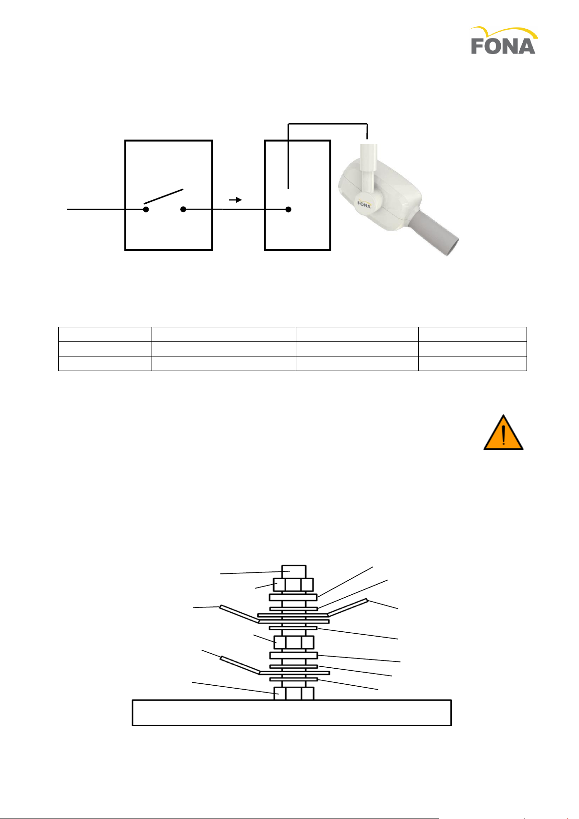
3.1.4 Electrical Requirements
The power line cable must be connected to the input terminals (IN) of the timer to supply the timer itself
and to make available power for the X-ray head at the output terminals (OUT), upon request by the
operator (via the hand switch). Power to the X-ray head is thus controlled by the timer (acting as a
SWITCH).
The cables (2 poles plus ground) to connect the power line to the timer and the timer to the wall adaptor
are not provided. Cables with large section conductors have minimum electrical resistance and voltage
drop.
Wire Type
Cross Section Area
Resistance/m
m/0.05 Ohm
AWG 14
2.08 mm2
0.00829 Ohm/m
6.0 m
AWG 12
3.31 mm2
0.00521 Ohm/m
9.6 m
The resistance between the ground provision in the connecting block of the timer and the metal body of
the tube housing assembly has not to exceed 0.1 Ohm. Proper section of the yellow green wire to be used
in case remote mounting of the timer.
The wall adaptor is provided with a common bolt for bonding and grounding blocked in place
with a nut which has not to be removed.
The grounding conductors to be connected as indicated below.
First the conductor to ground provision in the connecting block of the timer (flat washer, ground
provision, flat washer, lock-washer, nut).
Second the bonding conductor of support arm plus, in case, the one of the cable in the scissor arm
(flat washer, bonding conductors, flat washer, lock-washer, nut).
NUT
NUT
BLOCKING NUT DO
NOT REMOVE
FLAT WASHER
FLAT WASHER
LOCK-WASHER
GROUND PROVISION
TO TIMER
LOCK-WASHER
BONDING
CONDUCTOR OF
SUPPORT ARM
BONDING CONDUCTOR
OF SCISSOR ARM
(IN CASE)
COMMON BOLT
METAL BODY OF WALL SUPPORT
FLAT WASHER
FLAT WASHER
FONA XDG –Service & Installation Manual
8/32 69 550 70210 150715
3.1.5 Mounting and Connecting Sequence
Step 1
Mount the Wall Adaptor
Step 7
Connect the Hand-Switch
Step 2
Mount the Timer
Step 8
Optional Remote Hand-Switch
Step 3
Mount the Support Arm
Step 9
Mount and connect X-ray head
Step 4
Mount the Scissor Arm
Step 10
Mount the collimator
Step 5
Connect the Wall Adaptor
Step 11
Final Tuning and Set-Up
Step 6
Connect the Timer
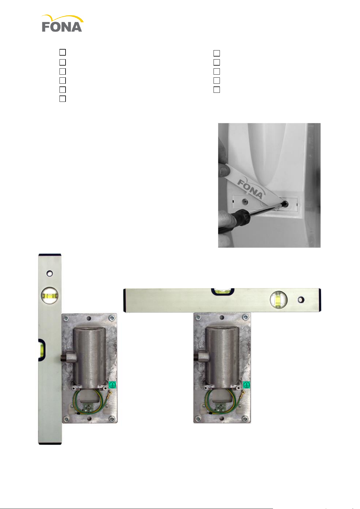
3.1.6 Mounting the Wall Adaptor
ATake away the plastic cover removing the screws under the
logo label.
BUse the Wall Adaptor plate or a template to mark the holes on
the wall.
Please note that the timer can be mounted close to the Wall
Adaptor on the right side or in a remote position. Cabling
should have been laid out accordingly.
CMake the holes in the wall according to the applicable type of
mounting with two, four bolts, or six bolts, with or without
reinforcing plate.
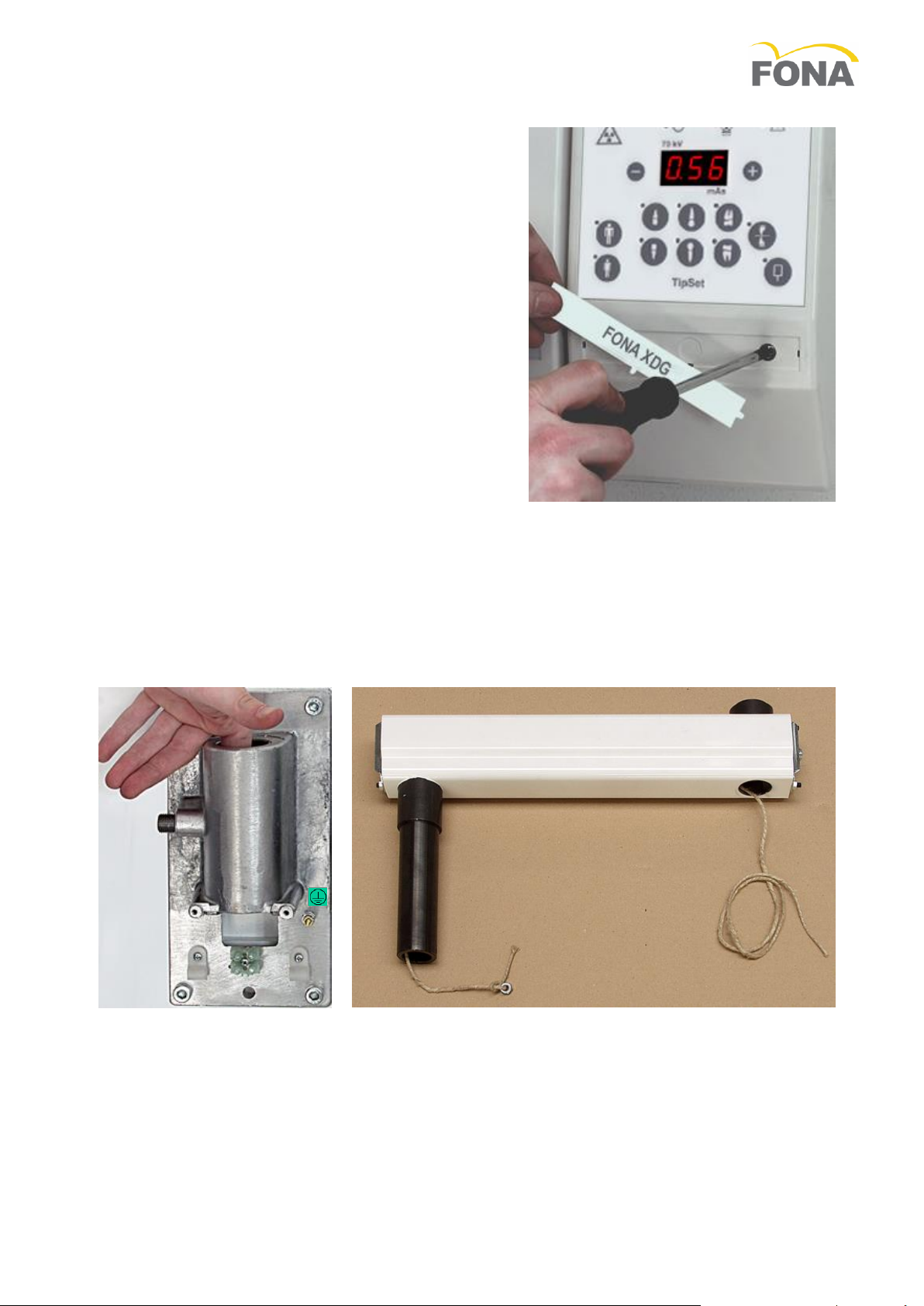
DSlide the logo-strip out from the plastic cover to access the
screws and remove it from the metal frame.
EMount the metal frame on the wall using proper heavy-duty
metal anchors and make sure that the power cable enters
from behind.
FSecure it to the wall ensuring it is leveled. Improper leveling
might cause the arm to move and swing out of position.
GPerform wire connection and final set-up complying with
recommended sequence of actions reported in the following.
FONA XDG –Service & Installation Manual
150715 69 550 70210 9/32
3.1.7 Mounting the Timer
AUse the mounting plate or the template to mark the
holes on the wall.
BRemove the plastic cover after having taken away the
blocking screws behind the logo strip. Pay attention
when disconnecting the flat cable of the control panel
from the control board.
CDrill the four holes in the wall and secure the timer
making sure it is leveled. Cabling should have been laid
out in accordance to mounting requirements.
DPerform wire connection and final set-up complying with
recommended sequence of actions reported in the
following.
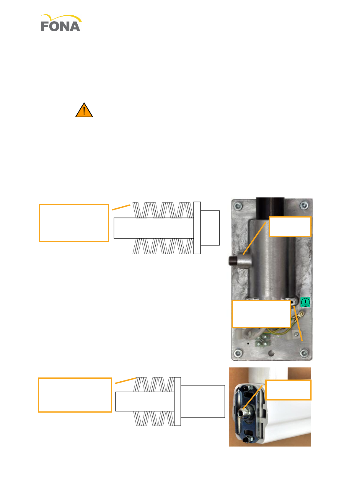
3.1.8 Mounting the Support Arm
AUnpack the support arm and check for completeness of parts.
BDo not remove the rope to pull the cable of the Scissor Arm to the Wall Adaptor through the Support
Arm.
CPush back the cylinder of the side friction not to interfere, lightly grease the shaft of the extension arm
and insert it into the wall adaptor.
DMount the rotation end-stop spacer and close the side friction without tightening.
FONA XDG –Service & Installation Manual
10/32 69 550 70210 150715
3.1.9 Mounting the Scissor Arm
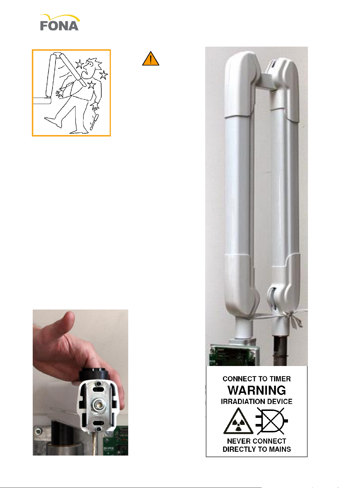
WARNING. THE SPRINGS IN
THE SCISSOR ARM MAY CAUSE
INJURY TO THE INSTALLER AS
WELL AS DAMAGE TO THE ARM
ITSELF IF NOT HANDLED
PROPERLY. DO NOT REMOVE
THE BINDING STRING UNTIL
WHEN NECESSARY
ALight grease the shaft at the base of the arm and make sure
the ring spacer is in place; push back the cylinder of the
friction into the support arm not to interfere during the
insertion of the shaft.
BSecure the trailing rope to the end of the electrical cable of
the Scissor Arm.
CPull the other end of the trailing rope to drive the electrical
cable of the Scissor Arm through the Support Arm out into
the Wall Adaptor.
DHold the opening section of the Scissor Arm, carefully
remove the safety string and allow the arm to open slowly,
away from people.
EPerform final set-up complying with recommended sequence
of actions reported in the following.
FONA XDG –Service & Installation Manual
150715 69 550 70210 11/32
3.1.10 Connecting the Wall Adaptor with Timer at side
APass the conductor of the grounding provision (already connected to the common bolt) into the timer
for connection to the central ground point in the connecting block (protective earthing).
BConnect the grounding provision of the extension arm to the common bolt on the wall plate (flat
washer, ground provision, lock-washer, nut).
CPass through the supply cable of the arm into the timer for connection to the OUT positions (supply
cable output to X-ray head).
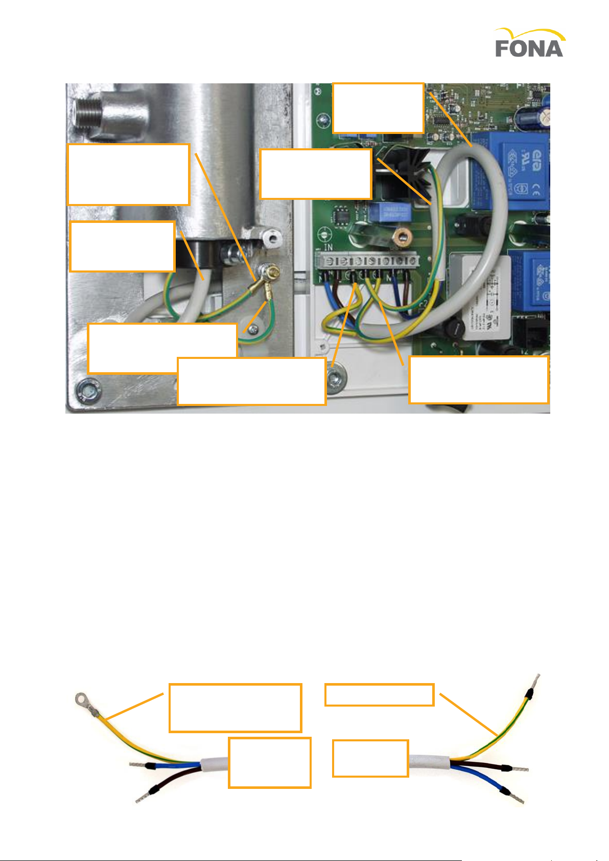
3.1.11 Connecting the Wall Adaptor with Timer remote
AIn case the connection to the mains is done starting from the wall adaptor a 5 position connection
block has to be mounted. This approach is recommended allowing for a lower ground resistance.
a The ground wire of the mains has to be connected in first position on the common bolt and
blocked with a nut.
b The mains line goes to the remote timer and back through the connection block to the X-ray head.
c The other grounding provisions for support arm and of cable returning from the timer to be
connected to the common bolt and blocked with a second nut.
d The ground resistance to consider is actually the one of the cable in the scissor arm.
BIn case the connection to the mains is done through the timer box, the ground resistance to consider
includes the wire from the timer to the wall adaptor.
a Prepare the terminations of the cable for remote connection of timer with tips to fit the connecting
blocks in timer and connecting blocks plus the common bolt for grounding in wall adaptor.
Make sure the copper section of the yellow green wire is large enough (see section 0,
Electrical Requirements, at page 7).
WALL
ADAPTOR
SIDE
TIMER
SIDE
YELLOW-GREEN TO
COMMON BOLT ON
WALL ADAPTOR
YELLOW-GREEN
SUPPLY CABLE
FROM TIMER
TO TUBE HEAD
YELLOW-GREEN
GROUND PROVISION
TO TIMER
YELLOW-GREEN
BONDING
CONDUCTOR OF
SUPPORT ARM
SUPPLY CABLE
OUTPUT TO
TUBE HEAD
YELLOW-GREEN
GROUND PROVISION
ON TIMER
MAINS LINE
INPUT TO
TIMER
YELLOW-GREEN
GROUND PROVISION
FROM MAINS
FONA XDG –Service & Installation Manual
12/32 69 550 70210 150715
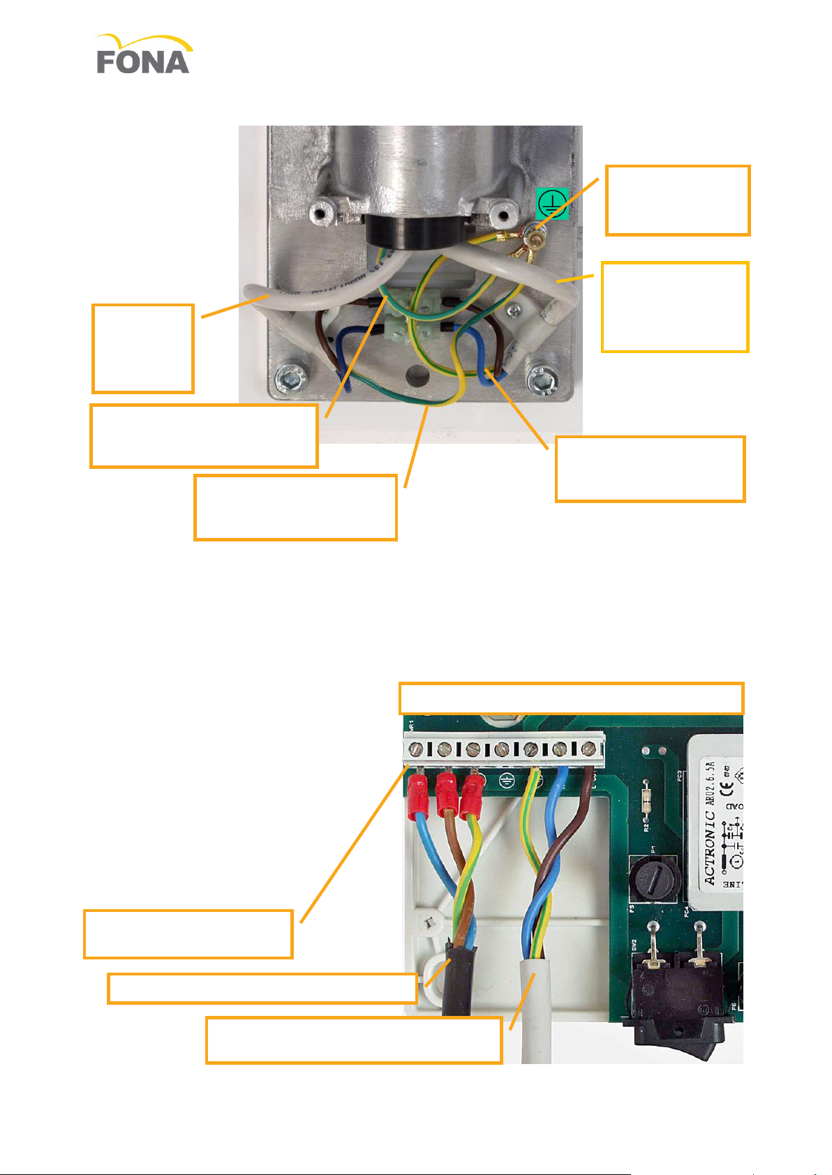
CRemove from the common bolt for bonding and grounding on the wall adaptor the existing cable for
ground provision.
DConnect the cable for remote connection of the timer by placing the ground wire as first conductor on
the common bolt for bonding and grounding; block with washers and nut.
EPlace the phase and neutral wires to the connecting block.
FConnect to the common bolt for bonding and grounding the bonding conductor of the extension arm
and the one of the cable of the arm.
GConnect the phase and neutral conductors of the supply cable in the arm to the connecting block.
See section 0,
HElectrical Requirements, at page 7 to determine cable length and maximum distance.
SUPPLY CABLE FROM REMOTE
TIMER TO TUBE HEAD
MAINS SUPPLY INPUT TO TIMER
CONNECTING BLOCK
IN THE TIMER
CONNECTIONS IN THE REMOTE TIMER
BOLT FOR
BONDING AND
GROUNDING
SUPPLY
CABLE
TO TUBE
HEAD
YELLOW-GREEN
GROUND PROVISION
FROM/TO TIMER
YELLOW-GREEN
BONDING CONDUCTOR
SUPPORT ARM
SUPPLY CABLE
FROM REMOTE
TIMER TO TUBE
HEAD
YELLOW-GREEN
BONDING CONDUCTOR
SCISSOR ARM
FONA XDG –Service & Installation Manual
150715 69 550 70210 13/32
3.1.12 Connecting the Timer
ATurn-off the voltage supply line. Connect the three wires from the voltage supply to the terminal
block (IN on the left) but do not connect any outgoing wire (OUT on the right) to Wall Adaptor.
BMake sure that the “live” conductor is the “hot” one:
a Connect an AC voltmeter or a test light between the block terminal “live in” and “ground”.
b Turn line voltage supply “ON”. If full line voltage is measured (test lamp lights) the wiring is
correct. If not turn line voltage supply “OFF”, reverse “live in” and “neutral in” wires and repeat the
measurement; eventually the full line voltage should be read between “line” and “ground” (test
lamp lights).
c Make sure no voltage is read between “neutral in” and “ground”; if not check line voltage
distribution.
CTest the timer for full functionality keeping the output cables disconnected not to supply the load.
DConnect the load.
a Turn OFF the line voltage supply line,
b Connect the three wires of additional cable outgoing to the Wall Adaptor, Arm, Tube Housing
Assembly. Live and neutral wires to the arm (X-ray head) can be interchanged.
Fuses of FONA XDG Timer
Ref.
115 V
230 V and 240 V
F1
6.3 AT 5x20
4 AT 5x20
F2
6.3 AT 5x20
4 AT 5x20
F3
315 mAT 5x20
315 mAT 5x20
F4
80 mAT 5x20
50 mAT 5x20
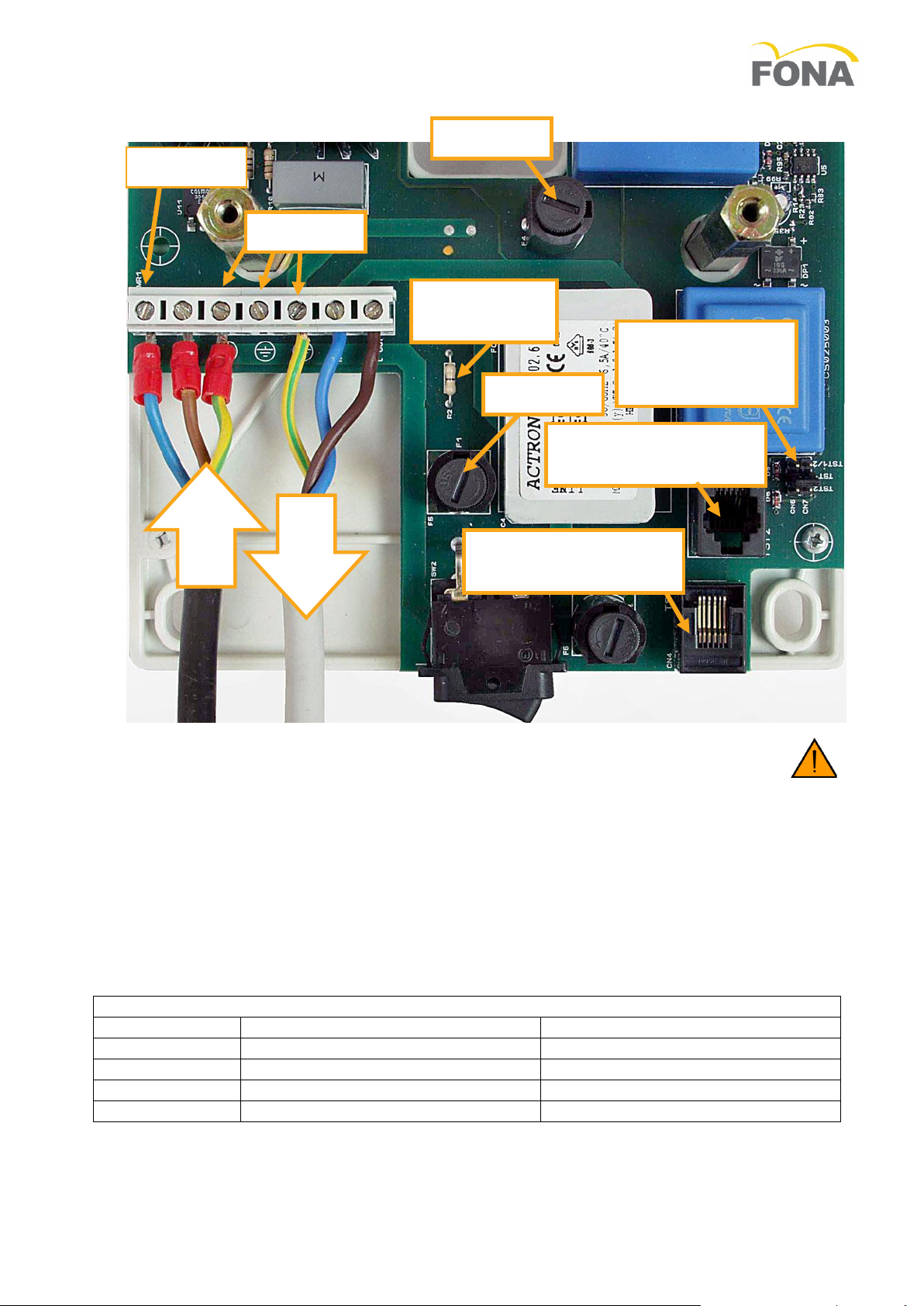
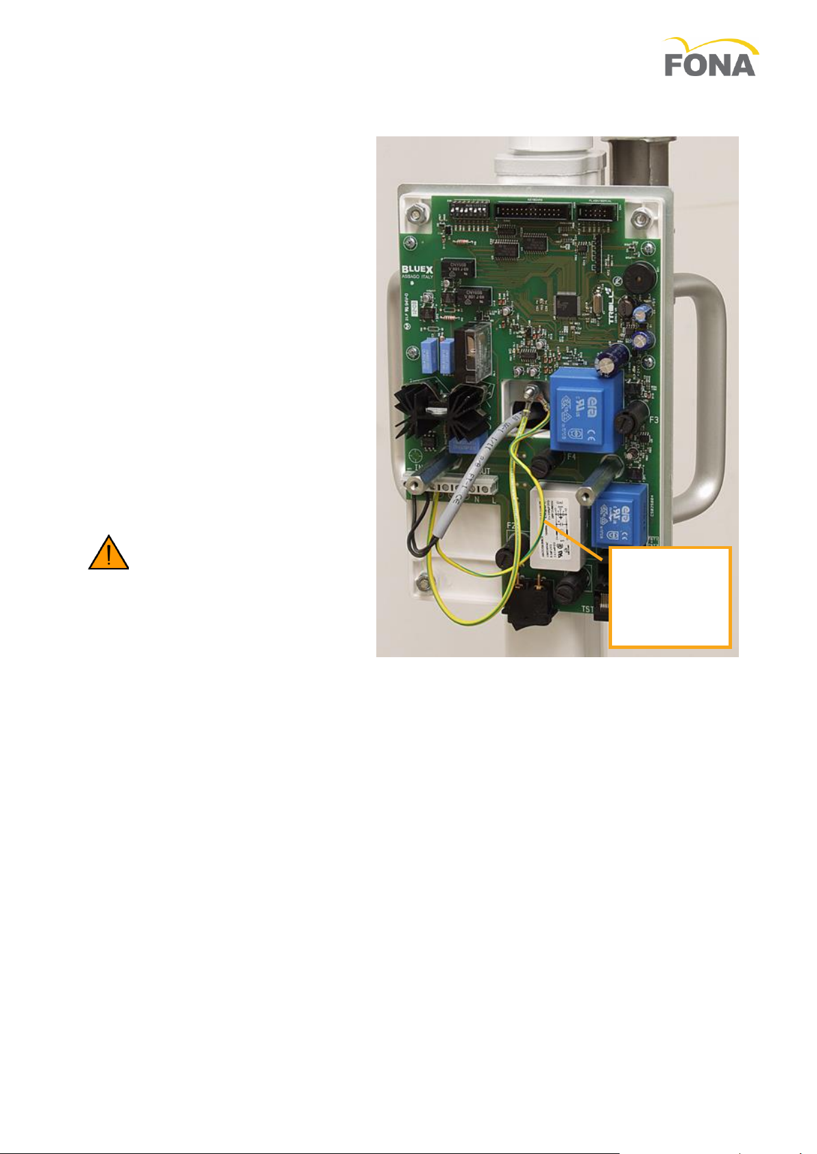
3.1.13 Connecting the Hand-Switch
AThe hand-switch is provided with a 3 m coiled cord to be plugged one side in the hand-switch, the
other side in the lower left corner of the timer’s board, either externally (connector TST1) or internally
to the timer (connector TST2). Internal connection is for remote hand-switch or for additional control
safety switches.
LIVE
FUSE F1
IN
HAND-SWITCH
CONNECTION
JUMPERS
HAND-SWITCH
SOCKET TST2
HAND-SWITCH
SOCKET TST1
FUSE F2
FUSE F4
ZERO OHM
RESITOR
OUT
GROUND
NEUTRAL

FONA XDG –Service & Installation Manual
14/32 69 550 70210 150715
BJumpers are available to activate properly the hand-switch connection:
a Position TST1 to enable external socketTST1,
b Position TST2 to enable the internal socket TST2,
c Position TST1/2 f to enable the internal and the external sockets.
3.1.14 Optional Remote Hand-Switch
The hand-switch can be remotely mounted by making use of the optional kit made of a remote box (wall
holder) and connection cable 10 m long.
The connection of the wires is here indicated.
The wires of the switch are number 3 and 4
(those in the middle of the connector).
3.1.15 Mounting and Connecting the X-ray Head
ARemove the handgrip pipe
from the arm and place it onto
the tube-head shaft of the
coupling yoke.
BLubricate the shaft, insert it
into the arm passing the
cables into the coupling yoke,
then hold it in place with the
retaining fork.
CAttach the connectors of the
supply and grounding wires
and push them into the side
opening of the coupling yoke.
DPull down the O-ring and
push-up the handgrip pipe,
then fix it in place with the
screw at bottom.
EVerify smooth movement of
the tube head around its
vertical and horizontal axis.
Tune side friction if necessary
referring to section 4.4,
Maintenance of X-ray Head, at
page 22 for details.
FMount the cover on the yoke opening eventually.
HANDGRIP
PIPE
RETAINING
FORK
COUPLING
YOKE
FONA XDG –Service & Installation Manual
150715 69 550 70210 15/32
3.1.16 Beam Limiting Device
AMount the beam limiting device on the tube-head and lock it close with a clock-wise rotation.
3.1.17 Final Tuning and Set-Up
ARemove the line voltage fuse(s) from the timer (Fuse 1 and Fuse 2).
BTune friction screw in Wall Adaptor for rotation of Support Arm (see section 4.1, Maintenance of Wall
Adaptor at page 20 for details).
CTune friction screw in Support Arm for rotation of Scissor Arm around it vertical axis (see section 4.2,
Maintenance of Support Arm at page 20).
DThe friction points in the scissor arm and those for the rotation of the X-ray head around its horizontal
axis are tuned in factory. Should you need to repeat the procedures refer to sections 4.3, Maintenance
of Scissor Arm, at page 21 and 4.4, Maintenance of X-ray Head, at page 22, respectively.
EMake sure the Timer switch is in the “OFF” position.
FSet the dip switches SW2 as indicated in the following to define:
a Enable/disable function for correction of exposure in presence
of line voltage fluctuations.
b The nominal line voltage of the X-ray head (see label).
c Set dip switch 4 to the anode current set in the X-ray head
label, which is 3.5 mA for FONA XDG.
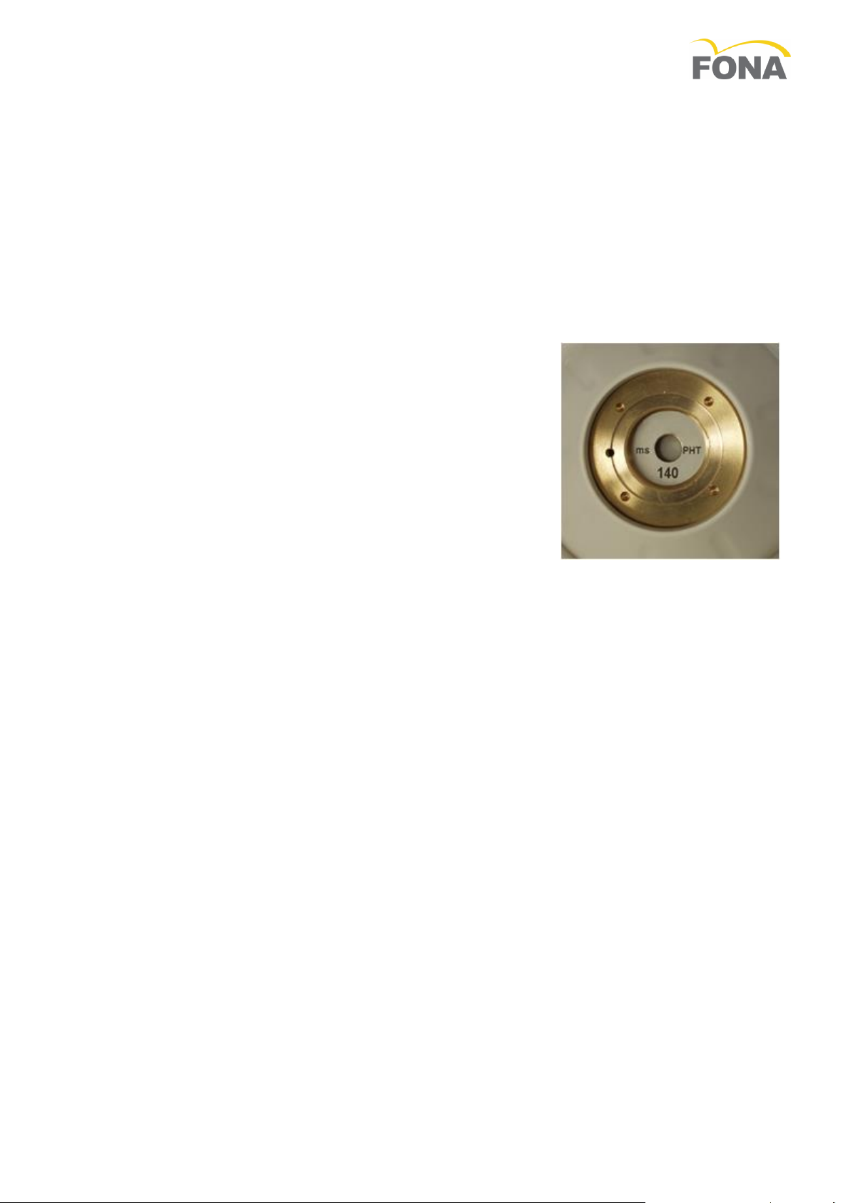
d Set the pre-heating time according to type of X-ray insert used
in the X-ray head assembly; the measured value is marked on
the X-ray head.
e Select the technique factor on display as mAs (always mAs for
the timer of FONA XDG).
GPut back the line voltage fuse(s).
HPut back all plastic covers and logo strips.
IConnect the system to the line voltage by switching the general line
voltage switch on and/or plug the power cord into the wall socket.
JSwitch the timer “ON”.
The system is now ready for functional checks.
FONA XDG –Service & Installation Manual
16/32 69 550 70210 150715
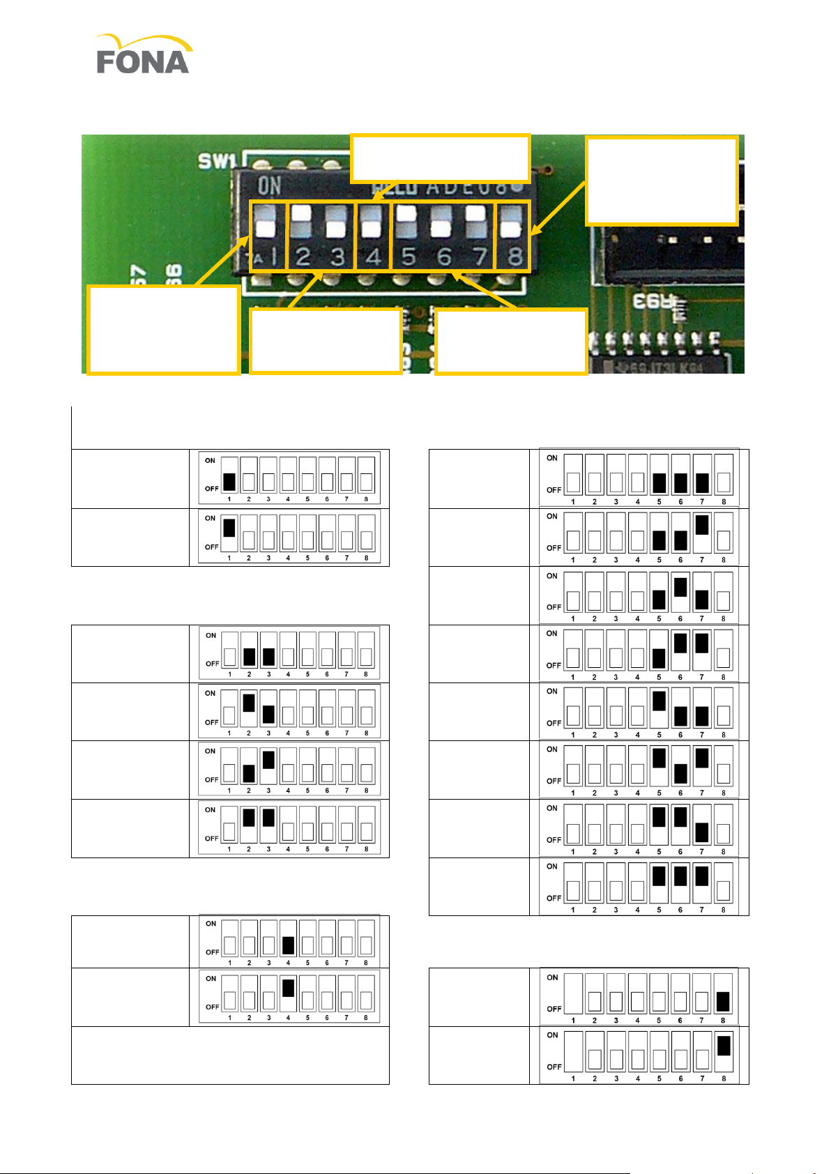
3.2 Dip Switch Setting
DIP 1
Technique Factor Correction
DIPS 5 –6 –7
Pre Heating Time
Disabled
100 ms
Enabled
120 ms
DIPS 2- 3
Tube Head Type
140 ms
110 or 220
VAC
160 ms
115 or 230
VAC
180 ms
120 or 240
VAC
200 ms
127 or 250
VAC
220 ms
DIP 4
Tube Head Anode Current
240 ms
3.5 mA
DIP 8
Technique Factor Displayed
7 mA
s
mAs
DIPS 2-3
TUBE HEAD
TYPE
DIP 4
ANODE CURRENT
DIPS 5-6-7
PRE HEATING
TIME
DIP 8
TECHNIQUE
FACTOR
DISPLAYED
DIP 1
TECHNIQUE
FACTOR
CORRECTION
FONA XDG –Service & Installation Manual
150715 69 550 70210 17/32
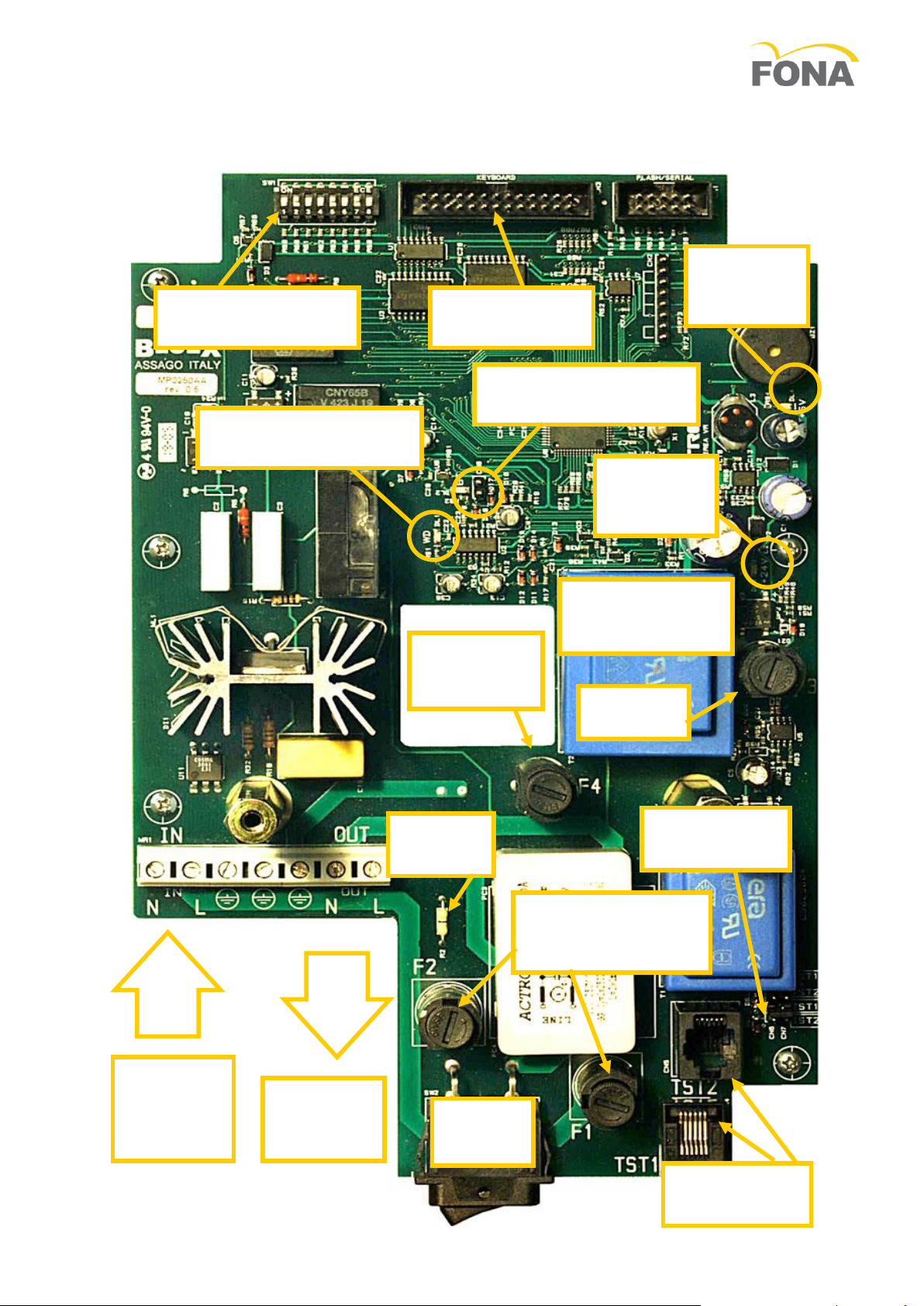
3.3 Layout Power Board Timer
SET-UP
MICROSWITCHES
KEYBOARD
CONNECTOR
POWER
SUPPLY
5 V LED
BACK UP TIMER
TEST POINT & LED
MICROPROCESSOR
WATCH DOG LED
FUSE 4
T50mA @230V
T80mA @115V
POWER
SUPPLY
24 V LED
FUSE 3
T 315 mA
OUTPUT
LINE TO
TUBEHEAD
INPUT
MAINS LINE
NEUTRAL
& LIVE
JUMPER
FUSE 2
HANDSWITCH
SOCKETS
MAINS
SWITCH
HANDSWITCH
JUMPERS
FUSE 1 & FUSE 2
T4A @230V
T6.3A @115V
5VA TRANSFORMER
PRIMARY 115/230 V
SECONDARY 18 V
FONA XDG –Service & Installation Manual
18/32 69 550 70210 150715
3.4 Mobile Systems
3.4.1 Unpacking
Unpack the components of the system and check the following:
AEach item is in good conditions and was not damaged during transportation.
BAll the items for the desired system configuration are available.
CThe line voltage on the labels of timer and X-ray head correspond to the existing local
line voltage.
3.4.2 Room Preparation
Make sure that a wall socket is available close to the dental chair in reach of the mobile X-
ray equipment.
Such a socket has to be provided with connection to the protective grounding.
The line voltage cable can come without plug to be added according to the local standard.
3.4.3 Mounting and Connecting Sequence
Step 1
Assemble the Mobile Stand
Step 2
Mount the Scissor Arm
Step 3
Mount the Scissor Arm
Step 4
Mount the Timer
Step 5
Connect the Line Voltage Cable
Step 6
Connect the Timer
Step 7
Activate second Fuse
Step 8
Mount and connect X-ray head
Step 9
Mount the collimator
Step 10
Final Tuning and Set-Up
3.4.4 Assembling the Mobile
Stand
AMount the legs below the central base.
BMount rear wheels and front wheels with brakes.
CAttach the pole with timer plate.
DComplete the stand with cable holder and
handles
3.4.5 Mounting the Arm
ALoosen the friction and push back the cylinder of
the same not to interfere during shaft insertion.
BInsert the arm. Refer to section 3.1.9 at page 10
for details.
FONA XDG –Service & Installation Manual
150715 69 550 70210 19/32
POWER
SUPPLY
CORD
BONDING
CONDUCTOR
3.5 Mounting the Timer
The timer is blocked in place with four bolts.
3.5.1 Connecting the Line
voltage cable
AThe line voltage cable for the mobile has
to be completed with local plug.
BThe power supply cord bonding
conductor has to be blocked (first) to the
common bolt for bonding and grounding
using lock-washer and nut.
CThe grounding wire for the timer is then
placed on the same common bolt and
blocked (second) with lock- washer and
nut.
DConnect the grounding wire for the timer
to the ground provision on the terminal
block of the timer and the two line wires
of the power cord to the input points of
the terminal block of the timer.
3.5.2 Connecting the Timer
For the connection of the output cable to the
timer please refer to section 3.1.11 at page
13.
3.5.3 Activation of Fuse 2
Units provided with supply cord and
plug must be equipped with fuses
on both line phases. The activation
on the second fuse is done by cutting the
Jumper Fuse 2 (zero Ohm resistor) close to
Fuse F2. See position on layout in section 0
at page 17.
3.5.4 Mounting and Connecting the X-ray Head
Refer to section 3.1.15 at page 14.
3.5.5 Mounting the Beam Limiting Device
Refer to section 3.1.16 at page 15.
3.5.6 Final Tuning and Set-Up
Refer to section 3.1.17 at page 15.
FONA XDG –Service & Installation Manual
20/32 69 550 70210 150715
FRICTION
SCREW
4. MAINTENANCE
Here in the following the list of recommended maintenance actions to keep the FONA XDG system in
compliance with the Performance Standard.
It is the responsibility of the User to maintain the equipment in compliance with the standard. Failure of
the User to properly maintain the equipment may relieve the Manufacturer, or its Agent, from responsibility
for any injury, damage or non compliance which may result.
Maintenance for the FONA XDG system to be done regularly by a service technician at least once every 24
months, with regular checks performed by the operator every year.
Any defect or malfunction should be corrected immediately by qualified personnel with adequate training.
WARNING.
Any defective item affecting A safe use must be repaired or replaced
Only original certified components and spare parts must be used for repairs or replacements.
Correction of damages to the identification labels to be handled with the Manufacturer. Any defect or
non-compliance must be reported promptly to the Manufacturer or to its Local Agent.
Always disconnect the system from the line voltage supply using the general line voltage switch for the
room where the equipment is located before performing any maintenance activity
Avoid using liquid or spray detergents which may enter into the equipment and cause corrosion.
Avoid the use of solvents or corrosive detergents which can damage painted surfaces and plastic
covers.
4.1 Maintenance of Wall Adaptor
ARemove the cover and verify that the mounting is closely
connected to the wall and stays firm and steady during the
movements of the system.
BVerify for proper connection of grounding wires to the common
bolt.
CCheck friction during rotation of Extension Arm and adjust if
needed.
DVerify that the technical label with identification data outside the
plastic cover at bottom is in place and is readable.
4.2 Maintenance of Support Arm
ASlide partially out the extension arm from wall mount, inspect for
wear of the joint and lubricate for smooth rotation.
BCheck friction during rotation of Arm and adjust relevant screw if
needed.
CVerify that the technical label with identification data is in place and is readable.
POSITION OF 21
DISK SPRINGS IN
FRICTION SCREW
7 GROUPS OF 3
BOLT FOR
BONDING AND
GROUNDING
FRICTION
SCREW
POSITION OF 15
DISK SPRINGS IN
FRICTION SCREW
5 GROUPS OF 3
Other manuals for XDG
1
Table of contents
Other Fona Dental Equipment manuals


Popular Dental Equipment manuals by other brands

Belmont
Belmont IO 5000TA Installation and operation instructions

Straumann
Straumann Novaloc technical information

KaVo
KaVo MASTERmatic LUX M10 L Instructions for use

Intensiv
Intensiv Ortho-Strips Opener Instructions for use and safety recommendations

Forest Dental
Forest Dental Fusion 3800 Installation instruction

VHF
VHF S5 operating instructions


AcceleDent
AcceleDent Optima Quick reference guide

Carestream DENTAL
Carestream DENTAL CS 8200 3D user guide

ETEKCITY
ETEKCITY EWF-32 user manual

Acteon
Acteon SOPRO 717 FIRST user manual

Bien Air
Bien Air OPTIMA INT installation instructions

Dentsply Maillefer
Dentsply Maillefer START-X A0660 Directions for use