Fondital Gazelle EVO Series Quick start guide

Gas convective stoves
INSTALLATION, USE AND MAINTENANCE INSTRUCTIONS
CE 0051
It is compulsory to read this manual before proceeding with the installation, use and maintenance operations.
The intended use of this gas equipment is the direct heating of the rooms in which it is installed, within residential, civil, commercial
and industrial buildings.
Any other use is forbidden, including heating of technical rooms.
Have an Authorised Service Centre ll out the inspection certicate.
IST 03 G 046 - 01
EN

2
Dear Sirs,
Thank You for choosing and buying one of our products. Please read these instructions carefully in order to properly install, operate,
and maintain the product.
WARNING
We inform users that:
• Equipment shall be installed by an authorised company under the requirements set forth by the prevailing rules, in full
compliance with the prevailing regulations and standards.
• Anyone entrusting installation to an unqualied installer will be subject to administrative sanctions.
• Equipment must be maintained by qualied personnel only, under the requirements set forth by the prevailing rules.

3
1. GENERAL NOTES FOR INSTALLING AND MAINTENANCE TECHNICIANS, AND USERS
This instruction manual is an integral and essential part of the product. It shall be supplied by the installer to the user who shall keep
it carefully to consult it whenever necessary.
This document shall be supplied together with the equipment in case the latter is sold or transferred to others.
Any reference to law, regulations or standards in this manual is for information purposes and only refers to the date of going to print.
WARNING
The intended use of this gas equipment is the direct heating of the rooms in which it is installed, within residential, civil,
commercial and industrial buildings.
Any other use is forbidden, including heating of technical rooms.
WARNING
This equipment must be installed by qualied personnel.
Qualied personnel includes staff having specic technical competence in the eld of parts of heating systems for civil
use, or qualied according to prevailing law.
The installation by unqualied personnel is forbidden.
WARNING
This equipment must be installed in compliance with the requirements of the technical standards and legislation in force
relating to gas appliances, particularly with reference to ventilation of the premises.
Any installation that does not comply with the requirements of the technical standards and legislation in force is forbid-
den.
WARNING
This equipment must be installed according to the manufacturer’s instructions given in this manual. Incorrect installation
may cause injury to persons and/or animals and damage to property. The manufacturer shall not be held liable for any
such injury and/or damage.
WARNING
This equipment must be correctly and safely connected to an electrical system compliant with the existing technical
standards.
Any incorrect and unsafe connection to the electrical system is forbidden.
It is forbidden to connect the boiler to an electrical system lacking a differential switch to protect the equipment power
line.
Any connection to an electrical system lacking a proper grounding system is forbidden.
WARNING
The equipment is supplied with a three-poled power cable, already connected to the electronic board and it is provided
with a safety clamp.
This equipment must be connected to a 230V power supply network, as indicated on the label afxed to the power cable.
4
WARNING
This equipment must be connected to a gas distribution system which complies with the existing technical standards.
Check the gas system state of conservation before installing the equipment.
Any connection to a gas system which does not comply with the existing technical standards is forbidden.
When connecting the equipment to gas supply network, it is compulsory to install an appropriately sized gasket made
from suitable material.
The boiler gas inlet coupling is not suitable for hemp, teon tape or similarly made gaskets.
After connecting the equipment, check the connection for tightness.
Once gas is in the pipes, leak test by a naked ame is forbidden; use specic products available on the market.
WARNING
With gas red boilers, take the following measures if you smell gas:
• Do not turn on or off electric switches and do not turn on electric appliances.
• Do not ignite ames and do not smoke.
• Close the main gas tap.
• Open doors and windows.
• Contact a Service Centre, a qualied installer or the gas supply company.
Never use a ame to locate a gas leak.
WARNING
Carefully read the instructions relating to air intake and ue gas venting systems in the specic section of this manual.
WARNING
It is compulsory to use the supplied seals to seal the equipment intake and vent pipes.
WARNING
It is compulsory to fasten the intake and vent terminals to the external wall using the supplied screws.
WARNING
The equipment is designed for installation in the countries indicated on the technical data plate which is applied both to
the package and the equipment itself: installation in any other country may be a source of danger for people, animals
and/or property.
The manufacturer will bear no contractual and tortious liability for failure to comply with all the instructions above.
WARNING
In the event of long periods of inactivity of the boiler, disconnect it from the electrical power mains and close the gas tap.
After removing the packaging, make sure that the content is not damaged. When in doubt, do not install the equipment and contact
the supplier.

5
WARNING
Packaging elements (cardboard, clips, plastic bags, foam polystyrene, etc.) should not be left within the reach of children
as they are potential hazard sources.
WARNING
To ensure equipment safe, efcient and proper operation, have qualied personnel carry out an annual maintenance.
Only use original parts for all repairs to the equipment.
WARNING
In the event of failure and/or faulty functioning, switch off the equipment. Do not attempt to make repairs: contact qualied
technicians.
WARNING
Manufacturer's liability is excluded for loss or damage to persons, animals and/or property resulting from or consequent
to an evident danger for the user because, as such, it would have been avoidable by disconnecting the power supply and
closing the gas tap.
The user is strongly advised to contact one of the Manufacturer’s authorised Service Centres, as they are fully qualied for carrying
out spot-on repairs and maintenance.
WARNING
The user may only access parts of the equipment that can be reached without using special equipment or tools. The user
is not authorised to remove the equipment casing or to operate on any internal parts.
The user can use the equipment only when casing is installed and fastened.
WARNING
The manufacturer cannot be held responsible for any damage caused by inappropriate equipment installation or operation,
modication to the equipment, or due to failed/poor maintenance, non-observance of the instructions provided by the
manufacturer or of legislation and standards applicable for the materials installed.

6
1. GENERAL NOTES FOR INSTALLERS, MAINTENANCE TECHNICIANS, AND USERS ....................................................... 3
2. INSTRUCTIONS FOR USER..................................................................................................................................................... 7
2.1 Control panel........................................................................................................................................................................ 7
2.2 Equipment operation............................................................................................................................................................ 8
2.2.1 Equipment start-up................................................................................................................................................... 8
2.2.2 Equipment shutdown................................................................................................................................................ 8
2.2.3 Temperature setting.................................................................................................................................................. 9
2.2.4 Automatic operation ................................................................................................................................................. 9
2.2.5 Current time and date setting................................................................................................................................... 9
2.2.6 Customised programming ........................................................................................................................................ 10
2.2.7 Keypad locking function ........................................................................................................................................... 11
2.2.8 Summer ventilation function..................................................................................................................................... 12
2.2.9 Delayed switch-off function ...................................................................................................................................... 12
2.2.10 Equipment switch-off ................................................................................................................................................ 12
2.3 Humidication tank............................................................................................................................................................... 12
2.4 Precautions for use .............................................................................................................................................................. 13
2.5 Maintenance ........................................................................................................................................................................ 13
2.5.1 Cleaning the casing.................................................................................................................................................. 13
3. TECHNICAL FEATURES AND DIMENSIONS .......................................................................................................................... 14
3.1 Technical features ................................................................................................................................................................ 14
3.2 Dimensions and distances ................................................................................................................................................... 15
4. INSTRUCTIONS FOR INSTALLER........................................................................................................................................... 16
4.1 Choosing the positioning...................................................................................................................................................... 16
4.2 Installation............................................................................................................................................................................ 17
4.2.1 Straight wall vent...................................................................................................................................................... 18
4.2.2 Vent pipe with extensions or elbows ........................................................................................................................ 18
4.2.3 Roof vent.................................................................................................................................................................. 20
4.2.4 Intake and vent pipe length ...................................................................................................................................... 21
4.3 Connection to gas mains ..................................................................................................................................................... 24
4.4 Connection to the electrical mains ....................................................................................................................................... 25
4.5 Wiring diagram..................................................................................................................................................................... 26
4.6 Connecting a remote ambient temperature probe (option).................................................................................................. 27
4.7 Connecting a window contact (option) ................................................................................................................................. 27
4.8 Operations to change gas type ............................................................................................................................................ 28
4.8.1 Changing the gas nozzle.......................................................................................................................................... 28
4.8.2 Setting the gas type.................................................................................................................................................. 29
4.8.3 Checking the offset................................................................................................................................................... 29
4.8.4 Combustion analysis ................................................................................................................................................ 30
5. MAINTENANCE......................................................................................................................................................................... 31
5.1 Routine maintenance ........................................................................................................................................................... 31
5.2 Extraordinary maintenance .................................................................................................................................................. 32
6. DECOMMISSIONING, DISASSEMBLY AND DISPOSAL......................................................................................................... 33
7. TROUBLESHOOTING............................................................................................................................................................... 34
8. TECHNICAL SPECIFICATIONS TABLES - GAZELLE EVO.................................................................................................... 36
9. MANUFACTURER'S DECLARATION OF CONFORMITY........................................................................................................ 43
10. SEQUENCE FOR INSTALLING A STRAIGHT WALL VENT.................................................................................................... 44
CONTENTS
7
3000
5000
7000
0 1 3 5
1
2
3
4
5
6
7
7 9 11 13 15 17 19 21 23
2. INSTRUCTIONS FOR THE USER
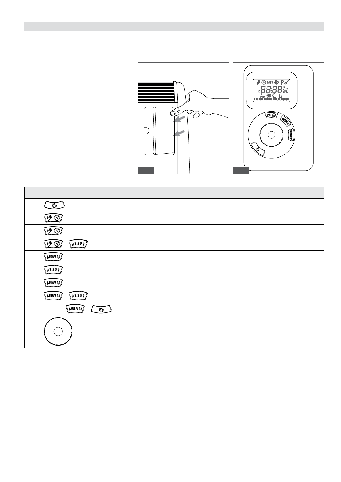
2.1 Control panel
Push on the right-hand side to open the control panel door, as shown in the gure.
Key Mode
ON/OFF
Manual operation / Automatic operation
(5sec) Delayed switch-off function
+(5 sec) Flue cleaning function
Menu
Resume operation
(10 sec) Keypad lock
+(5 sec) Programming the main board parameters
When off +Programming the display parameters
Parameters and temperature setting knob
Fig. 1 Fig. 2
8
2.2 Equipment operation
2.2.1 Equipment start-up
Open the gas tap.
Make sure that the equipment is connected to the power mains.
OFF is displayed.
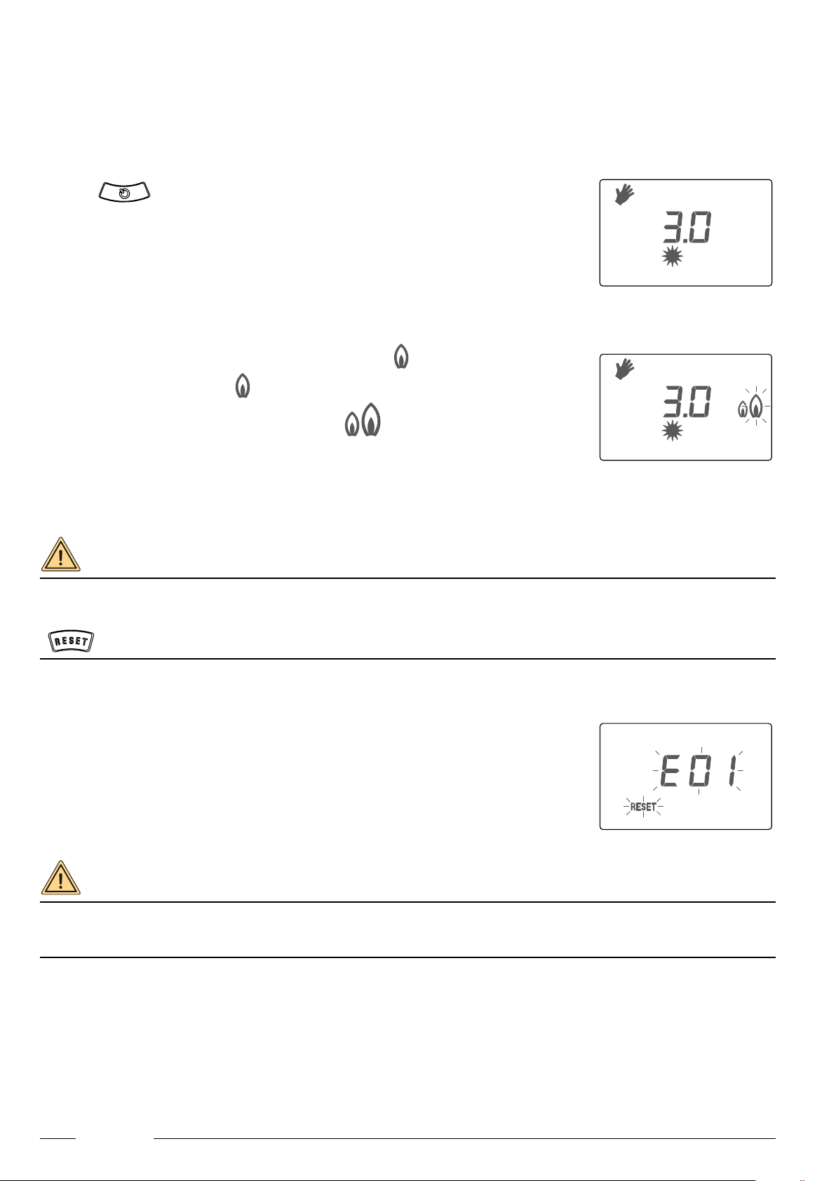
Press key to switch equipment on in manual mode: switch-on is
indicated by 2 “beeps” and the display shows:
- equipment model at bottom right: 3000, 5000 or 7000
- a hand indicating manual mode at top left
- two central digits indicating the set temperature level
- the sun indicating that equipment is in comfort mode
In manual mode, the equipment stays always on until the set temperature level is achieved.
When there is a request for burner ignition, the ashing symbol is displayed.
When the burner is on, the symbol is steady on.
When the burner is on at maximum power, the symbol is displayed.
The second ame blinks when toggling between operation at minimum power and operation at
maximum power.
To set desired temperature, see par. 2.2.3. Temperature setting.
To set equipment operation to automatic mode, see par. 2.2.4. Automatic operation.
WARNING
If the equipment is started after a long period of inactivity, especially for models running on propane, it is possible to
experience an initial hard starting.
This means that the equipment could shut down once or a few times and make it necessary for you to reset it through key
: if display shows E99, please read paragraph 7. TROUBLESHOOTING.
2.2.2 Equipment shutdown
The equipment shuts down automatically if a malfunction occurs.
Shutdown is indicated visually by ashing message E## (where ## indicates the error code) and
acoustically by a sequence of 3 “beeps” with a 10 second gap, throughout the time of equipment
shutdown.
If shutdown can be reset by the user, the display will also show RESET ashing message.
In case of equipment shutdown, please read paragraph 7. TROUBLESHOOTING.
WARNING
The user must strictly comply with the relevant instructions (see column “For the user” of the table in paragraph 7.
TROUBLESHOOTING).
The user must NOT follow the instructions from the column “Only for qualied staff”.
3000
3000
3000

9
2.2.3 Temperature setting
The devices are equipped with an on-board temperature probe able to detect the temperature of the room where they are installed: it
is possible to install a remote probe for a better reading and setting of the ambient temperature (for the installation of a remote ambient
temperature probe see paragraph 4.6. Connecting a remote ambient temperature probe).
The display does not show the actual ambient temperature, but a level from 0 to 6, corresponding
to an ambient temperature value ranging from a minimum of 5 °C (level 0) to a maximum of 35 °C
(level 6).
Level 3 approximately corresponds to a temperature of 20 °C.
The antifreeze function is triggered at level 0 so that the equipment restarts any time ambient
temperature goes below 5 °C.
Turn knob clockwise to increase the temperature level; turn knob counter clockwise to decrease the
temperature level. When you turn the knob, the temperature level value will ash. Press the knob to
conrm the selected value or wait until the value stops ashing.
In automatic mode, two different temperature level values can be set: Comfort and Reduced (see
paragraph 2.2.6. Customised programming).
2.2.4 Automatic operation
Press to set equipment to automatic operation, which provides a weekly schedule and two
values for the temperature level: Comfort and Reduced.
The Comfort temperature level is represented by the sun symbol , while the Reduced temperature
level by the moon symbol .
The equipment is supplied with a preset factory schedule:
- Comfort temperature level : 3.5
- Reduced temperature level : 0.0
- Monday to Friday: Comfort level from 7:00 am to 9:00 am and from 5:00 pm to 9:00 pm
- Saturday and Sunday: Comfort level from 8:00 am to 9:00 pm
To set a customised schedule, see paragraph 2.2.6. Customised programming.
2.2.5 Current time and date setting
Set current time and date as follows:
- press key
- turn the knob and select the settings symbol
- press knob to conrm
- hours are displayed ashing
- turn knob until setting current hour
- press knob to conrm
- minutes are displayed ashing
- turn knob until setting current minutes
- press knob to conrm
- on the LH side of the display is a number indicating the day of the week
- turn knob to select the current day (1 = Monday)
- press knob to conrm
- to quit the current time setting mode, press .
3000
3000
1
01 35
1
7911 13 15 17 19 21 23
3000

10
2.2.6 Customised programming
The equipment allows you to program a customised schedule replacing the factory default one.
Programming a schedule means:
- setting periods of time when equipment keeps a Comfort temperature (represented by the sun symbol )
- setting periods of time when equipment keeps a Reduced temperature (represented by the moon symbol )
Resolution is 30 minutes: every day is broken down in 48 time intervals.
Set customised programming schedule as follows:
- press key
- turn knob and select the symbol P
- press knob to conrm
Selecting temperature levels
After conrming symbol P:
- the sun symbol and the Comfort temperature value are displayed ashing
- turn knob until reaching the required temperature level
- press knob to conrm
- the moon symbol and the Reduced temperature value are displayed ashing
- turn knob until reaching the required temperature level
- press knob to conrm
Selecting the day or a group of days for the schedule
After conrming the temperature levels:
- on the LH side of the display is a number indicating day 1 (Monday), ashing
- turn knob to highlight:
» in a sequence the numbers for the week days (1 = Monday), then
» a group with the ve work days (1-2-3-4-5), then
» a group with the two weekend days (6-7), then
» a group with all week days (1-2-3-4-5-6-7)
- select the required day or group and press knob to conrm.
Setting the schedule
After conrming the day or group of days to program:
- at the centre of the display are four digits representing the programming interval: every day is split
into 48 intervals (one every half an hour).
- at the bottom of the display is the programming bar made up of 48 points with the indication of the
hours in a day below, and segments above;
- the presence of a segment means the equipment is operating at the Comfort temperature; the
absence of the segment means the equipment is operating at the Reduced temperature
- turn knob to shift cursor
- press knob once and the sun symbol appears
- press knob a second time and the moon symbol appears
- press knob a third time and no symbol appears
- if you press it again, this sequence will roll over again
• no symbol means that the knob can be used to scroll the programming bar without changing the schedule
• sun symbol present allows setting the operating periods at Comfort temperature level
• moon symbol present allows setting the operating periods at Reduced temperature level
- after selecting the sun symbol or the moon symbol according to required equipment operation, turn knob to select the period
of interest and press knob to conrm. This operation must be repeated for all periods of interest, for the selected days or groups of
days
- press key to save the schedule for the current day or group of days
- select another day or group of days to be programmed and repeat the above-described sequence or quit programming by pressing
key
0 1 3 5
1
7 9 11 13 15 17 19 21 23
1
11
Example
Comfort Temperature : 3.5
Reduced Temperature : 2.0
Programming: .. Monday to Friday: Comfort temperature from 6:00 am to 8:00 am and from 4:00 pm to 8:00 pm
Saturday and Sunday: Comfort temperature from 8:00 am to 8:00 pm
- press key
- turn knob and select the symbol P
- press knob to conrm
- the sun symbol and the Comfort temperature value are displayed ashing
- turn knob until reaching the 3.5 temperature level
- press knob to conrm
- the moon symbol and the Reduced temperature value are displayed ashing
- turn knob until reaching the 2.0 temperature level
- press knob to conrm
- on the LH side of the display is a number 1 (Monday), ashing
- turn knob until displaying the group of ve work days (1-2-3-4-5)
- press knob to conrm
- at the centre of the display are four digits representing the programming interval
- at the bottom of the display is the programming bar made up of 48 points with the indication of the hours in a day below, and
segments above
- press knob twice: the moon symbol appears
- turn knob clockwise until time 6:00 is displayed
- press knob twice: the sun symbol appears
- turn knob clockwise until time 8:00 is displayed
- press knob once: the moon symbol appears
- turn knob clockwise until time 16:00 is displayed
- press knob twice: the sun symbol appears
- turn knob clockwise until time 20:00 is displayed
- press knob once: the moon symbol appears
- turn knob clockwise until time 23:30 is displayed
- press knob once to conrm
- press key to save the schedule and go back to day selection
- on the LH side of the display is a number 1 (Monday), ashing
- turn knob until displaying the group of two weekend days (6-7)
- press knob to conrm
- press knob twice: the moon symbol appears
- turn knob clockwise until time 8:00 is displayed
- press knob twice: the sun symbol appears
- turn knob clockwise until time 20:00 is displayed
- press knob once: the moon symbol appears
- turn knob clockwise until time 23:30 is displayed
- press knob once to conrm
- press key twice to save the schedule and quit programming
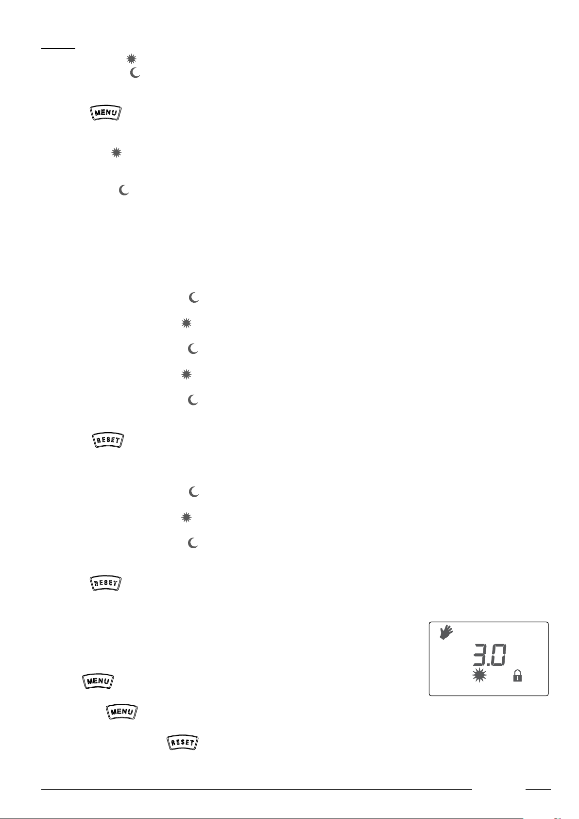
2.2.7 Keypad locking function
Equipment keypad can be locked.
This feature is useful to avoid that any unauthorised person, children for instance, could change the
schedule and settings of the equipment.
Press key for 10 seconds to lock the keypad: the display shows the lock symbol.
Press again key for 10 seconds to unlock the keypad.
When keypad is locked, the key remains active.
3000
12
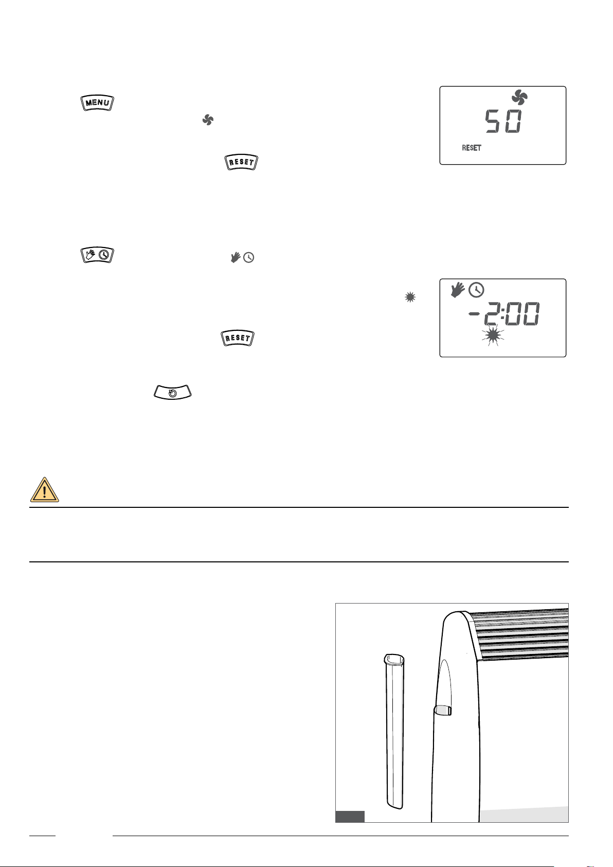
2.2.8 Summer ventilation function
The equipment features a summer ventilation function.
This function moves the ambient air but is NOT cooling it.
Activate the summer ventilation function as follows:
- press key
- turn the knob and select the fan symbol
- press knob to conrm
- turn knob to set fan speed: select a speed level from 0 (minimum) to 100 (maximum)
- to quit the summer ventilation function, press .
2.2.9 Delayed switch-off function
The equipment features a delayed switch-off function.
This function allows user to set occasional equipment operation for a dened time, with a 15-minute resolution.
Activate the delayed switch-off function as follows:
- press key for 5 seconds until symbols are displayed
- turn knob and set equipment operation time for a maximum of 8 hours
- press knob to conrm
- after this conrmation, the equipment starts a countdown of the set time: the sun symbol will
be ashing for this time period
- set required temperature level
- to quit the delayed switch-off function, press .
2.2.10 Equipment switch-off
With equipment on, press key to switch it off. Switch-off is acoustically indicated by 1 “beep”, the display will switch off and
show OFF.
2.3 Humidication tank
On equipment LH side is a removable plastic pocket that works as humidication tank. If the environment where equipment is installed
needs humidication, take the tank out of its housing, ll it with water and put it back.
DANGER
Remove tank from its housing before lling it.
Do not ll the tank when still in its housing.
During this operation, do NOT spill any water inside the equipment, especially through the top grille!
Danger of electric shock!
3000
3000
Fig. 3
The humidication tank is handed, with tank opening tilt determining the
proper insertion position.
Make sure to t the tank to its housing in the proper direction.
13
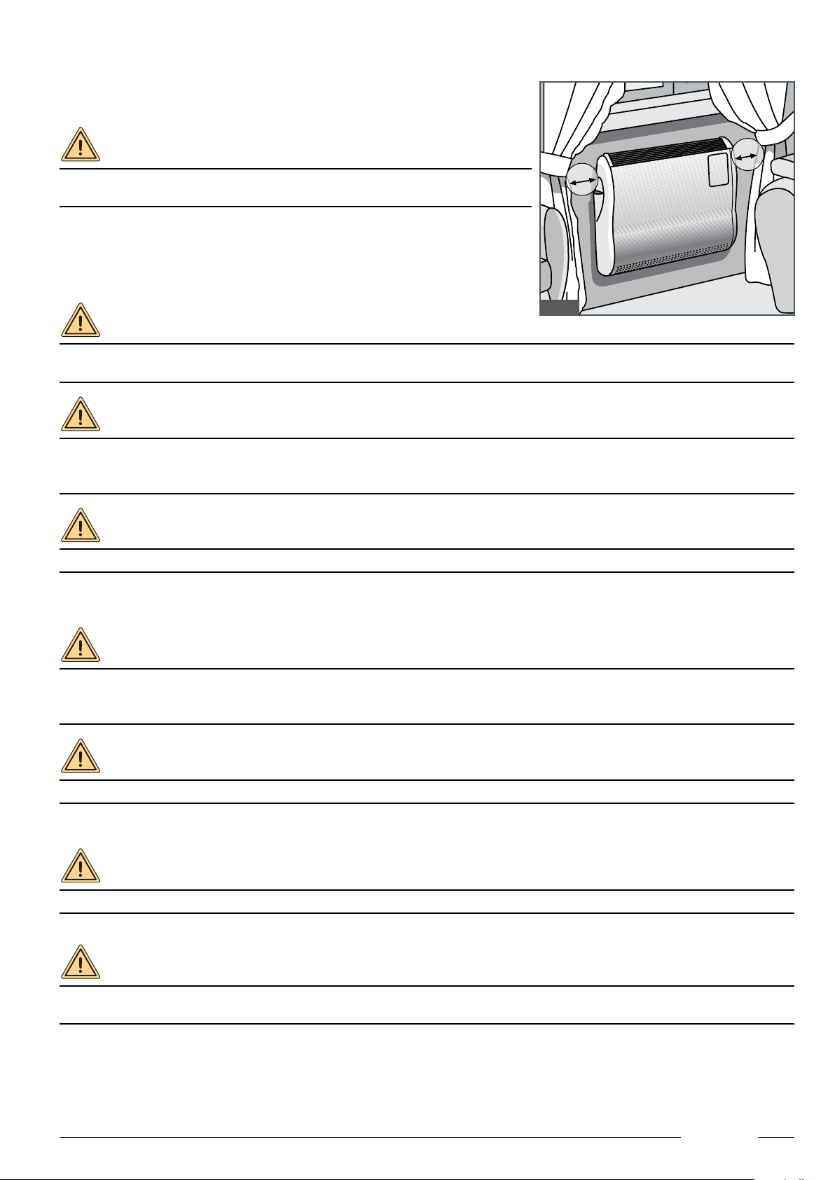
2.4 Precautions for use
Absolutely avoid covering casing grilles with foreign objects such as curtains, linen,
newspapers or other.
WARNING
Do not use the equipment to dry moist garments. Do not set moist garments
against the equipment.
If the mounting wall features curtains or curtaining, make sure to comply with the
following precautions:
• mobile curtaining: draw it before switching equipment on and make sure it is
approx. 30 cm away, on both sides of the equipment;
• xed curtaining: curtain bottom edge must be at about 30 cm from the equipment.
DANGER
Danger of electric shock! Never put a container with water onto the equipment as the latter could get damaged if water
is spilt.
DANGER
Danger of burns. With equipment on, do not touch the hot air outputs.
If there are any unsupervised children or incapacitated persons in the environment, it is advisable to have additional
protections installed, such as aesthetic grilles, in order to prevent contact with the equipment air intakes.
WARNING
When equipment is off and should be left out of service for a long time, close gas tap and cut out power supply.
2.5 Maintenance
WARNING
Routine boiler maintenance should be performed according to the schedule in the relevant section of this manual.
Appropriate maintenance is material to ensure equipment efcient operation, environment protection, and safety for
people, animals and property.
WARNING
Equipment must be maintained by qualied personnel only, under the requirements set forth by the prevailing regulations.
2.5.1 Cleaning the casing
WARNING
The casing can be cleaned by the user, when equipment is not operating, cold and disconnected from the mains.
Clean the casing and grilles using specic products: spray for furniture or a cloth moistened with alcohol.
WARNING
Never use water, liquid detergents or abrasive products that could damage the paint. Use of water or liquid detergents
could cause a danger of electric shock!
30 cm
30 cm
Fig. 4

14
3. TECHNICAL CHARACTERISTICS AND SIZES
3.1 Technical features
Gazelle EVO is a gas convective stove with sealed chamber, forced draught and premixing, available in the following versions:
Gazelle EVO 3000
from 2.72 kW of useful heat output
Gazelle EVO 5000
from 4.52 kW of useful heat output
Gazelle EVO 7000
from 5.88 kW of useful heat output
The gas convective stove Gazelle EVO satises the essential requirements under:
• Regulation (EU) 2016/426 of 9 March 2016;
• EMC Directive 2014/30/EU of 26 February 2014;
• Low Voltage Directive 2014/35/EU of 26 February 2014;
• ERP Directive 2009/125/EC of 21 October 2009;
• Labelling Directive 2010/30/EU of 19 May 2010;
and is equipped with all the safety features required by the prevailing regulations on these products, namely:
Safety electronic equipment with ionisation ame detection device. With no ame, this system inhibits equipment operation thereby
preventing gas leakage.
Differential air pressure switch that stops equipment operation if vent or intake pipes are clogged or in case of intake fan malfunc-
tion.
Gas valve with double solenoid valve in class B+J.
Safety thermostats in air (all models) and on the exchanger (models 5000 and 7000 only), that can stop equipment operation in case
of faulty temperature increase.
Temperature probe on the exchanger that can stop equipment operation in case of faulty temperature increase.
The key characteristics of the gas convective stove Gazelle EVO include:
• Seasonal energy efciency class A
• High-efciency die-cast aluminium n-type heat exchanger.
• Dual channel heat recuperator in die-cast aluminium.
• Separate and extendable intake and vent pipes.
• Centrifugal combustion fan with high-efciency brushless motor.
• Tangential convection fan with high-efciency brushless motor.
• Electronic ignition.
• Ionisation ame control.
• Microprocessor-based electronic equipment for safety, adjustment and control.
• User interface with adjustment knob (encoder), four keys and large backlit LCD.
• Safety air pressure switch.
• Safety thermostat (2 on models 5000 and 7000).
• Ambient temperature probe.
• Temperature probe on exchanger body (models 5000 and 7000).
• Gas valve with constant air/gas ratio.
• Ambient temperature selector with antifreeze function.
• Built-in humidier.
• Weekly programming.

15
3.2 Dimensions and distances
MODEL 3000 5000 7000
Width A 547 667 772
Distance between
centres B 387 507 612
Tab.1
On equipment LH and RH sides, leave a gap of about ten cm to allow enough space for casing removal and maintenance.
A
237
209
min
100 550
80
B
120
580
195
150
100
min
100
200
250
550
696
mm
591 mm
471 mm
47 mm
487 mm
Supporting frame for installation
with pipes on interior walls.
Fig. 5
Fig. 6

16
4. INSTRUCTIONS FOR INSTALLER
This part of the manual contains the instructions for installing the gas convective stove and is addressed to authorised installers, which
are the only persons authorised to carry out installation operations.
WARNING
Before installing the equipment, check that its technical data correspond to the requirements for its correct use in the
system. The type of gas required and the relevant supply pressure are specied on the technical data label on the equip-
ment.
4.1 Choosing the positioning
The gas convective stove Gazelle EVO can be installed in any point of the room to be heated.
The equipment comes as standard with straight pipes 59 cm long, that can be used for installation on a wall communicating with the
external environment, or can be replaced by pipes up to 1 m long, if needed.
The equipment can be positioned onto walls not directly communicating with the external environment by implementing venting solu-
tions including elbows and pipe extensions, see some examples (paragraph 4.2.2. Vent pipe with extensions or elbows).
The gas convective stoves are “type C” sealed appliances as dened by the regulations and all tubes, intake and vent terminals
are considered a part of the equipment.
Use original accessories supplied by the manufacturer any time extensions for the vent pipes are required.
17
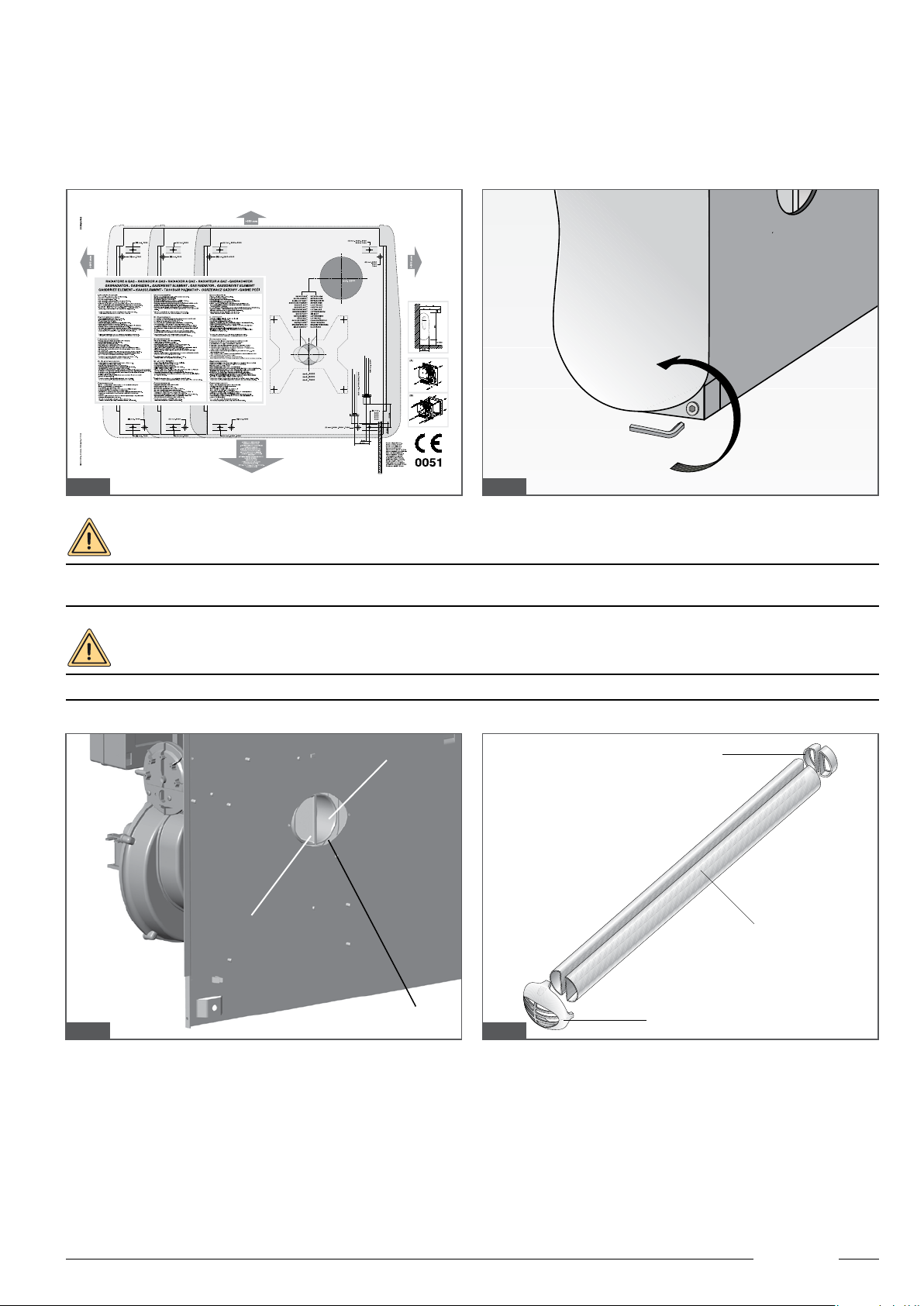
4.2 Installation
Equipment packing includes a paper template: apply it on the wall and use it to drill at the proper points, complying with the minimum
ground clearance.
Prepare the equipment, remove the foam polystyrene protections and carefully separate the painted casing avoiding any damage. To
remove the casing, you must remove the two bottom screws, one on the LH side and one on the RH side, using the spanner supplied.
Remember to tighten them back when operations are completed.
WARNING
Use rock wool, berglass or ceramic up to a thickness of at least 1 cm to insulate intake and vent pipes in order to avoid
condensation, especially if pipes go through walls made of ammable material.
WARNING
With reference to g. 9, intake is on the LH side an vent on the RH side.
C
A
B
D
Intake
Vent
Fig. 8
Fig. 10
Fig. 7
Fig. 9
18
4.2.1 Straight wall vent
For instructions on how to install the straight wall vent also refer to paragraph “10. SEQUENCE FOR INSTALLING A STRAIGHT
WALL VENT”.
• Measure wall thickness and cut the supplied pipes to wall size plus 5 cm.
• Install seals Dto pipes Aand insert the latter, thus prepared, into stub pipes Cof the equipment, using sliding agent to help insertion
if necessary (see gures 10 and 11). Make sure that seals are properly in place and do not obstruct air or ue gas passage.
• Fasten equipment to the wall by means of the supplied screws and anchors.
• If equipment is installed under a shelf or windowsill made from ammable material, protect its lower part using a sheet of
insulating material.
• If equipment is installed under a windowsill (usually made from marble), it is always advisable to insulate its lower face to
minimise heat dispersion to the outside.
• Fasten intake and vent terminal Bto the external wall using the supplied screws, avoiding to cement the pipe in order to allow
equipment removal in the future, if necessary. Close any gaps with rock wool.
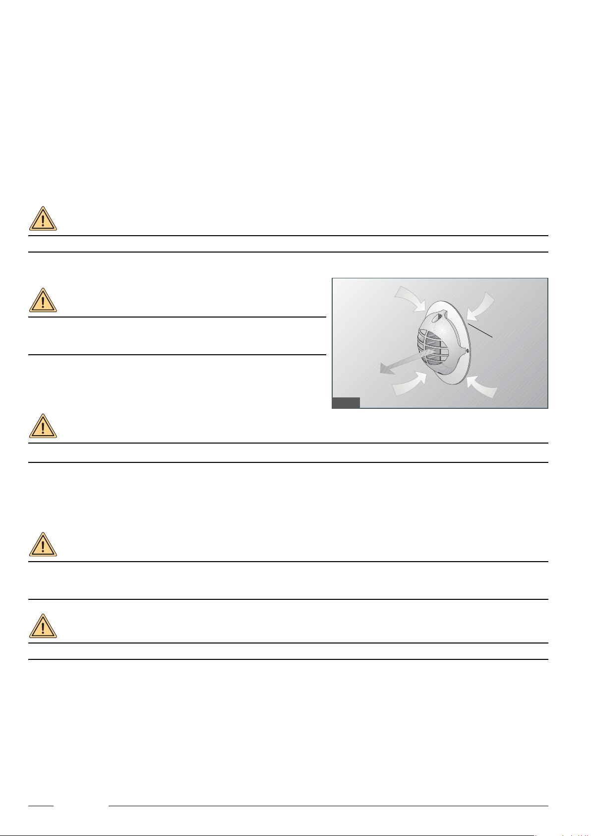
WARNING
It is compulsory to fasten the intake and vent terminals to the external wall in a secure manner.
WARNING
The air necessary for combustion is taken in through the slits on the
external wall (g.11), which should hence be free: avoid cementing or
using sealants of any kind.
It is always preferable to install the supplied stainless steel disc (A)
(g.11).
WARNING
Pipes must be slightly slanted downwards to allow drainage of any condensation.
4.2.2 Vent pipe with extensions or elbows
Gazelle EVO allows the use of extensions and elbows for intake and vent pipes.
This allows for a wide range of solutions to overcome installation issues connected with the impossibility of direct venting.
35 mm and 60 mm diameter pipes are available.
WARNING
Condensation occurs more easily when using pipe extensions. To prevent it from entering the heat exchanger, always
use the suitable accessories for draining condensate.
Condensate draining accessories must be connected to a trap having a head of at least 10 cm.
WARNING
Insulate the vent pipes!
A
Fig. 11

19
V
R
R
The gures 13 A / B show a few examples:
To extend the vent, the splitter kit can be used with support bracket, or the pipes can be connected directly to the equipment. In this
latter case, follow this procedure:
• Install seal Don adapter F (g.13 A).
• Use sliding agent if necessary to engage adapter Finto stub pipe C (g. 9) and fasten it to equipment base with screw Y(supplied)
(g. 13C).
• Insert pipe Ø 35 mm or 90° elbow into adapter, putting the relevant seal G in-between, to be tted in the coupling of the elbow or
pipe (g. 13 B).
• Elbows Ishall be fastened to the base by means of the suitable brackets S supplied in the splitter KIT (g 13 C).
• To join an elbow to a pipe or put two pipes together, engage and cover them with the seal H (g.13 B).
• Insert terminal Lon the pipe, pulling the relevant closing screw V. Intake and vent terminals are the same. If 35 mm pipes run
parallel, use the standard intake/vent terminal (g.14 A).
When splitting pipes, they can be installed recessed in the wall or onto the walls.
If pipes must be installed along the walls, the suitable spacer support supplied as accessory can be used (g.15)
F
D
GFD
H
I
I
I
S
S
Y
Fig. 12A
Fig. 13A
Fig. 13B
Fig. 13CFig. 12B
Fig. 14A Fig. 14B Fig. 15
WARNING
Do NOT install the air diaphragm provided in the kits (R in g.14 A and 14 B).
Note: lay vent above intake.

20
When using the supporting brackets, with the relevant kit (accessory), it is possible to install the equipment after laying down the pipes
(all information necessary for installation is attached to the kit).
Here below are some examples for this application:
Front view
Fig. 16A
Rear view
Fig. 16C
Ø 60
W
Ø 35 mm
mm
Fig. 17
4.2.3 Roof vent
When using the roof vent, the accessory (diameter 60 mm) must be used as a vent terminal.
The nal pipe must then be diameter 60 mm: if the pipes used are 35 mm, it will be necessary to use the adapter W 35/60, available
as an accessory (Fig. 18).
Rear view
Fig. 16B
This manual suits for next models
3
Table of contents
Popular Convection Oven manuals by other brands

Belshaw Brothers
Belshaw Brothers Truebake 35E Installation and operation manual

Inoksan
Inoksan FKG022E instruction manual

Blodgett
Blodgett SC-10DS Specifications

Rosewill
Rosewill R-HCO-15001 user manual

Zanussi
Zanussi EasyPlus 10 GN 2/1 Brochure & specs

Garbin
Garbin PICCOLO INSTRUCTIONS FOR THE INSTALLATION, USE AND MAINTENANCE


