Belshaw Brothers Truebake 35E User manual

233228 - 1
Installation and Operation Manual
6-Pan Convection Oven, Electric
Model Nbr: BACO35E

The reproduction or copying of any part of this manual by any means whatsoever is strictly forbidden unless authorized previously in
writing by the manufacturer.
In line with policy to continually develop and improve its products, Belshaw Adamatic, reserves the right to change the specifications
and design without prior notice.
© Copyright Belshaw Adamatic. April 2009

US/Canada/Mexico Limited Warranty and Return Policy
Belshaw Adamatic Bakery Group warrants parts of its manufacture and assembly of equipment to be free
from defects in workmanship and material which would result in product failure under normal use and
service. Belshaw Adamatic Bakery Group’s entire liability under this Warranty is limited to either repairing
or replacing at its factory or; on user’s premises, at Belshaw Adamatic Bakery Group’s option, any
equipment or parts thereof, which shall be determined by Belshaw Adamatic Bakery Group to be defective.
If necessary to return parts to the factory they must be shipped transportation charges prepaid. This
shall be purchaser’s sole and exclusive remedy.
Belshaw Adamatic Bakery Group reserves the right to make changes in design, or add any improvement, at
any time without incurring any obligations to install the same, on equipment previously sold.
This warranty is expressly in lieu of any and all other warranties express or implied, including:
implied warranties of merchantability and fitness for any particular purpose, and all other
obligations or liabilities what so ever on Belshaw Adamatic Bakery Group’s part. All statutory
or implied warranties, other than title, are expressly nullified and excluded.
Belshaw Adamatic Bakery Group neither assumes nor authorizes any person to assume for it
any obligation or liability in connection with the sale of its products or parts thereof.
Possession, use/or operation of equipment, or parts sold hereunder for any other than their designed
purpose, or use of equipment which is in poor repair, modified, improperly operated, or neglected is done
at the owner’s risk. Belshaw Adamatic Bakery Group hereby disclaims any liability for these actions and
shall not be liable for defects in or for any damages or loss to the property sold which is attributable to
such actions.
Under no circumstances shall Belshaw Adamatic Bakery Group be liable for any indirect,
special, incidental, or consequential damages arising out of, or from the use of Belshaw
Adamatic Bakery Group’s product by buyer, it assignees, employees, agents or customers.
Belshaw Adamatic Bakery Group makes no express warranties except those contained in this Warranty
concerning the product sold hereunder. No modification or alteration of this Warranty shall be made
except by Belshaw Adamatic Bakery Group in writing.
Warranty Period / Guidelines
This limited warranty shall extend for a period of one year from date of shipment and to the original owner
only. It covers parts (manufactured by Belshaw Adamatic Bakery Group) and labor. This warranty covers
only items sold within the United States, Canada and Mexico. A pre-authorization must be obtained from
Belshaw Adamatic Bakery Group before any warranty work is carried out, failure to do so may void the
warranty of the product.
Belshaw Adamatic Bakery Group www.belshaw-adamatic.com Phone (206) 322-5474 Fax: (206) 322-5425
Revised 03/10/2007 US / Canada / Mexico Limited Warranty Page 1 of 2

Belshaw Adamatic Bakery Group www.belshaw-adamatic.com Phone (206) 322-5474 Fax: (206) 322-5425
Revised 03/10/2007 US / Canada / Mexico Limited Warranty Page 2 of 2
Limited Warranty
With respect to parts not manufactured by Belshaw Adamatic Bakery Group, warranty coverage shall be
limited to the original part manufacturer’s warranty, or the Belshaw Adamatic Bakery Group limited
warranty, whichever is the lesser coverage period. In no case will the warranty be in excess of 18 months
after date of shipment of the equipment.
Replacement parts provided under the terms of this warranty are warranted for the remainder of the
original warranty period applicable to the product.
Exclusions:
This warranty excludes from its coverage and does not apply to: (a) solenoid and relay coils; (b) lamps;
(c) “O” rings; (d) belts; and (e) impellers. These items are excluded because (1) failure is usually due to
causes beyond our control; (2) it is not practical to accurately determine the failure cause; and (3) the
normal life of the parts is shorter than our warranty period.
Procedure for Return:
To speed up your credits for returned equipment, we have a return goods policy and procedure. Our
procedure starts with a phone call to (206) 322-5474 or Service Department for a return authorization.
When contacting Service Dept. you should be ready to give:
• Customer name, address, phone number and individual’s name, Invoice number and date, Model
number and serial number, reason for return (i.e. credit, exchange, warranty, or repair), description
of item, and problem.
When we get this information we will issue you a Return of Goods Authorization Number (RGA). This
number must be marked clearly on the outside of the package. If the package is not clearly marked with
the RGA#, then the package will be returned unopened to the sender. The RGA# will be open for 30 days,
if returnable goods have not been received within the 30 days, then RGA# will be voided.
Return goods must be:
• Returned freight prepaid, packaged securely and carefully so that in-transit damage cannot occur.
• Marked so the package contains the RGA# in the first line of the address line, “Attn: RGA#” (the
number being the number given you by the Belshaw Adamatic Bakery Group service department.)
Please note the following:
• If the returned goods were sent to you due to our mistake, then we will pay all freight charges via
our choice of carrier.
• If the returned goods failed while in service and are still covered by warranty, they need to be
returned freight prepaid by you. We will then replace the goods at no charge.
• When returning parts for re-stock: our minimum re-stocking charge is 20% of original invoice
amount or $20 (whichever is greater), providing the equipment is in new, never-been-used
condition. Restocking charges may be increased above the minimum, depending on how much
rework the returned goods need. Final determination will be made after factory inspection of goods.
• No RGA# will be issued if the item in question was invoiced anytime prior to 180 days of the request.
Following these guidelines will help expedite the processing of your return.

Contents
BACO35E Convection Oven
Introduction ........................................................................................... 2
Specifications ......................................................................................... 3
Installation ............................................................................................. 4
Installation Requirements
Before Connection to Power Supply
Location
Bench Mounting
Floor Mounting
Stand Mounting
Electrical Connection
Water Connection
Before Use
Operation................................................................................................ 6
Description of Controls
Baking
Door Handle
Oven Side Racks
Removal of Side Racks
Replacement of Side Racks
Cleaning................................................................................................ 10
Cleaning Guidelines
Exterior
Interior
Oven Racks
Side Racks
Oven Door Glass
Oven Door Seal
Faultfinding .......................................................................................... 11
Wiring Schematic ................................................................................. 12
BACO35E Circuit Schematic
BACO35E Wiring Diagram
Replacement Parts List......................................................................... 14
Date Purchased .......................................................... Serial No.......................................................
Dealer.............................................................................................................................................
Service Agent ..................................................................................................................................

2
Introduction
We are confident that you will be delighted with your
Truebake 35E Convection Oven
, and it will
become a most valued appliance in your commercial kitchen.
A new oven can seem very complex and confusing at first glance. To ensure you receive the utmost
benefit from your new
Truebake 35E Convection Oven
, there are two important things you can do.
Firstly
Please read the instruction book carefully and follow the directions given. The time taken will be well
spent.
Secondly
If you are unsure of any aspect of the installation, instructions or performance of your oven, contact your
Belshaw Adamatic dealer promptly. In many cases a phone call could answer your question.

3
Specifications
ELECTRICAL ENTRY
283
8"
PLAN
FRONT
345
8"
31
8"
311
2"
61
2"
261
4"
SIDE
25
8"
17
8"
345
8"
61
2"
WATER ENTRY
VENT Ø 76 O.D.
247
8"
E
MWS
3
MWS
E
3
E
3
MWS
Electrical Connection Refer to Section 'Before Connection to Power Supply' on Page 6.
Cold Water Connection ¾” B.S.P. or 1/2ID hose (550kPa / 80psi maximum pressure).
15/16”
BACO 35E Specifications

4
Installation
Before Connection to Power Supply
• Remove all packing.
• Check equipment and parts for damage. Report any damage immediately to the carrier and
distributor.
• Remove protective plastic coating from the side panels.
• Check that the following parts have been supplied with your oven:
1 x Water inlet elbow (c/w washer).
• Report any deficiencies to the distributor who supplied the oven.
• Fit the feet to the oven.
• Check that the available power supply is correct to that shown on the rating plate located on the
right-hand side panel.
Location
• To ensure correct ventilation for the motor and controls the following minimum installation
clearances are to be adhered to:
• Position the oven in its working position.
• Use a spirit level to ensure oven is level from side to side and front to back. (If this is not carried
out, uneven cooking could occur). The feet / legs used with bench / floor mounting or provided
with stands are adjustable and will require adjusting in levelling the unit.
• The unit should be positioned such that the operating panel and oven shelves are easily
reachable for loading and unloading.
Installation Requirements
It is most important that this oven is installed correctly and that operation is correct
before use.
Installation shall comply with local electrical, health and safety requirements.
This equipment is to be installed to comply with the Federal, State or local plumbing
codes having jurisdiction.
Rear 0“ / 0 mm
Left-hand side 0” / 0 mm
Right-hand side 3” / 75 mm (Fixed installations require at least 500mm (20”) clearance at
the right hand side for service accessibility).
Model Electrical Rating
BACO35E208-3 208 V a.c., 60 Hz, 3P+E, 11.2 kW @ 208 V
BACO35E240-3 220-240 V a.c., 60 Hz, 3P+E, 12.5 kW @ 240 V
Important:
THE VENT LOCATED ON THE OVEN TOP MUST NEVER BE OBSTRUCTED.

5
Installation
Bench Mounting
• For bench mounted applications the oven must be fitted with 100mm / 4” feet.
Floor Mounting
• For floor mounted applications the oven must be fitted with 150mm / 6” legs.
NOTE: Four 100 mm / 4” adjustable or 150mm / 6” legs are available separately from your
Truebake 35E dealer as an optional extra.
Stand Mounting
• Ovens that are to be mounted on stands do not require feet or legs. Refer to instructions for
mounting on stand in instructions supplied with separately ordered stands.
• Avoid having heat producing equipment such as fryers or steamers adjacent to the right-hand side
of oven.
Electrical Connection
• Remove side cover panel to allow access to the terminal block and strain relief cable clamp.
• The cable can be fitted through the entry grommet and secured from strain by tightening the fitted
strain relief bushing.
• Connect cable to the terminals as marked.
• Refit cover panel.
THIS APPLIANCE MUST BE EARTHED / GROUNDED.
Water Connection
• A cold water supply should be fitted to the water inlet (¾” BSP connection) which is located near
the rear of the right hand side of the unit.
• Alternately, a connection elbow and sealing washer is supplied with this unit for direct connection
of a ½” ID hose, and is recommended for easy installation and service.
• Connect water supply - Max inlet pressure 80 psi / 550 kPa.
• Turn on water supply to check for leaks.
Before Use
• Operate the oven for about 1 hour at 400°F (200°C) to remove any fumes or odours which may be
present.
Important:
• FIXED WIRING INSTALLATIONS MUST INCORPORATE AN ALL-POLE DISCONNECTION SWITCH.
C
AUTION
:
To reduce the risk of fire, the appliance is to be installed over a non-combustible surface
only. Such surface shall extend not less than 12 inches (300mm) beyond the appliance on all
sides.
6
Operation
°C
60
80
100
120
140
160
180
200
220
280
l
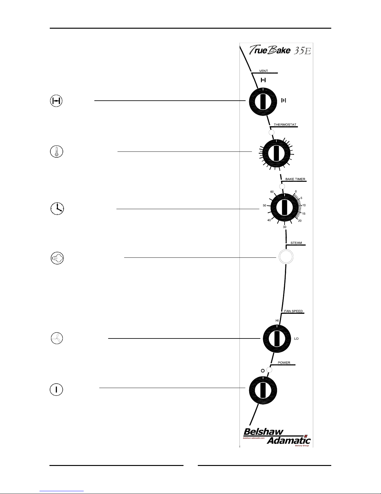
Vent
Vent closed with switch in the vertical position.
Vent open with switch in the horizontal position.
Thermostat
Temperature range 100 - 550°F (60-280°C).
Indicator illuminates when the elements are cycling
ON to maintain set temperature.
Bake Timer
1 Hour bake timer.
(Indicator illuminates when “time up” (0) reached,
and buzzer sounds).
Steam Switch
Push steam switch to activate steam into the oven
chamber. Release switch to stop steam.
Fan Speed
Full fan speed in the vertical (HI) position.
Half fan speed in the horizontal (LO) position.
Power
Turn to switch power on or off (on horizontal, off
vertical) (indicator illuminates when power is on).
Description
of
Controls

7
Operation
Baking
1. Turn Power 'On'
The indicator light will illuminate whenever the switch is in the “I” (on) position (the oven
lights will also illuminate).
The oven fan will start when the door is closed.
The oven fan will change rotation direction every 90 seconds.
2. Fan Speed
The oven fan can either be operated at “HI” fan speed or “LO” speed by rotating the knob.
This maybe done before or during a cooking cycle.
For most applications the HI fan speed provides best results. For delicate baked products or
roasting the LO fan speed may be more suitable.
3. Oven Vent
The oven vent can be opened or closed at any stage during a cooking cycle in the oven.
For best steam results on baked product always ensure the oven vent is closed.
The oven vent combines an over pressure feature that allows the vent to open automatically
when required for periods when steam injection is used, to relieve excess pressure.
4. Set Thermostat to Desired Cooking Temperature
The thermostat indicator light will illuminate when ever the elements are cycled on to maintain
set temperature.
5. Load Oven
Once the oven is up to temperature, open the door and load the oven with product. Avoid
delays in loading the oven with the door open as this will delay oven temperature recovery.
The ovens fan will stop when the door is opened. The fan will restart after the door is closed.
6. Steam
When steam is required press the steam button. Steam will be injected into the oven chamber
for as long as the steam button is held pressed.
7. Set Timer to Desired Time.
To set timer, turn knob clockwise to the required time. At any stage, the time can be adjusted
in either direction.
For settings less than 10 minutes, first set to greater setting, then turn down to required time
period.
This 60 minute timer is completely independent of the oven control.

8
Operation
8. Time Up
When the timer reaches 0 minutes the buzzer will sound, and the indicator illuminates.
To cancel the buzzer turn the timer to the off position.
9. Unload Oven
Open the door and unload the oven .
The oven fan will stop when the door is opened.
Door Handle
Standard Door Catch Operation
A. To open the oven door, rotate the handle either clockwise or anti-clockwise to the 'Open'
position to unlatch the door and pull the door open with the door handle.
B. To close the door, push the door firmly closed and the door will lock in the closed position.
(there is no need to turn the handle to the closed position as the door self-latches in the
closed position and the handle will self-centre to the 'Closed' position.
Open
Open
Closed

9
Operation
Side Racks
1. The side racks can be fitted in one of two
positions, in order to take 16 or 18 inch
trays.
2. To position racks for 16 inch trays, use the
holes at the rear of the rack.
3. Alternatively for 18 inch trays, use the holes
nearest the centre of the oven.
Removal of Side Racks
1. Lift the side rack off the bottom locating
pins.
2. Move the bottom of the side rack toward the
centre of the oven.
3. Lower side rack to clear top locating pins,
and remove.
Replacement of Side Racks
1. Insert rack into the oven, placing
appropriate holes over the top locating pins.
2. Lift the side rack over the bottom locating
pins.
3. Lower side rack with the appropriate holes
over the bottom locating pins.
16 inch
tray locator
18 inch tray
locator
1
3
2
10
Cleaning
Exterior
Clean with a good quality stainless steel cleaning compound. Harsh abrasive cleaners may damage
the surface.
Interior
Ensure that the oven chamber is cool. Do not use wire brushes, steel wool or other abrasive materials.
Clean the oven regularly with a good quality oven cleaner. Take care not to damage the fan or oven
lights.
Oven Racks
To remove the oven racks, follow instructions given in the Operation section.
Side Racks
To remove the side racks, follow instructions given in the ‘Operation’ section.
Cleaning Guidelines
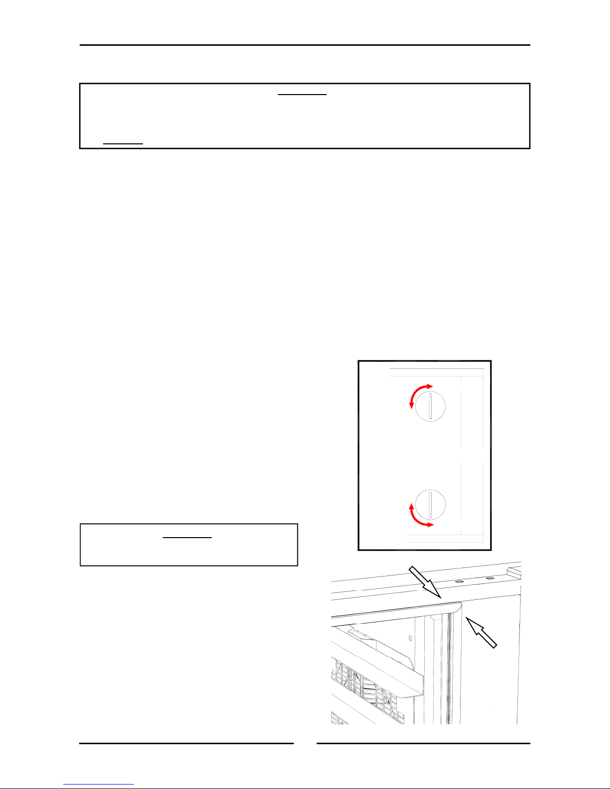
Oven Door Glass
Outer Surfaces
Clean with conventional glass cleaners.
Inner Surfaces
To clean between the inner and outer door
glasses, firstly ensure the door is locked shut
(refer to page 10). With a screwdriver, coin, or
other suitable device, turn the outer glass locks
a ¼ turn to release the outer glass and allow it
to be hinged open for cleaning access (refer to
diagram opposite for correct procedure).
Oven Door Seal
To remove, pull out the seal starting at each
corner.
The seal may be washed in the sink, but take
care not to cut or damage it.
To replace, fit the seal in at the corners first,
then push in the rest of the seal.
LOCKED
BOTTOM
UN-LOCKED
UN-LOCKED
LOCKED
Important:
Always ensure outer glass is hinged closed and
locked into position before opening the oven door.
TOP
C
AUTION
:
Always turn off the electrical supply at the mains supply before cleaning.
This appliance is not water proof.
Do not use water jet spray to clean interior or exterior of this appliance.

11
Fault Finding
Fault Possible Cause Remedy
The oven does not operate /
start.
The mains isolating switch on the
wall, circuit breaker or fuses are
'Off' at the power board.
The power switch on the oven is
'Off'.
Overtemp safety thermostat
tripped.
Turn 'On'.
Depress switch. Switch will
illuminate.
Reset (Button located at bottom
RH side of RH side panel). If fault
re-occurs call for service.
Bake timer does not time down. Bake timer not set correctly. For settings less than 10 minutes,
first set to greater setting then turn
back to desired setting.
Oven light not illuminating. Blown bulb. Replace bulb.
No water injection / steam. Water not turned 'On'. Turn water 'On' at water supply.
Oven light illuminating but fan
not working and oven not heat-
ing.
Oven door not closed properly.
Door switch or door catch broken.
Close oven door properly.
Call for service.
This section provides an easy reference guide to the more common problems that may occur during the
operation of your equipment. The fault finding guide in this section is intended to help you correct, or at
least accurately diagnose problems with your equipment.
Although this section covers the most common problems reported, you may encounter a problem not
covered in this section. In such instances, please contact your local authorised service agent who will
make every effort to help you identify and resolve the problem. Please note that the service agent will
require the following information:-
• Model code and Serial Number of the appliance. (both can be found on the Rating
Plate located on the appliance.

12
Wiring Schematic
BACO35E - Wiring Schematic, 208 - 240V, 3P+E
13
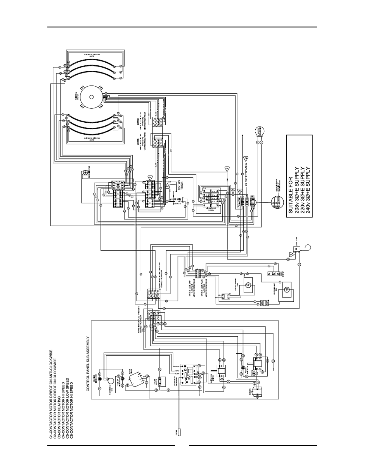
Wiring Schematic
BACO35E - Wiring Diagram, 208 - 240V, 3P+E

14
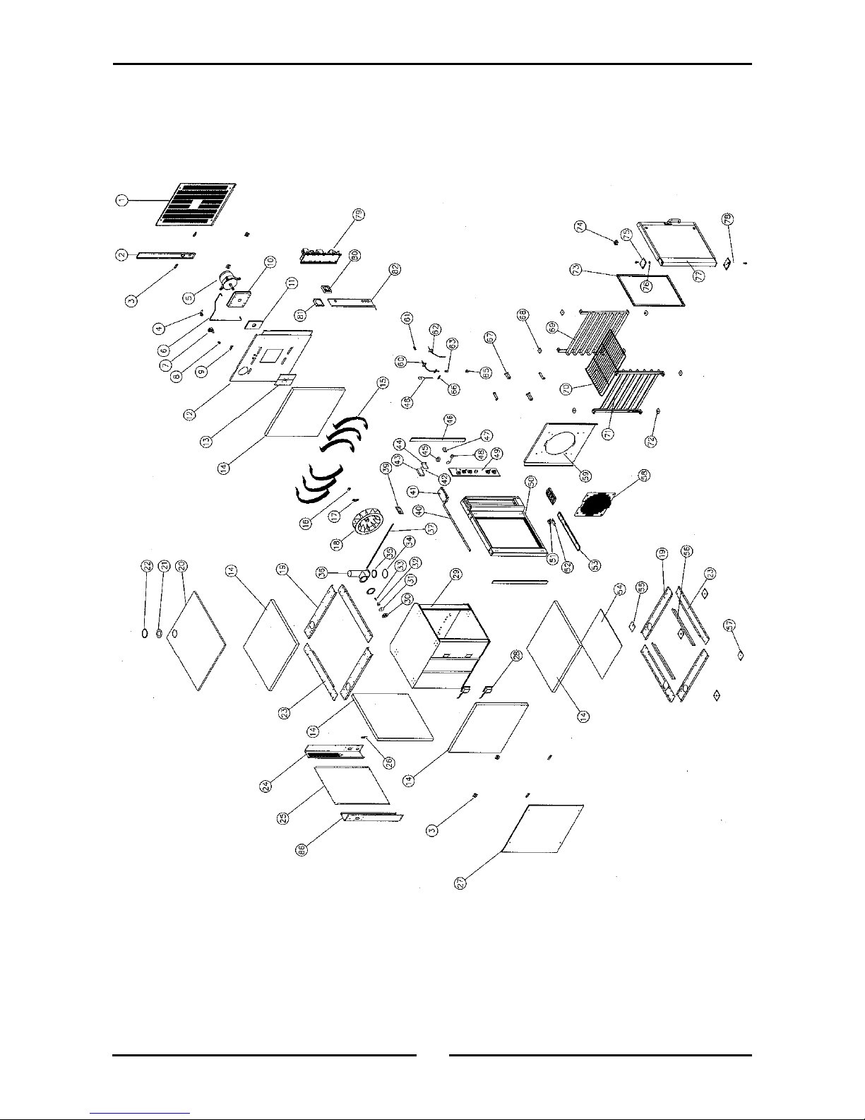
Replacement Parts List
Main Assembly Parts List - BACO35E
Pos Part No. Description
1 023971 SIDE PANEL RH.
023972 SIDE PANEL RH.
2 020792 SERVICE ENTRY PANEL.
3 020785 PANEL MOUNTING BRACKET.
4 021526 WATER INLET ELBOW.
021527 WATER INLET WASHER.
5 020886K MOTOR (208-240V 60Hz).
025751 FAN MOTOR HEAT FLINGER.
6 020860 WATER SUPPLY TUBE.
7 020851 WATER SOLENOID.
8 020869 CONNECTOR - 3/8"F x 1/4" COMPRESSION.
9 020991 MOUNTING BRACKET.
10 020897 MOTOR INSULATION PLATE.
11 020778 MOTOR MOUNTING PLATE.
12 231798 SIDE INSULATION PANEL.
13 021160 OVEN SIDE PLATE.
14 090416 FIBREGLASS INSULATION 730x780x38.
15 020763 ELEMENT - 208-220V 2000W (P,X only).
015292 SEALING WASHER.
16 020896 MOTOR SHAFT SEAL.
17 020898 MOTOR SEAL HOUSING.
18 025396 FAN.
19 020780 CHASSIS HORIZONTAL SIDE.
20 020795 TOP COVER.
21 022425 VENT SEAL.
22 022426 VENT SEAL FLANGE PLATE.
23 020781 CHASSIS HORIZONTAL.
24 023970 CHASSIS VERTICAL REAR RH.
25 020791 BACK PANEL.
26 020895 CABLE GUIDE BRACKET.
27 020787 SIDE PANEL LH.
28 232108 OVEN LAMP HOLDER & BULB.
021352 OVEN LAMP - GLASS LENS.
021354 OVEN LAMP - GASKET.
231814 OVEN LAMP BULB G9/25W.
021353 OVEN LAMP -SUPPORT FRAME.
29 004703 OVEN WA - ENAMELLED.
30 020828 VENT FLAP.
Replacement Parts List
When ordering replacement parts, please quote the part number and the description as listed below. If the
part required is not listed below, request the part by description and quote model number and serial
number which is shown on the rating plate.
IMPORTANT:
Only genuine authorized replacement parts should be used for the servicing and
repair of this appliance. The instructions supplied with the parts should be followed
when replacing components.
For further information and servicing instructions, contact your nearest authorized
service branch (contact details are as shown on the reverse of the front cover of this
manual).

15
Replacement Parts List
Pos Part No. Description
31 020827 VENT OVER PRESSURE PLATE.
32 020819 OVER PRESSURE SPRING.
33 041425 SCREW - M4 x 6 PAN POZI.
34 016241 VENT HOOD.
35 020824 VENT GASKET.
36 020845 VENT WA.
39 231789 VENT SWITCH BRACKET.
40 020761 TOP BUTT STRAP.
41 020764 CONTROL HOUSING CAP.
020865 SCREW CAP - BLACK.
42 018768 STAND-OFF.
43 020882K THERMOSTAT - SOLID STATE.
44 020775 THERMOSTAT BOARD MOUNTING BRACKET.
45 011794 BUZZER.
46 020783 CHASSIS VERTICAL FRONT.
47 014032 BUZZER MOUNTING BRACKET.
48 019369K OVERTEMP THERMOSTAT KIT.
013506 GLAND WASHER.
013507 GLAND BUSH.
013508 GLAND NUT.
020887 SPLIT GLAND NUT ASSY (c/w Split nut, Seal & Washer).
020892 GLAND BUSH MOUNTING PLATE.
49 233239 CONTROL PANEL ASSEMBLY (Refer Page 17).
50 232080 FACIA WA.
51 020774 MICROSWITCH.
52 020829 MICROSWITCH MOUNTING BRACKET.
53 232217 MICROSWITCH COVER PANEL.
54 020793 BASE COVER SHEET.
55 020899 BLANKING PLATE.
56 020784 OVEN SUPPORT BRACKET.
57 230577 LEG PLATE.
58 020881 FAN GUARD.
59 020879 FAN BAFFLE.
60 020857 STEAM TUBE WA.
61 020861 COMPRESSION UNION ¼".
62 020883K PROBE KIT.
020856 GASKET.
63 016794 MALE CONNECTOR.
65 020853 SPRAY BODY - WHIRLJET.
020856 GASKET.
66 020890 PROBE SECURING BRACKET.
67 020844 BAFFLE SPACER WA.
68 020802 RACK LOCATION UPPER WA.
69 020810 SIDE RACK RH WA.
70 015168 OVEN RACK.
71 020809 SIDE RACK LH WA.
72 020803 RACK LOCATION LOWER WA.
73 231438 DOOR SEAL.
74 020754 BOLT CATCH.
75 023050 HINGE MOUNTING PLATE TOP.
020876 TOP HINGE BOLT.
76 020738 HINGE BUSH.
77 232103 DOOR ASSEMBLY (Refer Page 20).
78 230741 HINGE MOUNTING PLATE TOP.
230742 HINGE MOUNTING PLATE BOTTOM.
79 233387 GEAR PLATE (Refer Page 18).
80 021156 COOLING FAN.
81 021157 COOLING FAN BRACKET.
82 231784 HEAT BAFFLE.
86 020782 CHASSIS VERTICAL REAR LH.
Main Assembly Parts List (Cont’d) - BACO35E
16
Replacement Parts List
Main Assembly - BACO35E
This manual suits for next models
1
Table of contents
Other Belshaw Brothers Convection Oven manuals

Belshaw Brothers
Belshaw Brothers BX Classic 10-Tray User manual

Belshaw Brothers
Belshaw Brothers True Bake 32G User manual

Belshaw Brothers
Belshaw Brothers BXC Smartbake User manual

Belshaw Brothers
Belshaw Brothers Adamatic BX10-C Operating and safety instructions

Belshaw Brothers
Belshaw Brothers BACO25E User manual

Belshaw Brothers
Belshaw Brothers BX4-C User manual


