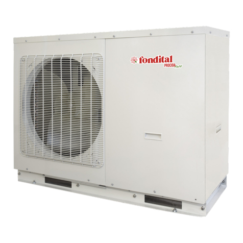
Fondital PROCIDA AWS X4 User manual

IST 03 J 048 - 02
PROCIDA AWS
X4 - X6 - X8 - X10
INSTALLATION MANUAL
SPLIT AIR/ WATER HEAT PUMP
EN
Translation of the
original instructions
(in Italian)
Thank you for choosing a heat pump by Fondital. Carefully read this Manual before using
the unit and keep it for future reference.

2
For users
Thank you for choosing a product by Fondital. In order to use the product correctly, please carefully read this instruction manual before
installation and use. To achieve the intended operation of the air conditioner, please follow the recommendations below for the proper
installation and use of the product:
1. Installation, use and maintenance of this appliance must be carried out by specially trained technical personnel. During operation,
the safety instructions on labels, in the User manual and other documents must be strictly complied with. The appliance can be
used by children aged 8 years and over and by persons with physical, sensory and cognitive impairments, or lacking appropriate
experience and knowledge provided that they are supervised or have been instructed in the safe use of the appliance and under-
stood the associated dangers. Do not allow children to play with the appliance. Cleaning and maintenance must not be carried
out by children without proper supervision.
2. This product underwent a strict inspection and operating tests before leaving the factory. In order to avoid damage due to improp-
er disassembly and inspection, which could aect the normal operation of the unit, do not disassemble it yourself. If necessary,
contact our company's authorised service centre.
3. Our company shall not be liable for personal injury, loss or damage to property caused by improper use, including improper in-
stallation and debugging procedures, unnecessary maintenance, violation of applicable national laws, regulations and industry
standards, and failure to follow this instruction manual.
4. If the product is faulty and can not be used, please contact our service centre as soon as possible and provide the following
details.
» Contents of the product nameplate: product code, model, cooling/heating capacity, serial number, date of manufacture (Man-
ufactured Date).
» Malfunction condition (specify the situations before and after the error is displayed).
5. All drawings and data in this instruction manual are provided for reference only. The product is subject to continuous improve-
ments and innovations aimed at optimising its quality. We reserve the right to make any necessary changes to the product at any
time for commercial or production reasons, as well as to revise the contents of the manual without prior notice.

3
1. Diagram of the operating principle ............................................ 11
2. HEATING AND COOLING AND DHW WITH CIRCUIT BREAKER ...................12
3. Unit operating principle .....................................................14
4. Name ..................................................................16
5. Installation example .......................................................17
6. Key components ..........................................................20
6.1 Indoor unit ............................................................................................................................................................ 20
6.2 Outdoor unit.......................................................................................................................................................... 22
7. Guidelines for outdoor unit installation .........................................23
7.1 Instructions for the installation.............................................................................................................................. 24
7.2 Outdoor unit installation........................................................................................................................................ 24
8. Indoor unit installation ...................................................... 26
8.1 Choosing the position for indoor unit installation.................................................................................................. 26
8.2 Clearances to be observed when installing the indoor unit (mm)......................................................................... 27
8.3 Indoor unit external dimensions ........................................................................................................................... 28
8.4 Precautions for indoor unit installation ................................................................................................................. 28
8.5 Water volume and pump capacity........................................................................................................................ 28
8.6 Water volume and pressure in the expansion tank .............................................................................................. 29
8.7 Selecting the expansion tank ............................................................................................................................... 29
9. Piping connection .........................................................30
9.1 Connecting the outlet pipe for indoor unit and outdoor unit.................................................................................. 30
9.2 Applying a protection layer to the connecting pipe............................................................................................... 30
10. Remote ambient temperature sensor ..........................................32
11. Thermostat ..............................................................33
12. 2-way valve ..............................................................33
13. 3-way valve ..............................................................34
14. Other auxiliary heat sources .................................................35
15. Door control unit ..........................................................36
16. Refrigerant lling and draining ...............................................36
17. Collecting refrigerant.......................................................37
18. Unit handling .............................................................37
19. Installing a sealed storage tank ..............................................38
19.1 Installation sizes................................................................................................................................................... 38
19.2 Connection of the hydraulic system ..................................................................................................................... 39
19.3 Electrical connection ............................................................................................................................................ 39
20. Wiring diagram ...........................................................41
20.1 Control board (Indoor unit) ................................................................................................................................... 41
20.2 Electrical connections........................................................................................................................................... 47
21. Commissioning ...........................................................55
21.1 Checks before start-up......................................................................................................................................... 55
21.2 Operation test....................................................................................................................................................... 56
22. Operation and routine maintenance ...........................................57
22.1 Recovery .............................................................................................................................................................. 59
22.2 Decommissioning................................................................................................................................................. 59
22.3 Safety notes ......................................................................................................................................................... 60
22.4 Precautions before seasonal use......................................................................................................................... 61

4
Safety warnings (to be strictly adhered to)
WARNING: failure to follow these instructions could result in serious damage to the unit or injury to persons.
NOTE: failure to follow these instructions could result in minor or moderate damage to the unit or injury to persons.
This sign indicates that operation must be prohibited. Incorrect operation may cause serious damage or be life-threatening.
This signal pinpoints some conditions that must be complied with. Incorrect operation can cause damage to people or
property.
NOTE
Upon receipt of the unit, check its appearance, verify the model and parts supplied, and ensure that everything is as ordered.
The design and installation of the unit must be carried out by authorised personnel, in accordance with current laws and regulations
and with these instructions.
After installation, the unit may only be put into operation if there are no problems to check.
After normal use, carry out the specied periodic cleaning and maintenance procedures to ensure trouble-free operation and long life
of the unit.
If the power cable is damaged, it must be replaced by the manufacturer, its service agent or similarly qualied persons in order to
avoid danger.
The unit must be installed in accordance with national wiring regulations.
This product is a general-purpose air conditioner and must not be installed in the presence of corrosive, explosive, ammable or pol-
luting substances because use under such conditions would cause malfunctions, a shorter service life, re hazard and risk of serious
injury to persons. Special air conditioners must be used under the above-mentioned conditions.
This marking means that the product must not be disposed of as household waste in EU countries. Recycle the prod-
uct with a sense of responsibility to promote sustainable reuse of resources and avoid any damage to the environment
or human health resulting from uncontrolled disposal of waste. To return the used appliance, rely on sorted waste
systems or contact the dealer where appliance was purchased. The dealer could take the product and recycle it in an
environment-friendly manner.
R32:675

5
WARNING
In the event of anomalies, such as a smell of something burning, immediate-
ly switch o the unit and contact a service centre.
If the anomaly persists, the unit may be damaged and an electric shock or
re may occur.
Do not operate the unit with wet hands.
Non-compliance could result in an electric shock hazard.
Before installation, check that the mains voltage corresponds to the values
indicated on the unit's rating plate and that the capacity of the electrical sys-
tem, power cable or electrical outlet is compatible with the unit's power re-
quirements.
A special power supply circuit must be used to avoid re hazards.
Do not use multiple sockets or extension cords for connecting the cables.
When the unit is left unused for a long period, unplug it and empty the indoor
unit and the water storage tank.
Non-compliance may result in the dust building up causing a risk of overheat-
ing, re or (in winter) freezing of the storage tank or coaxial heat exchanger.
Do not damage the electrical cable or use a cable that does not comply with
the specications.
Non-compliance may result in overheating or re.

6
Before cleaning the unit, disconnect it from the mains.
Non-compliance could result in risk of an electric shock or damage to prop-
erty.
The power supply must adopt a special circuit with a residual current circuit
breaker and must have sucient capacity.
The user may not replace the power cable socket without the manufacturer's
prior consent. Electrical connections must be carried out by a professional.
Ensure that the unit is properly connected to ground and do not change the
way it is connected to ground.
Ground: the unit must have a reliable ground connection! The ground cable
must be connected to a building protection device.
In the absence of such a device, ask a qualied technician to install one. It
is also recommended not to connect the ground cable to gas pipes, water
pipes, drain pipes or other improper items not approved by a professional
technician.
Do not insert foreign objects into the outdoor unit to avoid risk of damage. Do
not insert your hands into the air outlet of the outdoor unit.
Do not attempt to repair the unit yourself.
Improper repair may cause re or electric shock. For this reason, it is recom-
mended to contact a service centre for repairs.

7
Do not climb on the unit or place objects on it.
This could create a falling hazard for people and objects.
Do not obstruct the air inlet and outlet areas of the unit.
Obstructions could reduce eciency or cause the unit to shut down or create
a re hazard.
Keep pressurised sprays, gas cylinders and other similar objects at least 1
m away from the unit.
Fire or explosion hazards may result.
Check that the installation support is suciently stable.
If it is damaged, there is a risk of the unit falling and injuring persons.
The unit should be installed in a well-ventilated place to reduce energy con-
sumption.
When the storage tank and system circuit are empty, the unit must not be
operated.

8
WARNING
Do not use any means other than those recommended by the manufacturer to speed up the defrosting process or for cleaning. If a
repair is necessary, contact the nearest authorised service centre. Repairs carried out by unqualied personnel could be dangerous.
The outdoor unit must be stored in a room free of continuously operating ignition sources (e.g. open ames, gas appliances or elec-
tric heaters in operation). Do not pierce or burn. It contains slightly ammable R32 gas. For repairs, strictly follow the manufacturer's
instructions. Note that refrigerants are odourless. Read the manual for the specic product.
The indoor unit must be located in a well-ventilated room whose dimensions correspond to those specied for operation. It must be
installed, used and stored in a room having an area of at least X m2 (for the measure of space X, refer to table "a" in the section "Safe
use of ammable refrigerants").
If the xed appliance is not equipped with a mains lead with a plug, or other means of disconnection from the mains supply which
ensures a separation between the contacts in each pole and is capable of completely disconnecting the power supply under category
III overvoltage conditions, the instructions state that such a means of disconnection must be incorporated into the xed wiring in ac-
cordance with the regulations in force on electrical connections.
The appliance can be used by children aged 8 years and over and by persons with physical, sensory and cognitive impairments, or
lacking appropriate experience and knowledge provided that they are supervised or have been instructed in the safe use of the appli-
ance and understood the associated dangers. Do not allow children to play with the appliance. Cleaning and maintenance must not
be carried out by children without proper supervision.
The appliance must not be stored in a room containing open ames (e.g. gas appliances) and ignition sources (e.g. electric stoves)
that are continuously in operation.
The appliance must be stored in such a way as to prevent any mechanical damage.
NOTE
The appliance contains slightly ammable R32 gas.
It is recommended to read the user manual before using the appliance.
Read the installation manual before installing the appliance.
Read the service manual before repairing the appliance.

9
The refrigerant used is R32, it is slightly ammable and odourless. It also implies risk of explosion under certain conditions. However,
the ammability of the refrigerant is very low. Ignition is only possible with re. (Open ame)
Compared to commonly used refrigerants, R32 is non-polluting and does not damage the ozone layer. This means that it also has a
lower greenhouse eect. R32 has excellent thermodynamic characteristics that result in very high energy eciency. As a result, the
units require a lower lling level.
Before installation, check that the electrical power ratings at the designated location correspond to the specications on the unit rating
plate and check the reliability and safety of the electrical connection.
The unit must be connected to the mains by means of an unipolar circuit breaker suitable for category III overvoltages.
Before use, check that the electrical cables and water pipes are correctly connected to avoid water leaks, risk of electrocution and
the like.
Do not operate the unit with wet hands. Children must not be allowed to use it.
In the instructions, the on/o switching descriptions refer to the use of the unit on/o button. The power supply is cut by disconnecting
the unit from the mains.
Do not expose the indoor unit directly to the corrosive conditions of environments containing water or humidity.
Do not operate the unit with empty water storage tank. The air outlet/inlet openings of the outdoor unit must not be obstructed by any
objects.
When the unit is not in use, the water in the unit and in the pipes must be drained to prevent the storage tank, pipes and water pump
from cracking due to frost.
Never use sharp objects to press the button. Doing so could damage the manual control unit. Do not use other wires instead of the
special communication line of the unit. Doing so could damage the control elements. Never clean the manual control unit with ben-
zene, thinners or other chemicals to avoid discolouration of the surfaces and damage to the elements. Clean the unit using a cloth
soaked in mild detergent. Gently clean the display screen and connecting parts to avoid discolouration.
The power cable must be separated from the communication line.
Work on the refrigerant circuit must only be carried out by persons with valid certication from an accredited body stating that they can
handle refrigerants safely, in accordance with the specications in force.
Maintenance work on the appliance must be carried out strictly in accordance with the manufacturer's instructions. Maintenance and
repair work requiring the assistance of other qualied personnel must be carried out under the supervision of the person competent
to handle ammable refrigerants.

10
Maximum and minimum water temperatures
Function Minimum water temperature Maximum water temperature
Cooling 7°C 25°C
Central heating 20°C 60°C
Water heating
(tank) 40°C 80°C
Maximum and minimum water pressure values
Function Minimum water pressure Maximum water pressure
Cooling 0.05 MPa 0.25 MPa
Central heating
Water heating
(tank) 0.05 MPa 0.60 MPa
Maximum and minimum water pressure values at inlet.
Function Minimum water pressure at inlet Maximum water pressure at inlet
Cooling
0.05 MPa 0.25 MPa
Central heating
Water heating
(tank)
The external static pressures with which the appliance has been tested are stated (only additional heat pumps and appliances with
additional heaters). If the power cable is damaged, it must be replaced by the manufacturer, its service agent or an equally qualied
person in order to avoid danger.
The appliance is intended to be connected to the water mains permanently and not by means of connecting pipes.
If you have any questions, please contact your local dealer, an authorised service centre, a branch oce or our company directly.

11
Diagram of the operating principle
1. Diagram of the operating principle
Outdoor unit
Ambient temp. sensor
Defrost temp. sensor
Fan
Heat exchanger
with tubes and ns
4-way valve
High pressure sensor
High pressure
switch
Discharge temp.
sensor
Compressor
High pressure switch
(cooling)
High pressure switch
(cooling)
Gas-liquid
separator
Suction temp. sensor
T-economizer inlet
T-economizer uscita
Economizer
Indoor unit
Liquid
pipe T
Water T at
PE outlet
Optional
heating
element
Optional
water
sensor T
Safety
valve
3-way
valve
CH system
ow
DHW
CH system return
Gas pipe T Water T at
PE inlet
Pump Flow switch Expansion
tank
To be made by the installer
3-way
valve
2-way
valve
Mixing
valve
Radiant
temp.
Storage tank temp.
sensor
Storage tank heating element
Storage tank
Thermal
unit
Pump
Notes
(a) Water mixing accessories are provided as an option. If required, please contact the manufacturer.
(b) The 3-way valve to install on site must be controlled by the user.

12 HEATING AND COOLING AND DHW WITH CIRCUIT BREAKER
2. HEATING AND COOLING AND DHW WITH CIRCUIT BREAKER
16
23
6
4
4
69
12
6
13
14
15
13
17
66
18
19
6
20
21
22
A
B
C
1
2
6
6
RT5
2KM3
1
2
XT1
CN4 4
CN9-CN10
9101112
T
L
N
XT3
NL
220-240Vac
50Hz
COOL
HEAT
SUMMER/
WINTER
SELECTOR SWITCH
THERMOSTAT /
VALVE LIMIT STOP
DISPLAY
BOARD
230 VAC
COIL
RT7
(water
heater
probe)
OUTDOOR UNIT -
HEAT PUMP -
SPLIT
INDOOR UNIT -
HEAT PUMP -
SPLIT
EXTERNAL CONTROL
UNIT / AMBIENT
THERMOSTATS
DHW WATER HEATER
RESISTOR

13
HEATING AND COOLING AND DHW WITH CIRCUIT BREAKER
Ref Description Notes
AHeating / cooling system -
BHydraulic network -
C Recirculation -
1 Outdoor unit -
2 Indoor unit -
41” M-M ttings (**)
6 1“ M-F taps (**)
91” F-F Y-shaped lter (**)
12 1” ¼ - 1” M-M tting (**)
13 Bleed valve (***)
14 WHPF PU buer tank (**)
15 System discharge cock. (**)
16 Heating element (**)
17 WHDHP SS storage tank (**)
18 ½ “ tap (***)
19 Probe (**)
20 Safety valve. (***)
21 DHW expansion vessel (***)
22 Extra CH expansion tank (***)
23 Flange with resistor tting (**)
RT5 Probe (**)
(**) Extra accessory
(***) Not included in extra Fondital accessories
(****) To be used if no glycol solution is added to the system water. Does not protect the heat pump in case of power failure.
The diagram is purely indicative and for descriptive purposes.
The system must be designed and validated by a qualied thermal-engineering rm.

14 Unit operating principle
3. Unit operating principle
The air/water heat pump with DC inverter consists of an outdoor unit, an indoor unit and a storage tank with internal fan coil. Functions:
(1) Cooling;
(2) Heat;
(3) Hot Water;
(4) Cool + Hot Water;
(5) Heat + Hot Water;
(6) Emergen. mode;
(7) Fast Hot Water;
(8) Holiday mode;
(9) Force mode;
(10) Quiet mode;
(11) Disinfection;
(12) Weather depend;
(13) Floor preparation;
(14) Air removal;
(15) Auxiliary thermal unit.
Cool: in cooling mode, the refrigerant condensates inside the outdoor unit and evaporates in the indoor unit. Thanks to heat exchange
with indoor unit water, water releases heat and its temperature decreases, while refrigerant absorbs heat and evaporates. Outlet
temperature can be set based on user's needs, by means of a wired remote control. System low-temperature water is connected to
internal fan coil and underground tube through a valve control, so as to ensure heat exchange with indoor air and decrease ambient
temperature to the required value.
Heat: in heating mode, the refrigerant evaporates inside the outdoor unit and condensates in the indoor unit. Thanks to heat exchange
with indoor unit water, water absorbs heat and its temperature increases, while refrigerant releases heat and condensates. Outlet
temperature can be set based on user's needs, by means of a wired remote control. System high-temperature water is connected to
internal fan coil and underground tube through a valve control, so as to ensure heat exchange with indoor air and increase ambient
temperature to the required value.
Hot Water: in water heating mode, the refrigerant evaporates inside the outdoor unit and condensates in the indoor unit. Thanks to
heat exchange with indoor unit water, water absorbs heat and its temperature increases, while refrigerant releases heat and conden-
sates. Outlet temperature can be set based on user's needs, by means of a wired remote control. System high-temperature water is
connected to internal storage tank coil through a valve control, so as to ensure heat exchange with storage tank water and increase
its temperature to the required value.
Cool + Hot Water: when the cooling mode is combined to the water heating mode, user can set priority of either mode as required.
In the preset conguration, the heat pump has top priority. In this conguration, if the cooling mode is used together with the water
heating mode, the heat pump will give priority to cooling. In this case, water can only be heated up using the storage tank electric
heater. In the opposite conguration, the heat pump will give priority to water heating and switch to cooling only as soon as water has
been heated up.
Heat + Hot Water: when the heating mode is combined to the water heating mode, user can set priority of either mode as required.
In the preset conguration, the heat pump has top priority. In this conguration, if the heating mode is used together with the water
heating mode, the heat pump will give priority to heating. In this case, water can only be heated up using the storage tank electric
heater. In the opposite conguration, the heat pump will give priority to water heating and switch to heating only as soon as water has
been heated up.
Emergen. mode: this mode is only available for room heating and water heating. When the outdoor unit stops due to a malfunction,
the corresponding emergency mode is activated. For heating mode, after the emergency mode is activated, heating can only be ob-
tained through the electric heater of the indoor unit. When the set outlet or indoor temperature is reached, the electric heater of the
indoor unit stops working. For water heating mode, the electric heater of the indoor unit stops while the electric heater of the storage
tank is working. Once the set air or storage tank temperature is reached, the electric heater stops.

15
Unit operating principle
Fast Hot Water: in fast water heating mode, the unit operates on the basis of the water heating command from the heat pump and
the electric heater of the storage tank also starts up simultaneously.
Force mode: this mode is only used for refrigerant recovery and troubleshooting of the unit.
Holiday mode: this mode is only available for the heating function. It can be used to maintain the indoor ambient temperature or
water temperature in a certain range to prevent the unit hydraulic system from freezing or to protect certain objects from possible frost
damage. When the outdoor unit stops due to a malfunction, the two electric heaters of the unit are activated.
Disinfection: in this mode, the water heating system can be disinfected. When you activate the disinfection function and set the cor-
responding time, the function is started. When the set temperature is reached, the function is turned o.
Weather depend: this mode is only available for the room heating or cooling function. In the climate-dependent mode, the set value
(ambient air temperature or water temperature in the storage tank) is automatically measured and controlled when the outside air
temperature changes.
Quiet mode: silent mode is available for cooling, heating and water heating functions. In Quiet mode, the outdoor unit reduces the
operating noise through automatic control.
Floor preparation: this function is intended to periodically preheat the oor for initial use.
Air removal: this function aims to remove air from the hydraulic system and ll it with water to allow the unit to operate with stable
water pressure.
Solar heater: if the conditions for starting up the solar water heater are met, it starts to heat the circulating water. The heated water
then reaches the storage tank, where heat exchange with the water contained in the tank takes place. Under all conditions, the solar
water heater always has start-up priority to promote energy preservation.
Other thermal: when the outside temperature is lower than the set value for starting the auxiliary thermal unit and, at the same time,
the appliance is in an error condition and the compressor has been stopped for three minutes, the auxiliary thermal unit starts to
deliver heat or hot water.

16 Name
4. Name
The table below refers to the commercial designation identifying the outdoor unit and the indoor unit with the same power rating and
power supply.
PROCIDA A W S X 4
123456
N. Description Options
1 Product name PROCIDA
2 Type of external source A = air
3CH system uid type W = water
4Heat pump type S = split
5 Power type X = single-phase
6 Rated heating output 4.0 = 4,0 kW; 6.0 = 6,0 kW; 8.0 = 8,0 kW; 10 = 10 kW
The table below refers to the indoor unit.
Indoor unit
PROCIDA I W U 4
123
N. Description Options
1 Product name PROCIDA
2 Unit type IWU = indoor wall-hung unit
3 Rated heating output 4.0 = 4,0 kW; 6.0 = 6,0 kW; 8.0 = 8,0 kW; 10 = 10 kW
The table below refers to the outdoor unit.
Outdoor unit
PROCIDA A W S 4 (O)
123456
N. Description Options
1 Product name PROCIDA
2 Type of external source A = air
3CH system uid type W = water
4Heat pump type S = split
5 Rated heating output 4.0 = 4,0 kW; 6.0 = 6,0 kW; 8.0 = 8,0 kW; 10 = 10 kW
6 Unit type (O) = outdoor
Model range
Model name Capacity Electric power supply
Heating1, kW Cooling2, kW
PROCIDA AWS X4 4 3,8
230VAC 50 Hz
PROCIDA AWS X6 6 5,8
PROCIDA AWS X8 8 7
PROCIDA AWS X10 9,5 8,5
Notes
(a) 1Power values and input power refer to the following conditions:
Internal water temperature 30 °C/35 °C, External air temperature 7 °C DB/6 °C WB;
DB = dry bulb / WB = wet bulb.
(b) 2Power values and input power refer to the following conditions:
Internal water temperature 23 °C/18 °C, External air temperature 35 °C DB/24 °C WB;
DB = dry bulb / WB = wet bulb.
Operating scenario
Mode External temperature (°C) Water temperature (°C)
Central heating - 25~35 20~60
Cooling 10~48 7~25
Water heating (tank) - 25~45 40~80

17
Installation example
5. Installation example
SCENARIO 1: Connection of an underoor coil for heating and cooling
Radiant system
Indoor unitOutdoor unit
Symbol Description
Shut-o valve
Remote ambient thermostat (provided on site)
By-pass valve (provided on site)
High-temperature line
Low-temperature line
Notes
(a) The two-way valve is key to avoid condensation on the oor in cooling mode;
(b) Thermostat type and installation specications must comply with the provisions of this manual;
(c) The by-pass valve must be installed on manifold to ensure a sucient water ow rate.

18 Installation example
SCENARIO 2: Connection of a storage tank for domestic hot water and an underoor coil
Radiant system
Indoor unitOutdoor unit
Storage tank for domestic hot water
Heating element
Symbol Description
Shut-o valve
Remote ambient thermostat (provided on site)
By-pass valve (provided on site)
Three-way valve (provided on site)
High-temperature line
Low-temperature line
Notes
(a) The two-way valve is key to avoid condensation on the oor in cooling mode.
(b) In this case, a three-way valve must be installed according to the instructions in this manual;
(c) The storage tank for domestic hot water should be equipped with an internal electric heater to ensure a sucient heating
power in very cold conditions.

19
Installation example
SCENARIO 2: Connection of a storage tank for domestic hot water and an underoor coil
Radiant system
Indoor unitOutdoor unit
Storage tank for domestic hot water
Heating element
Symbol Description
Shut-o valve
Remote ambient thermostat (provided on site)
By-pass valve (provided on site)
Three-way valve (provided on site)
High-temperature line
Low-temperature line
Notes
(a) The two-way valve is key to avoid condensation on the oor in cooling mode.
(b) In this case, a three-way valve must be installed according to the instructions in this manual;
(c) The storage tank for domestic hot water should be equipped with an internal electric heater to ensure a sucient heating
power in very cold conditions.
SCENARIO 3: Connection of a storage tank for domestic hot water, of an underoor coil and a fan coil
Outdoor unit Indoor unit
Radiant system
Storage tank for domestic hot water
Heating element
Symbol Description
Shut-o valve
Remote ambient thermostat (provided on site)
By-pass valve (provided on site)
Three-way valve (provided on site)
Three-way valve (provided on site)
High-temperature line
Low-temperature line
Notes
(a) The two-way valve is key to avoid condensation on the oor and on fan coil in cooling mode.
(b) In this case, a three-way valve must be installed according to the instructions in this manual.
(c) The storage tank for domestic hot water should be equipped with an internal electric heater to ensure a sucient heating
power in very cold conditions.
(d) When the fan coil and underoor coil are used simultaneously, the underoor coil has priority. When fan coil operation is re-
quested, the "Floor cong" parameter must be set to "Without".

20 Key components
6. Key components
6.1 Indoor unit
(1) PROCIDA IWU 4, PROCIDA IWU 6
Indoor unit
Internal view
Plate heat exchanger
Control unit
Expansion vessel
Water pump
Control panel
Fastening bracket
Air escape valve
Heating element
Water pressure gauge
Safety valve.
3-way valve
Flow switch
(2) PROCIDA IWU 8, PROCIDA IWU 10
Indoor unit
Internal view
Plate heat exchanger
Control unit
Expansion vessel
Water pump
Control panel
Fastening bracket
Air escape valve
Heating element
Water pressure gauge
Safety valve.
3-way valve
Flow switch
This manual suits for next models
3
Table of contents
Other Fondital Heat Pump manuals
Popular Heat Pump manuals by other brands
York
York AFFINITY YZB brochure

Fujitsu
Fujitsu WOYA060LFCA Installation and operating manual
Bard
Bard T30S2-A installation instructions

American Standard
American Standard 4A7A3 Installation and operation manual

evoheat
evoheat Evo270-1 Installation & operation manual

Goodman
Goodman ASX Service instructions


