FONESTAR MPX-4088 User manual

INSTRUCTION MANUAL/MODE D’EMPLOI
MPX-4088
AUDIO MATRIX
MATRICE D'AUDIO

EN
- 2 -
DESCRIPTION
- The MPX-4088 is a versatile audio matrix, perfect for any size installation that allows a multitude of
configuration options, DSP signal processing and integrates solutions to common problems such as
feedback, thus covering almost any installation need.
- It has 8 analogue input channels to 8 output zones and 4 digital configurable channels.
- Analogue input channels for line signals or microphone with phantom 48 V (software selectable). Allows
the selection of the music source and the volume control for each zone via PC software, Android app
and iOS, or via optional zone control remote controls mod. MPX-420V, MPX-430VS or MPX-460P. In
addition, the remote control MPX-460P has a touch screen and allows a more agile control.
- Priority warnings via microphone with optional zone selector mod. MPX-400MIC.
- It has a complete DSP in inputs and outputs with: priority control, parametric equalization, feedback
suppressor, etc., all configurable via PC software.
- Possibility to increase the number of remote controls with the mod. MPX-440X.
- DANTE compatible with the optional MPX-450D expansion module.
OPTIONAL MODULES
MPX-400MIC - Microphone for audio matrix
- Microphone with zone selector and musical warning tones for the MPX-4088 audio matrix. Zones can be
selected individually or all at once.
- Zone names, microphone volume, volume, and music tone duration can be customized through physical
controls and PC software.
MPX-410ES - Audio Input/Output control
- Remote control with 2 input channels: 1 balanced mic, XLR connector and stereo line connector, 2 x RCA
connectors.
- It also has 2 euroblock balanced audio outputs selectable via the control module MPX-420V,
MPX-430VS, MPX-460P or PC software
MPX-420V - Volume Control Knob
- Remotely controls the volume of zones and the allocation of inputs to each output zone.
MPX-430 VS - Volume Control Knob
- Remotely controls the volume of zones and the allocation of inputs to each output zone.
- It also has 2 balanced output lines.
MPX-460P - Touch-screen remote control
- Touch-screen remote control for remote control of zone volume, assignment of inputs to each zone and
scene.
MPX-440X - Matrix port extender
-MPX-4088 4 RD matrix port extender MPX-4088.
MPX-450D - DANTE Expansion Module
- DANTE expansion module, with 2 RJ-45 ports (primary and secondary).
- Redundant transfer of digital audio between MPX-4088matrixes. Allows you to share channels between
matrixes.

EN
- 3 -
CONTROLS AND FUNCTIONS
FRONT PANEL
LAN RC-NET
1 2 3
8
1 32 4 5 6 7
9 10
4 5 6
CLIP
SIGNAL
STATUS
FAULT
COM
POWER
AUDIO MATRIX MPX-4088
INPUT OUTPUT
ANALOG RD ANALOG RD
~100-240 V AC,
50/60 Hz, 80 W
IN
RC-NET
LINK
9/10
INPUT
OUTPUT
RD
11/12
RS-232 G R T
1 2
RELAY
MPX-4088
87654321
1.- LCD DISPLAY: displays device information:
a.- Name of the device.
b.- Preset selected.
c.- Software version.
d.- Connection status between the PC and the device. If the connection
is successful, both icons flash alternately.
e.- DSP indicator. In case of a problem “DSP!” would light up.
f.- The ID number of the device. This is obtained automatically when you turn it on.
2.- INPUT - ANALOGUE: LED indicator lights for analogue inputs:
- SIGNAL: Indicates signal presence on the corresponding input channel.
- CLIP- Indicates signal saturation on the corresponding input channel.
3.- INPUT - RD: indicator lights for digital inputs:
- SIGNAL: indicates signal presence on the input channel.
- CLIP - Indicates signal saturation on the corresponding input channel.
4.- OUTPUT - ANALOGUE: LED indicator lights on the analogue outputs:
- SIGNAL: indicates signal presence on the corresponding input channel.
- CLIP: indicates signal saturation on the corresponding output channel.
5.- OUTPUT RD: Digital output LED indicators:
- SIGNAL: Indicates the presence of signal on the corresponding output channel.
- CLIP- Indicates signal saturation on the corresponding output channel.
6.- STATUS:
- FAULT: Indicates a malfunction of the DSP.
- COM: Provides information about communication between the PC and the device. Flashes when
there is data transmission between the two. Stays off in case of communication problems.
- POWER matrix power indicator light.
REAR PANEL
LAN RC-NET
1 2 3
8
1 32 4 5 6 7
9 10
4 5 6
CLIP
SIGNAL
STATUS
FAULT
COM
POWER
AUDIO MATRIX MPX-4088
INPUT OUTPUT
ANALOG RD ANALOG RD
~100-240 V AC,
50/60 Hz, 80 W
IN
RC-NET
LINK
9/10
INPUT
OUTPUT
RD
11/12
RS-232 G R T
1 2
RELAY
MPX-4088
87654321
1.- Power supply 100-240 V AC.
2.- Slot for installation of DANTE MPX-450D Expansion Module.
3.- Ethernet port. RJ-45 connector.
4.- RC-NET - IN/LINK: Input/output for interconnection of multiple matrixes MPX-4088. Connect the LINK
output, to the IN input of the next matrix, and continue with the remaining matrixes up to a maximum
of 16 matrixes, 192 inputs, and 192 zones. The matrixes are configured using the PC software. RJ-45
connector.
IMPORTANT: Do not connect an RD port to a router, the router may be damaged.
MPX-4088
DEFAULT
RELEASE
DSP
V0.8
&1000
a
b
c
d e f

EN
- 4 -
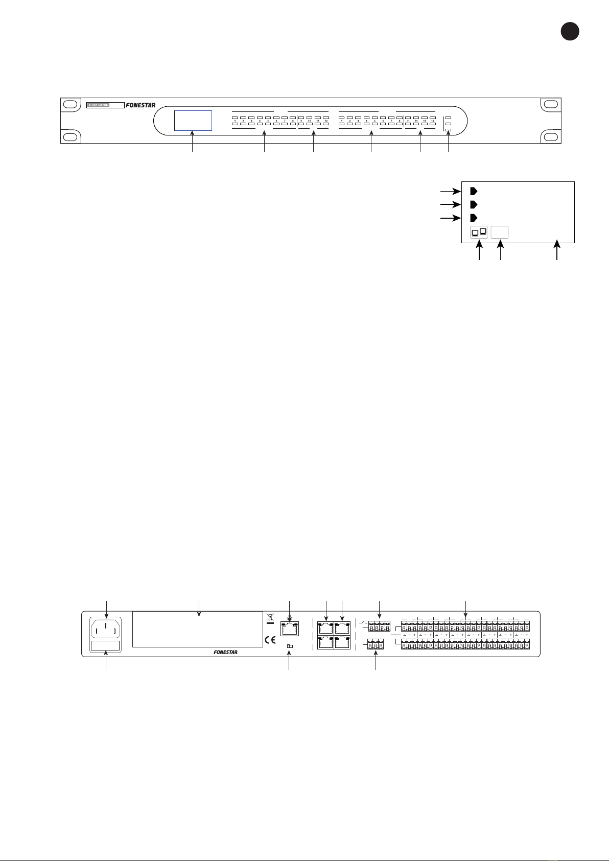
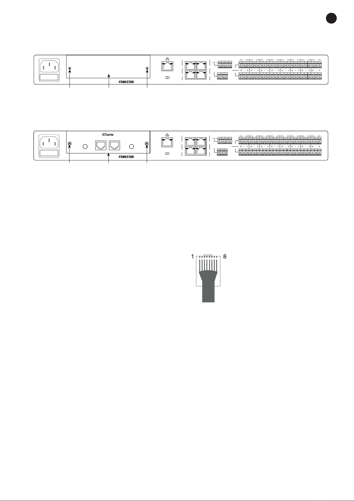
5.- RD 9/10 - 11/12: Ports corresponding to digital input and output channels, 9/10 and 11/12. Allow
the connection of the models MPX-400MIC, MPX-410ES, MPX-420V, MPX-430VS, MPX-460P and
MPX-440X for sending and receiving control signals and digital audio. RJ-45 connector.
NOTE: The models MPX-400MIC, MPX-410ES and MPX-430VS contain audio and therefore only one
device can be connected per RD port.
IMPORTANT : Do not connect an RD port to a router, the router may be damaged.
6.- RELAY: Contact closures that can be individually controlled via PC software. They can be used as
switches for other electrical devices. Euroblock terminals.
7.- INPUT/OUTPUT (1-8): Balanced analogue audio input/output euroblock terminals. Phantom 48 V
power available via PC software.
8.- FUSE: Protection fuse for the AC power circuit.
9.- LAN/RC-NET: Allows you to select the type of communication on the LAN (2) port between, TCP/IP in
LAN position or RS-485 in RC-NET position.
10.- RS-232: euroblock terminals for control via serial port.
OPTIONAL MODELS FOR MPX-4088 MATRIX
MPX-400MIC - Microphone for audio matrix
PUSH
8
1
5
7
6
2
3
4
9
ZONES
TALK
VOL./ALL ZONES
RD
BUSY
COM
CLIP
SIGNAL
ZONE SELECT/ PAGING MIC
MPX-400MIC
24 V DC 100 mA
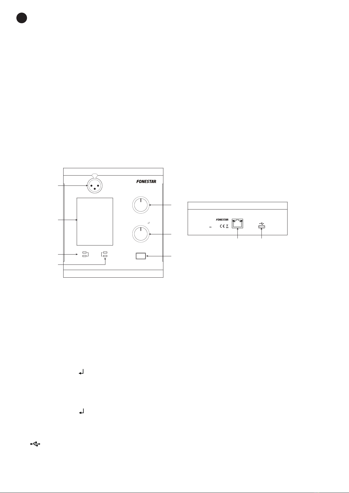
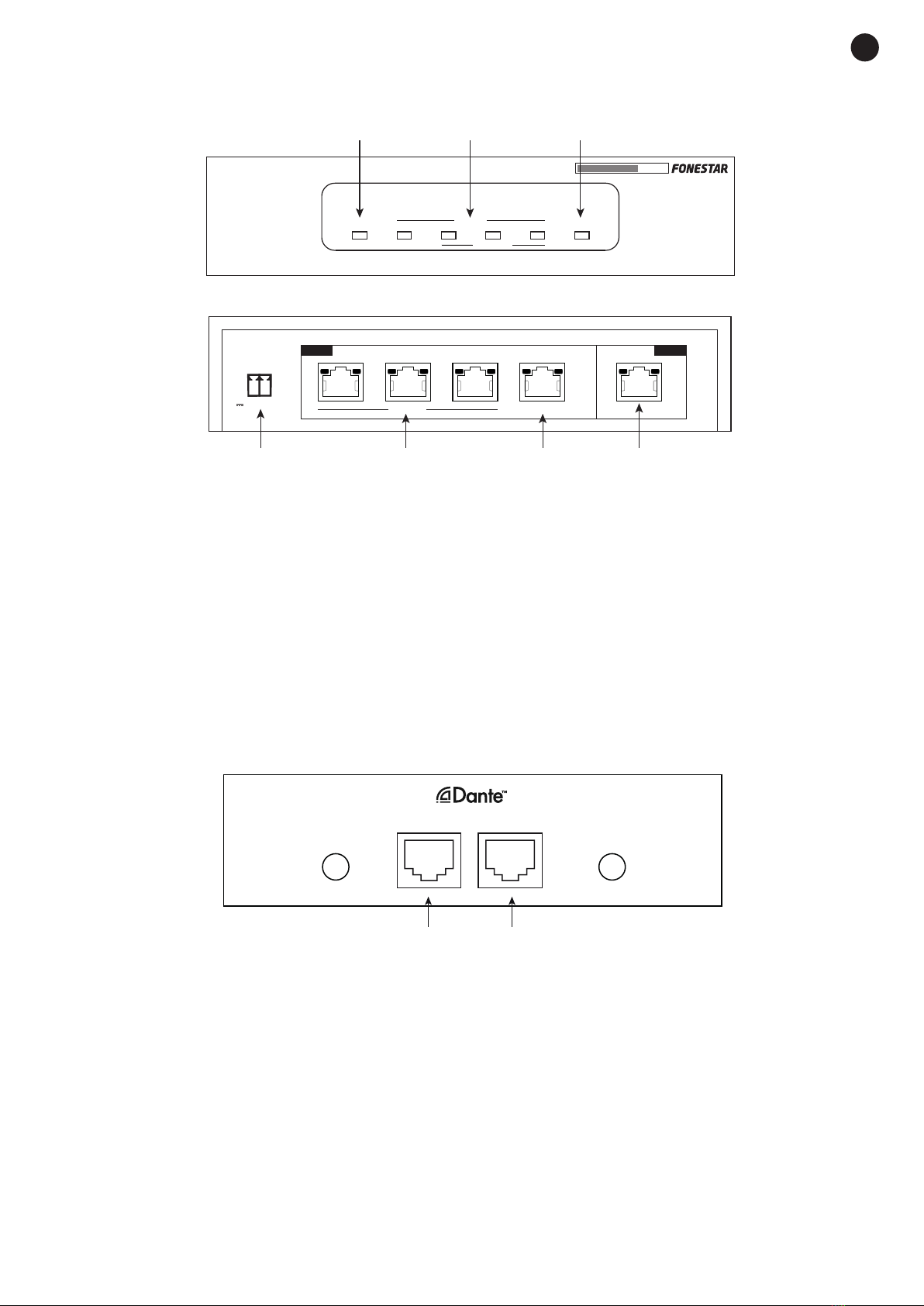
1.- XLR connector for electret condenser microphone.
2.- LCD information display, shows zones, volume, and ID number.
3.- Communication status LED indicator lights:
- COM: Correct communication between the MPX-4088 matrix and the MPX-400MIC microphone.
- BUSY: Communication problem between the MPX-4088 matrix and the MPX-400MIC microphone .
4.- LED signal indicator lights:
- SIGNAL: Indicates signal presence.
- CLIP - Indicates signal saturation.
5.- VOL/ALL ZONES: Microphone volume control for the selected zones. One press of the button selects
all zones. A long press of this button enters the edit mode of the MPX-400MIC.
6.- ZONE SELECT/ :Selects one or more zones by turning the knob left or right and pressing to select
them.
7.- TALK: When the button is pressed, the warning tone plays in the selected areas and the microphone
light ring lights up indicating that you can talk.
Note: To perform a factory reset, you must press and hold the buttons VOL/ALL ZONES and the
ZONE SELECT/ for more than 3 seconds.
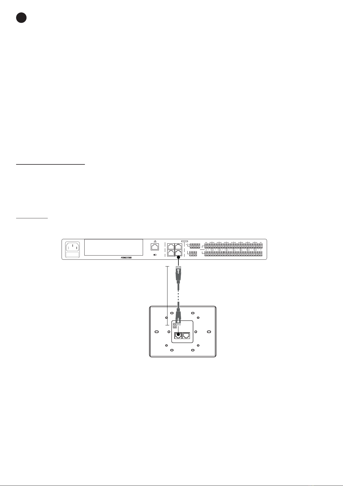
8.- RD: RD port for connection to MPX-4088 matrix on RD port 9/10 or 11/12 or AUDIO port of
MPX-440X. RJ-45 connector.
Note: The total cable distance must not exceed 150 meters for a Cat 5e STP cable.
9.- : Mini USB port for loading custom warning tones on MP3. To set a different warning tone, connect
the mini USB port to your PC, and replace it with the desired one. The maximum duration of the tones
is 4 seconds.

EN
- 5 -
Audio Input/Output Control
1 2 3
4 5 6
7 8 9
1.- A/B: Analogue line-level inputs assigned to channels 9 or 10 (A) and 11 or 12 (B) according to connection
to RD port 9/10 or 11/12 on the MPX-4088 audio array. 2 x RCA connectors.
2.- PHANTOM 48 V: Phantom power selector for XLR microphone input.
3.- INPUT: Signal indicators for channels A/MIC and B.
- SIGNAL: indicates signal presence on the corresponding channel.
- CLIP - Indicates signal saturation on the corresponding channel.
4.- MIC: XLR connector for microphone input, when the microphone is connected, the microphone signal
is mixed with the one on input channel A of the RCA connection.
5.- MIC LEVEL: Adjusts the volume level of the microphone.
6.- OUTPUT: Signal indicators for output channels 9/10 or 11/12 depending on connection on RD port
9/10 or 11/12 on the MPX-4088 audio matrix.
- SIGNAL: Indicates signal presence on the corresponding channel.
- CLIP - Indicates signal saturation on the corresponding channel.
7.- Euroblock connection terminals, corresponding to output channel 9 or 11.
8.- Euroblock connection terminals, corresponding to output channel 10 or 12.
9.- Rd port for connection to MPX-4088 matrix on RD port 9/10 or 11/12 or AUDIO port of MPX-440X port
extension . RJ-45 connector.
MPX-420V - Volume Control Knob
VOL./
1 2
3 4
1.- LCD DISPLAY: displays volume information in each zone and assigning inputs to zones.
2.- VOL./ :volume control and zone allocation.
3.- Rd port for connection to MPX-4088 matrix on RD port 9/10 or 11/12 ,CONTROL port of the port
extension MPX-440X or other remote controls MPX-420Vor MPX-460P RJ-45 connector.
4.- Rd LINK port for serial connection of the MPX-420V or MPX-460P remote controls .

EN
- 6 -
MPX-430VS - Volume Control Knob
VOL./
1 2
3 4 5
5.- LCD DISPLAY: displays volume information in each zone and assigning inputs to zones.
6.- VOL./ :volume control and zone allocation.
7.- Rd port for connection to MPX-4088 matrix on RD port 9/10 or 11/12 or AUDIO port of MPX-440X port
extension. RJ-45 connector.
8.- Euroblock connection terminals, corresponding to output channel 10 or 12.
9.- Euroblock connection terminals, corresponding to output channel 9 or 11.
MPX-460P - Touch-screen remote control
Input Output
Scene System
1 2
5
3 4 6 7
1.- INPUT: Access to input settings.
2.- OUTPUT: Access the output settings.
3.- SCENE: Access to programmed scenes.
4.- SYSTEM- Access to system settings.
5.- Power input 24 V DC, euroblock connector.
6.- Signal input to connect to the RD port of MPX-4088 matrix or CONTROL port of MPX-440X port
extension or to the LINK port of another MPX-460P or MPX-420V remote control, RJ45 connector.
7.- Link output for connecting more MPX-460P or MPX-420V remote controls, connector RJ45.

EN
- 7 -
MPX-440X - Matrix Port Extension
RD IN
RD IN 1 2 3 4 POWER
MPX-440XRD PORT EXPANSION
1
CONTROL AUDIO
234
24 V DC, 1 A
RD EXP
AUDIO CONTROL
RD EXP
4 5 6
1 2 3
7
1.- RD IN. LED indicator light for connection to MPX-4088 matrix.
2.- RD EXP: LED Indicator light for connection via RD EXP ports.
3.- POWER LED power indicator.
4.- Power supply 24 V DC, 1 A. Euroblock connector.
5.- RD EXP - CONTROL: Digital port for connection to MPX-420V or MPX-460P. RJ-45 connector.
6.- RD EXP - AUDIO: Digital port for connection to MPX-400MIC, MPX-410ES and MPX-430VS. RJ-45
connector.
7.- RD IN: Digital port for connection to MPX-4088 matrix on RD port 9/10 or 11/12. RJ-45 connector.
MPX-450D - DANTE Expansion Module
PRIMARY
ACT/LINK 1G 1GACT/LINK
SECONDARY
1 2
1.- PRIMARY: The primary port for connecting the MPX-4088 matrix to the router.
2.- SECONDARY: A secondary, or redundant, port for the optional connection of the MPX-4088 matrix to
the router that will be operational when the network connected to THE PRIMARY port fails.
Note: For Dante network configuration download the Dante Controller software from the following web
address: https://www.audinate.com/products/software/dante-controller
You can also download the instructions for configuring THE DANTE network from this web.

EN
- 8 -
INSTALLATION
MPX-410ES, MPX-420V y MPX-430VS
MPX-460P

EN
- 9 -
MPX-450D
- Remove the screws (1) and remove the protection plate (2) from THE DANTE expansion slot.
LAN RC-NET
~100-240 V AC,
50/60 Hz, 80 W
IN
RC-NET
LINK
9/10
INPUT
OUTPUT
RD
11/12
RS-232 G R T
1 2
RELAY 87654321
PRIMARY
ACT/LINK 1G 1GACT/LINK
SECONDARY
LAN RC-NET
~100-240 V AC,
50/60 Hz, 80 W
IN
RC-NET
LINK
9/10
INPUT
OUTPUT
RD
11/12
RS-232 G R T
1 2
RELAY 87654321
121
434
AUDIO MATRIX MPX-4088
- Then insert THE DANTE expansion module (3) into the expansion slot. Finally, secure the expansion
module with the screws (4).
LAN RC-NET
~100-240 V AC,
50/60 Hz, 80 W
IN
RC-NET
LINK
9/10
INPUT
OUTPUT
RD
11/12
RS-232 G R T
1 2
RELAY 87654321
PRIMARY
ACT/LINK 1G 1GACT/LINK
SECONDARY
LAN RC-NET
~100-240 V AC,
50/60 Hz, 80 W
IN
RC-NET
LINK
9/10
INPUT
OUTPUT
RD
11/12
RS-232 G R T
1 2
RELAY 87654321
121
434
AUDIO MATRIX MPX-4088
CONNECTION
STP CABLE FOR RD PORTS
The RD ports transmit and receive AES3 Plus control signals. The PIN-OUT for an RJ-45 connector and STP
cable is shown below.
1 Orange-White AES TX+
2 Orange AES TX-
3 Green-White AES RX+
4 Blue RS485 TX
5 Blue-White RS485 RX
6 Green AES RX-
7 Brown-White DC 24 V
8 Brown GND
CONNECTION OF BALANCED AUDIO INPUTS 1 TO 8 AND REMOTE ZONES
Connect the analogue audio sources/microphones to inputs 1 to 8 on the rear panel of the MPX-4088
matrix. The order in which the inputs are connected will allow them to be selected to each of the zones by
software or zone control knobs.
If the zones are equipped with the MPX-410ES remote audio input/output controller, it is possible to
connect the source directly to the microphone or line input, corresponding to lines 9/10 or 11/12 depending
on the RD port of the MPX-4088 matrix to which it is connected. Each matrix allows a maximum of two
MPX-410ES connected and operating simultaneously.
MICROPHONE CONNECTION WITH ZONE SELECTOR
Connect the MPX-400MIC zone selector microphone to the RD 9/10 or 11/12 inputs on the rear panel of
the MPX-4088 matrix using shielded Cat 5e cable with RJ-45 connector.
Note: It supports the connection of a maximum of two MPX-400MIC microphones per matrix, for
non-simultaneous use.

EN
- 10 -
CONNECTION OF ZONE OUTPUTS
- Each MPX-4088 matrix has 8 separate zones with balanced line-level output for connection of one power
stage or amplifier per zone.
- Connect the output of each zone to a line level input of the corresponding power amplifier or amplifier.
- Control the output volume with the PC software or from the controls on MPX-420V, MPX-430VS,
MPX-460P and then adjust the power amplifier or amplifier level to achieve a suitable volume on the zone
speakers.
Note: It is possible to extend the output zones to 12 with the connection of 2 audio input/output knobs
MPX-410ES or 2 zone control knobs with audio outputMPX-430VS .
CONNECTION OF ZONE CONTROLS
Each of the output zones can be controlled remotely using the MPX-420V, MPX-430VS or MPX-460P
controls. These controls allow you to select any of the selectable inputs 1 to 12 of the MPX-4088 matrix, as
well as to adjust the volume for each remote zone.
The MPX-430VS has two audio outputs corresponding to channels 9/10 or 11/12 depending on the RD port
of the MPX-4088 to which it is connected.
MPX-420V/MPX-430VS
Connect the MPX-420V or MPX-430VS with Cat 5e cable or higher, RJ-45 connector to RD 9/10 or 11/12
ports on the matrix.
Note: You can connect up to 8 MPX-420V controllers maximum in series, for a maximum distance of 150
meters with shielded network cable Cat 5e or higher or 5 MPX-420V and 5 MPX-460P maximum in series,
for a maximum distance of 100 m with Cat 5e or higher shielded network cable.
MPX-460P
OPTION 1: Direct connection of 1 MPX-460P for a total distance of 100 m. FTP Cat 5e cable.
LAN RC-NET
~100-240 V AC,
50/60 Hz, 80 W
IN
RC-NET
LINK
9/10
11/12
INPUT
OUTPUT
RD
RS-232 G R T
1 2
RELAY 87654321
AUDIO MATRIX MPX-4088
INPUT
100 m max.
~100-240 V AC,
50/60 Hz, 80 W
SINGLE
INPUT LINK
100 m max.
INPUT LINK INPUT
...
...
...
8 max.
+
AUDIO MATRIX MPX-4088
INPUT INPUTLINK
100 m max.
INPUT LINK INPUT
... ...
5 x MPX-460P max.
5 x MPX-420V max.
+
LAN RC-NET
~100-240 V AC,
50/60 Hz, 80 W
IN
RC-NET
LINK
9/10
11/12
INPUT
OUTPUT
RD
RS-232 G R T
1 2
RELAY 87654321
IN
OUT
LINK
MPX-420V
IN
OUT
MPX-420V
AUDIO MATRIX MPX-4088
SERIES
MIXED
RD
RD
RD
24 V CC, 300 mA 24 V CC, 300 mA

EN
- 11 -
OPTION 2: Up to 8 MPX-460P serial connection
for a total distance of Cat FTP cable. 5e less than 100 m.
Note: 24 V DC, 300 mA power adapter required.
LAN RC-NET
~100-240 V AC,
50/60 Hz, 80 W
IN
RC-NET
LINK
9/10
11/12
INPUT
OUTPUT
RD
RS-232 G R T
1 2
RELAY 87654321
AUDIO MATRIX MPX-4088
INPUT
100 m max.
~100-240 V AC,
50/60 Hz, 80 W
SINGLE
INPUT LINK
100 m max.
INPUT LINK INPUT
...
...
...
8 max.
+
AUDIO MATRIX MPX-4088
INPUT INPUTLINK
100 m max.
INPUT LINK INPUT
... ...
5 x MPX-460P max.
5 x MPX-420V max.
+
LAN RC-NET
~100-240 V AC,
50/60 Hz, 80 W
IN
RC-NET
LINK
9/10
11/12
INPUT
OUTPUT
RD
RS-232 G R T
1 2
RELAY 87654321
IN
OUT
LINK
MPX-420V
IN
OUT
MPX-420V
AUDIO MATRIX MPX-4088
SERIES
MIXED
RD
RD
RD
24 V DC, 300 mA 24 V DC, 300 mA
OPTION 3: Serial connection of MPX-460P (up to 5 maximum) along with MPX-420V controls (up to 5 maximum)
for a total distance of FTP Cat cable. 5e less than 100 m.
Note: 24 V DC, 300 mA power adapter required for each MPX-460P.
LAN RC-NET
~100-240 V AC,
50/60 Hz, 80 W
IN
RC-NET
LINK
9/10
11/12
INPUT
OUTPUT
RD
RS-232 G R T
1 2
RELAY 87654321
AUDIO MATRIX MPX-4088
INPUT
100 m max.
~100-240 V AC,
50/60 Hz, 80 W
SINGLE
INPUT LINK
100 m max.
INPUT LINK INPUT
...
...
...
8 max.
+
AUDIO MATRIX MPX-4088
INPUT INPUTLINK
100 m max.
INPUT LINK INPUT
... ...
5 x MPX-460P max.
5 x MPX-420V max.
+
LAN RC-NET
~100-240 V AC,
50/60 Hz, 80 W
IN
RC-NET
LINK
9/10
11/12
INPUT
OUTPUT
RD
RS-232 G R T
1 2
RELAY 87654321
IN
OUT
LINK
MPX-420V
IN
OUT
MPX-420V
AUDIO MATRIX MPX-4088
SERIES
MIXED
RD
RD
RD
24 V DC, 300 mA 24 V DC, 300 mA
CONNECTION OF THE MPX-440X RD PORT EXTENSION
1.- Connect the RD IN port of the mod. MPX-440X to RD ports 9/10 or 11/12 on the matrix
2.- Switch on the mod. MPX-420V, MPX-460P to RD ports EXP CONTROL
3.- Switch on the mod(s). MPX-400MIC, MPX-410ES , OR MPX-430VS TO RD EXP AUDIO PORT.
IMPORTANT :
- Use data cable Cat5e or higher.
- The total cable distance must not exceed 150 meters for a STP Cat 5e cable.
RD EXP RD IN
AUDIO
CONTROL
MPX-4088
MPX-400MIC,
MPX-410ES or
MPX-430VS
MPX-420V or
MPX-460P

EN
- 12 -
START-UP
- Make the connections with the amplifier and all the components of the audio system switched off and
disconnected from the power supply. Always start with the volume controls at minimum. Slowly move
the controls.
- Firstly, connect the audio sources to the inputs. Poor connections can cause noise and interference.
Use suitable and not excessively long cables for connections: Shielded cables, preferably low capacity.
- Connect the, MPX-420V MPX-430VS or MPX-460P remote control knobs to the desired zones and
connect the MPX-400MIC zone selector microphone, MPX-410ES remote audio input/output remote
control, or MPX-440X extension to the RD ports of the matrix using Cat 5e cable or higher.
- Connect a power amplifier or amplifier to the OUTPUT output of each zone to be used. You can use 100
V or 4-8 Ω low impedance line amplifiers depending on the type of speakers you are connecting.
- Once the connections are made according to your needs, connect the system to the mains and turn it
on. After use, do not forget to switch it off and disconnect it from the mains.
Connecting Device
With the MPX-4088 matrix , you can configure a system from 12 zones (1 matrix) to 192 zones (16 matrixes).
By installing DANTE MPX-450D modules in the matrixes we will be able to use more than 1 matrix, expanding
the inputs and outputs, and creating a system compatible with other DANTETM systems.
The configuration and assignment of inputs and outputs and volume control can be performed from the
various MPX-420V, MPX-430VS or MPX-460P controls.
Each matrix has:
- 8 analogue audio inputs
- 8 analogue audio outputs (output zones)
- 2 RD ports with 4 input and output channels. On each port you can connect:
- 1 audio device: MPX-400MIC, MPX-410ES or MPX-430V.
- Up to 8 MPX-420V (Cat. 5e or greater total length 150 m maximum).
- Up to 8 MPX-460P (Cat. 5e or greater total length 100 m maximum).
- Up to 5 MPX-420V and 5 MPX-460P (Cat. 5e or greater total length 100 m maximum).
- 1 MPX-440X Port Expansion (STP Cat. 5e cable 150 m maximum length).
The following are some examples of equipment connections:
CONFIGURATION 1
Example with an MPX-4088 matrix.
~100-240 V AC,
50/60 Hz, 80 W
LAN RC-NET
RC-NET
IN
LINK
RD
9/10
11/12
RELAY
RS-232
1 2
GRT OUTPUT
INPUT
8 7 6 5 4 3 2 1
ETHERNET SWITCH
MPX-4088
AUDIO MATRIX MPX-4088
AMPLIFIER
ZONE 1
MPX-420V or
MPX-460P
MPX-420V or
MPX-460P
MPX-420V or
MPX-460P
MPX-400MIC,
MPX-410ES or
MPX-430VS
MP3 PLAYER

EN
- 13 -
CONFIGURATION 2
Example with an MPX-4088 matrix and a MPX-440X port extension.
~100-240 V AC,
50/60 Hz, 80 W
LAN RC-NET
RC-NET
IN
LINK
RD
9/10
11/12
RELAY
RS-232
1 2
GRT OUTPUT
INPUT
8 7 6 5 4 3 2 1
ETHERNET SWITCH
MPX-4088
MPX-440X
AUDIO MATRIX MPX-4088
AMPLIFIER
MPX-400MIC, MPX-410ES
or MPX-430VS
MPX-420V or
MPX-460P
MPX-420V or
MPX-460P
MPX-420V or
MPX-460P
MPX-420V or
MPX-460P
MPX-420V or
MPX-460P
MPX-420V or
MPX-460P
MPX-420V or
MPX-460P
MPX-420V or
MPX-460P
MPX-400MIC,
MPX-410ES or
MPX-430VS
MP3 PLAYER
ZONE 1
MPX-420V or
MPX-460P
CONFIGURATION 3
Example with 2 MPX-4088 matrix connected by DANTE MPX-450D expansion modules and a RD
MPX-440X port extension .
AUDIO MATRIX MPX-4088
~100-240 V AC,
50/60 Hz, 80 W
LAN RC-NET
RC-NET
IN
LINK
RD
9/10
11/12
RELAY
RS-232
1 2
GRT OUTPUT
INPUT
8 7 6 5 4 3 2 1
~100-240 V AC,
50/60 Hz, 80 W
LAN RC-NET
RC-NET
IN
LINK
RD
9/10
11/12
RELAY
RS-232
1 2
GRT OUTPUT
INPUT
8 7 6 5 4 3 2 1
ROUTER
MPX-4088
MPX-450D
MPX-4088
MPX-450D
MPX-440X
PRIMARY
ACT/LINK 1G 1GACT/LINK
SECONDARY
PRIMARY
ACT/LINK 1G 1GACT/LINK
SECONDARY
AMPLIFIER
ZONE 1
MPX-400MIC,
MPX-410ES or
MPX-430VS
MPX-400MIC,
MPX-410ES or
MPX-430VS
MPX-400MIC,
MPX-410ES or
MPX-430VS
DVD PLAYER
AMPLIFIER
MPX-420V or
MPX-460P
MPX-420V or
MPX-460P
MPX-420V or
MPX-460P
MPX-420V or
MPX-460P
MPX-420V or
MPX-460P
MPX-420V or
MPX-460P
MPX-420V or
MPX-460P
MPX-420V or
MPX-460P
MPX-420V or
MPX-460P
MPX-420V or
MPX-460P
MPX-420V or
MPX-460P
MPX-420V or
MPX-460P
MP3 PLAYER
ZONE 13

EN
- 14 -
FIRMWARE UPGRADE
To update the MPX-4088, MPX-400MIC, MPX-410ES, MPX-420V, MPX-430VS firmware, MPX-460P and
MPX-440X, the Firmware Update Tool must be downloaded. Go to:
www.fonestar.com/MPX-4088 and go to the Software section to download the Firmware Update Tool.
Connect your PC to the same network as the MPX-4088 matrix, run the Firmware Update Tool, and perform
the following steps:
1.- Press the SETUP button and select the IP of the device to update.
2.- Then press the CONNECT button. If the connection is successful, the connection indicator turns green
and all devices connected to the matrix are displayed.
3.- Select the device you want to update, click Firmware Update, and then click Update Firmware to
proceed with the update.
4.- Wait for the update to complete and the computer to restart.

EN
- 15 -
CONFIGURING NETWORK PARAMETERS
It is possible to manually configure the network parameters of the MPX-4088 matrix by going to
www.fonestar.com/MPX-4088 section Software to download the LAN Module Config Tool.
Connect your PC to the MPX-4088 matrix, run the Network Configuration Tool, and perform the following
steps:
1.- Press the SETUP button, select the IP of the device to be configured, and press the Config button.
2.- In the next window, enter the setup ID and password. The default ID is: Admin, the password is: system.
3.- To configure the desired network parameters, scroll through the available sections in the sidebar and
set the parameters to the desired values.

EN
- 16 -
GENERAL RECOMMENDATIONS
MPX-4088 NETWORK CONNECTION
1.- For Star Network Mode matrix connection, place the selector LAN/RC-Net in the LAN position on all
matrixes in the installation.
2.- For Daisy chain network mode connection, this selector must be in the LAN position on the first matrix
and in the RC-Net position on the other cascaded matrixes.
3.- It is recommended that you connect the MPX-4088 matrix and PC to the same network using a router.
It is recommended not to connect the MPX-4088 directly to the PC, or through a switch, to avoid
problems with the network addresses between the two devices. Before running the MPX-4088 software,
ensure that the PC network adapter is configured to obtain an IP automatically (DHCP active) and that
it does not have a fixed IP assigned.

EN
- 17 -
If you do not have a router, you must manually set the network addresses of the PC and the MPX-4088
matrix.
To change the network configuration of the matrix, you must do so through the configuration software
“MPX-4088_LAN_module_Config_tool_V0.7”, available at: www.fonestar.com/MPX-4088 on THE
SOFTWARE tab.
4.- If your PC has different network adapters (cable, WiFi, etc.) it is not recommended to use them at the
same time. For example: If the connection to the MPX-4088 is made through a wired connection, it is
not recommended to connect to a Wi-Fi network at the same time. Disable network adapters that are
not using the MPX-4088 matrix.
Make sure that your PC has only one active network connection, otherwise you will receive a “Detected
multiple network cards or invalid” error message when trying to connect to the MPX-4088 matrix, telling
you that the connection was not possible.
After disabling the network adapters, it is recommended that you restart your PC.
5.- If the software suddenly loses the connection during setup, it may be due to the following reasons:
a.- The MPX-4088 matrix has been disconnected from the network. Check the status of the Ethernet
cable.
b.- The PC has been disconnected from the network. Check the status of the Ethernet cable.
c.-
A new device has been connected to the network using the same IP address as the PC or
MPX-4088 matrix. Check the IP address of the various devices connected to the network.
d.- Another PC or device on the network is attempting to connect to the MPX-4088 matrix. Check the
computers on your network so that only one computer is connected to the MPX-4088 matrix at a
time.
6.- If you try to access the MPX-4088 matrix control software, you receive a “Recall Current Scene Failure”
error message. Access the matrix network module configuration via the “MPX-4088_LAN_module_
Config_tool_V0.7” utility and verify that the configuration of the various network module parameters
matches the following:

EN
- 18 -

EN
- 19 -
CONNECTING AND CONFIGURING MPX-450D (DANTE NETWORK)
After installing the MPX-450D expansion module on the rear panel of each MPX-4088 matrix in our
installation, we must download the Audinate control software from:
https://www.audinate.com/products/software/dante-controller.
Next, we must redirect the outputs (output 1 to output 8) of the first MPX-450D module to the inputs (input
1 to input 8) of the second and so on (2 to 3, 3 to 4, etc.). Finally, we must redirect the outputs (output 1 to
output 8) of the last MPX-450D module to the inputs of the first module (input 1 to input 8).
Example:

EN
- 20 -
Next, in the matrix program itself, we must redirect the NET inputs and outputs of all MPX-4088 matrixes in
the installation, making a diagonal between the NET inputs and outputs, as follows:
When we want to share an analogue input of an matrix on the NET channels (to be visible and selectable as
an audio source by the other matrixes in the installation), we must select the analogue input we want (IN01
to IN12), mark it on the channel (NET01 to NET 08) that we want and unmark it from the diagonal NET, as
follows:
In this image, analogue input channels 1, 2 and 3 have been assigned to analogue outputs 1, 2 and 3 of the
matrix and input channels 1, 2 and 3 have been sent to NET channels 1, 2 and 3.
If we want to extract that audio from the NET channels to another matrix in our network, we will simply need
to select the desired NET channel and mark it on the corresponding analogue output.
In this case, the NET 1 channel will output through the analogue output 1 of the matrix.
Other manuals for MPX-4088
1
Table of contents
Languages:
Other FONESTAR Stereo System manuals