Fonrich FR-DCBS-AFS8B User manual

User Manual
Version 1.0
Arc Fault Protection Box FR-DCBS-AFS8B
Scan code to learn more
Fonrich (Shanghai) New Energy Technology Co., Ltd.
Add: 1st Floor, Building 5, No.999 Jiangyue Road, Minhang District,Shanghai
Web: www.fonrich.com
Tel:+86 21 61679671
Email: [email protected]

1
Table of Contents
Table of Contents........................................................................................................................1
Preface........................................................................................................................................ 3
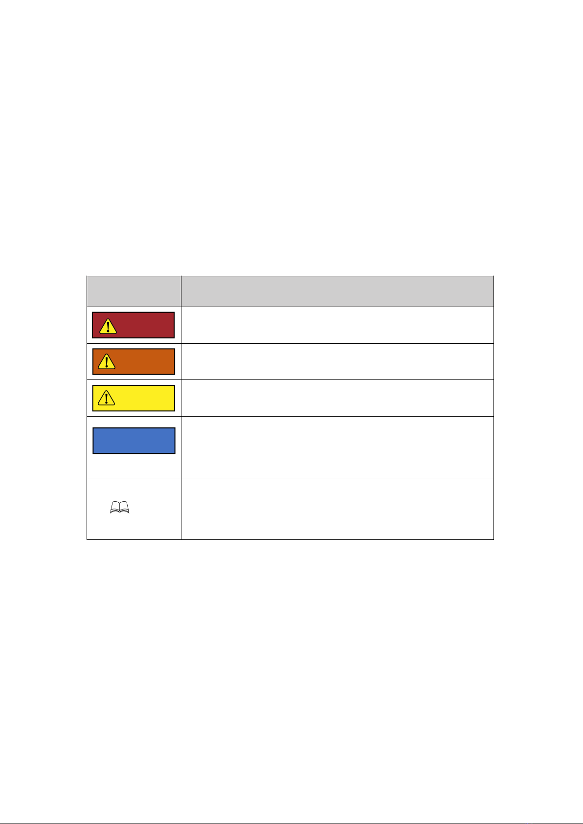
1 Safety Precautions....................................................................................................................4
2 Product Overview.................................................................................................................... 6
2.1 Description........................................................................................................................6
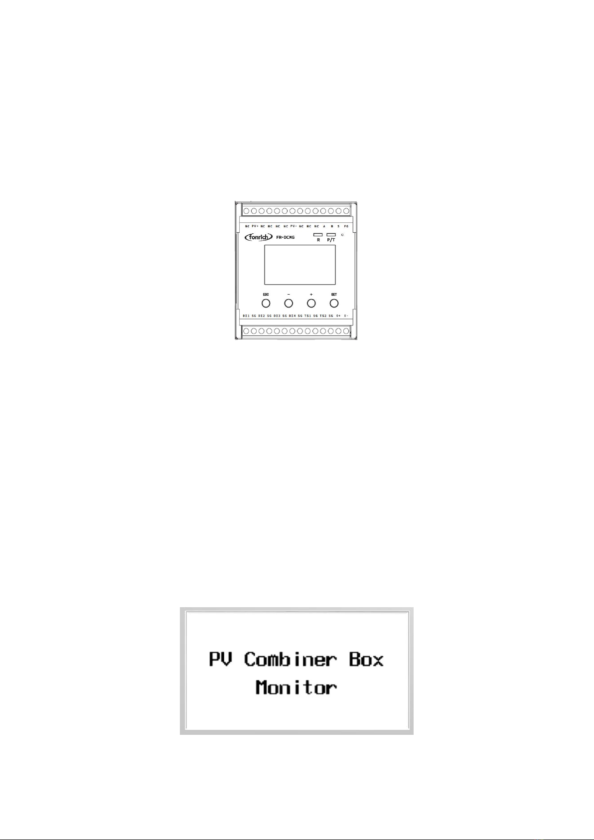
2.2 Appearance....................................................................................................................... 7
2.3 Principles of Design..........................................................................................................7
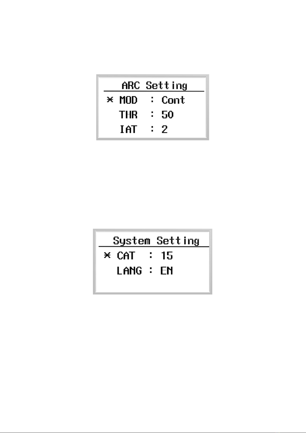
2.4 Arc alarm strategy.............................................................................................................8
2.4.1 Arc mode....................................................................................................................8
2.4.2 Arc alarm strategy......................................................................................................8
3 Installation............................................................................................................................... 9
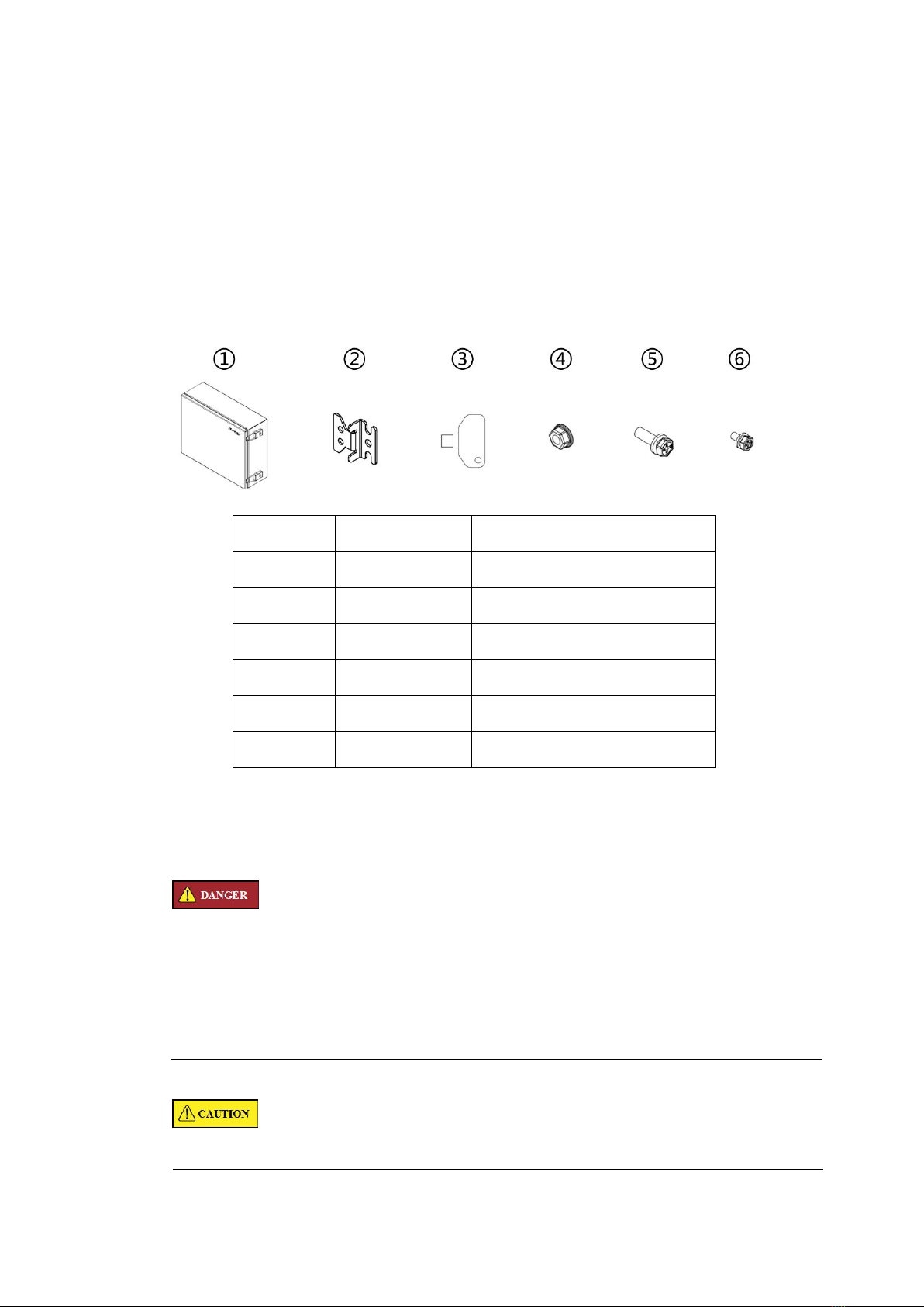
3.1 Scope of Delivery............................................................................................................. 9
3.2 Requirements for Installation............................................................................................9
3.3 Procedure........................................................................................................................ 10
4 Electrical Connection.............................................................................................................11
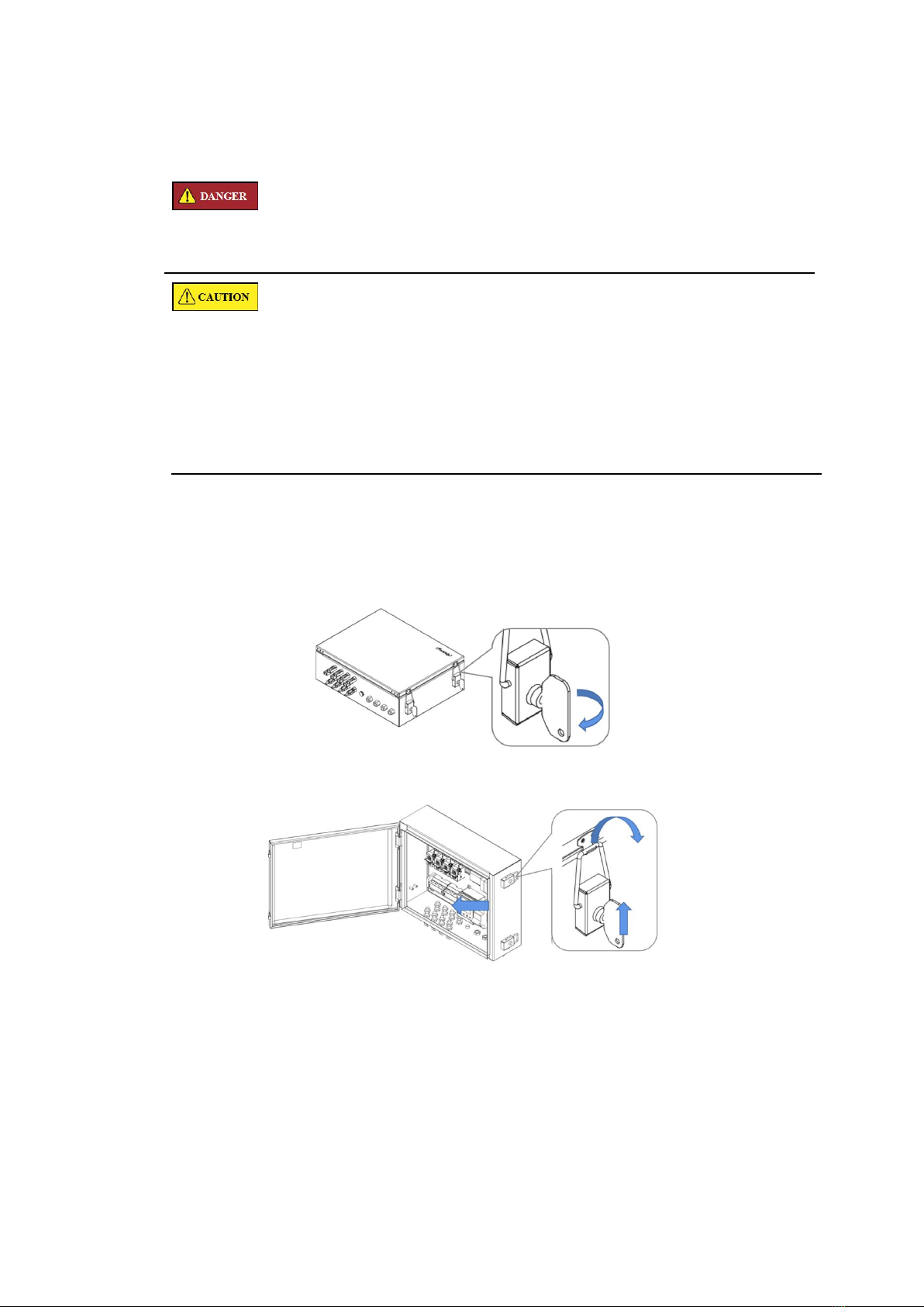
4.1 Opening the product....................................................................................................... 11
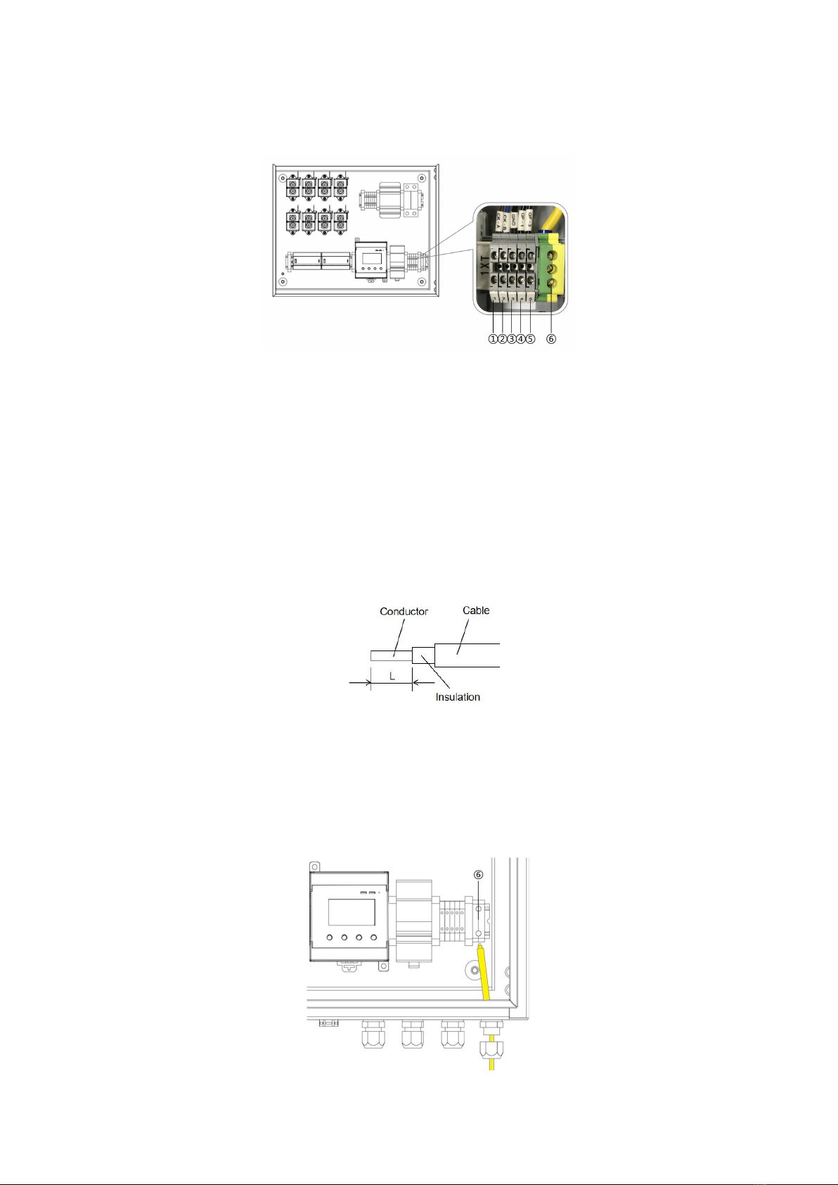
4.2 Overview of the Connection Area.................................................................................. 12
4.3 PE cable connection........................................................................................................12
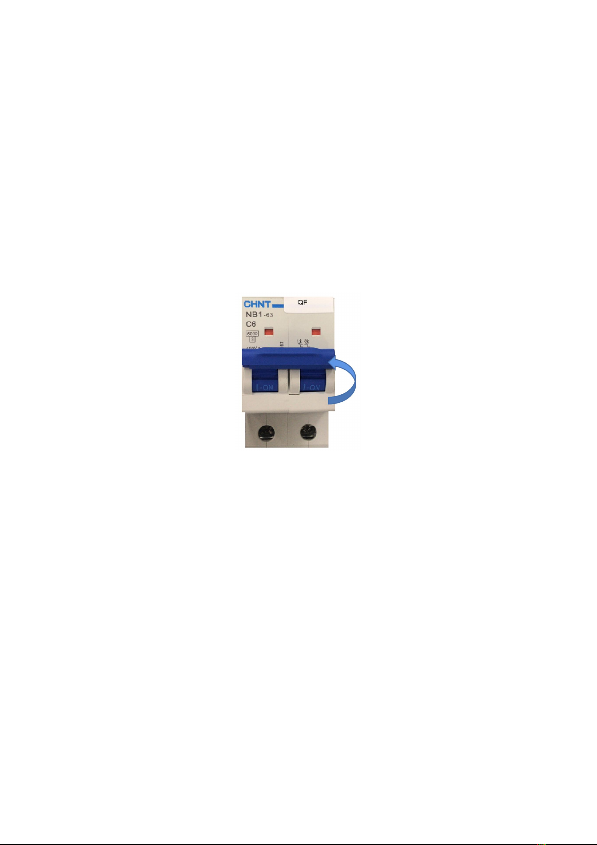
4.4 AC power cable connection............................................................................................13
4.5 RS485 cables connection................................................................................................13
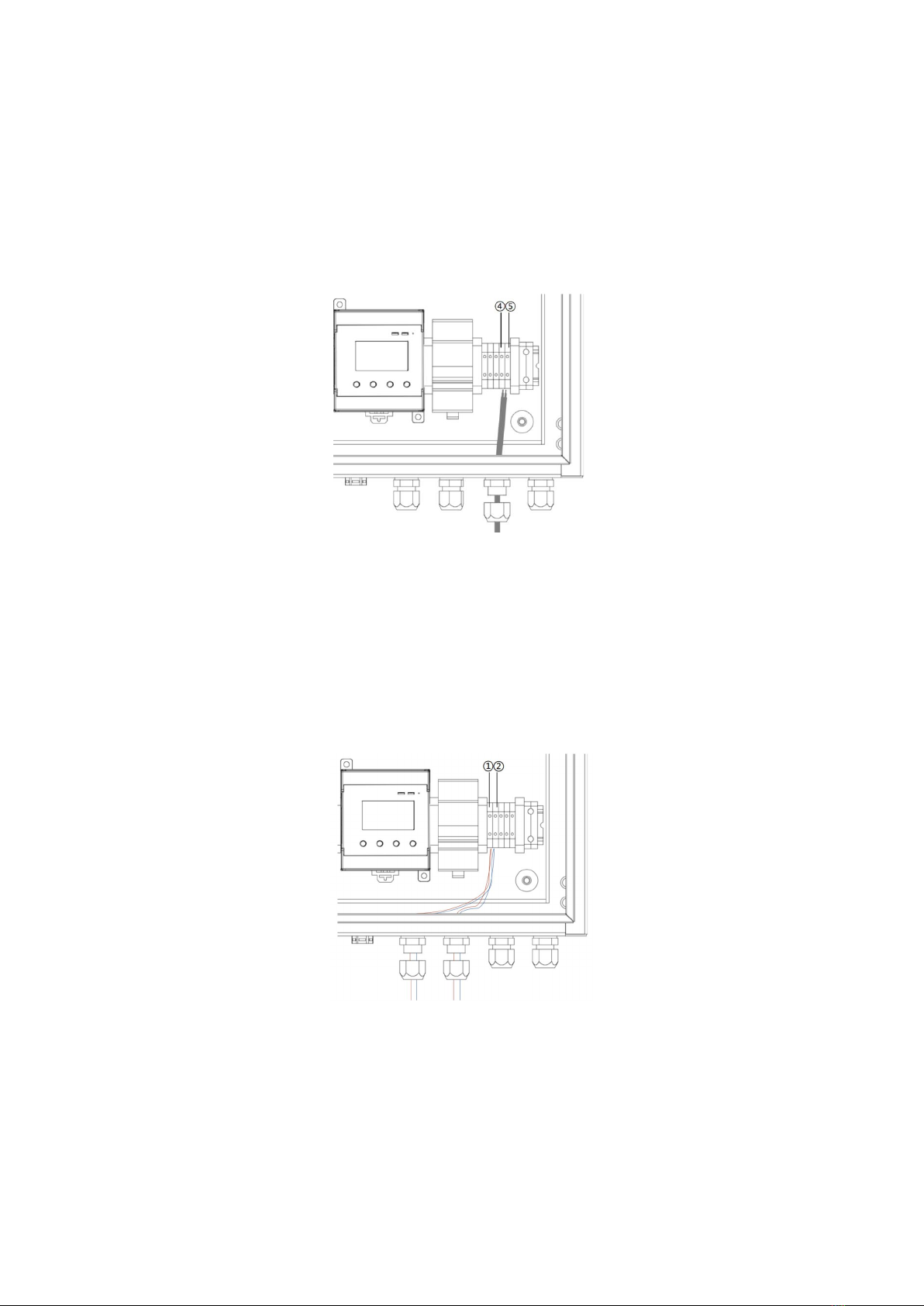
4.6 PV String Cables Connection......................................................................................... 13
5 Operation............................................................................................................................... 15
5.1 Checking before Operation.............................................................................................15
5.2 Operation........................................................................................................................ 15
6 Setting.................................................................................................................................... 16
6.1 Host Module................................................................................................................... 16
6.2 Power On Interface......................................................................................................... 16
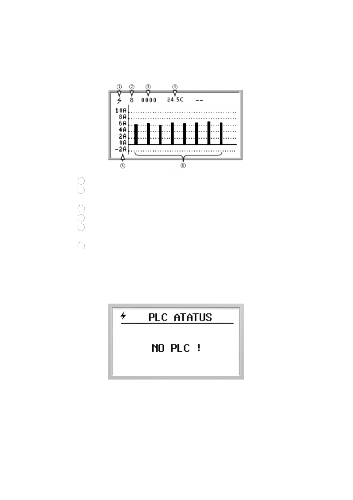
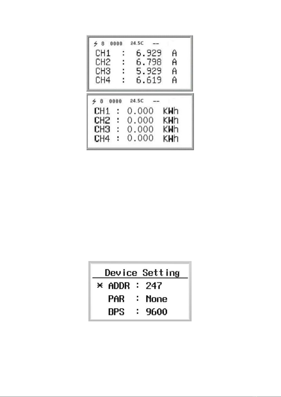
6.3 Current Interface.............................................................................................................17
6.4 Current and Power Generation Data Interface................................................................17
6.5 Setting Interface..............................................................................................................18

Fonrich New Energy Technology Co., Ltd.
2
6.3.1 Device Setting Interface.......................................................................................... 18
6.3.2 Arc Setting Interface................................................................................................19
6.3.3 System Setting Interface.......................................................................................... 19
6.6 Current Calibration Setting Interface..............................................................................19
6.7 SHTPA Interface............................................................................................................ 20
6.8 CBM Information Interface............................................................................................ 20
6.8 Arc Fault Alarm Interface...............................................................................................21
6.9 Alarm Clearing Interface................................................................................................ 21
7 MODBUS Protocol Definition.............................................................................................. 22
7.1 Communication Format Configuration...........................................................................22
7.2 Function Code Description............................................................................................. 22
7.3 Register Description....................................................................................................... 23
7.3.1 Register Description In Bit Units (function code 02)..............................................23
7.3.2 Register Description In Word Unit (function code 03 04 06)................................. 24
8 Appendix................................................................................................................................29
8.1 Revision Log...................................................................................................................29
8.2 Contact Us...................................................................................................................... 29

3
CAUTION
Preface
Instruction
This user manual describes introduction, installation, electrical connection and
operation in detail for FR-DCBS-AFS8B users. Before installing and operating of the
equipment, you should read and understand all the instructions and be familiar with
the relevant safety in relevant paragraphs.
Target Group
This user manual is intended for operators and end users.
Signs
The following signs may appear in this article, and their meanings are as follows.
Signs
Instructions
Indicates a hazardous situation which,if not avoided, will result
in death or serious injury.
Indicates a hazardous situation which,if not avoided, could
result in death or serious injury.
Indicates a hazardous situation which,if not avoided, could
result in minor or moderate injury.
Indicates a situation which,if not avoided, can result in property
damage.
It is not safety warning information, and does not involve
personal, equipment and environmental damage.
Note
Protrudes important or critical information, best practices, tips,
etc.
It is not safety warning information, and does not involve
personal, equipment and environmental damage.
WARNING
DANGER
NOTICE

4
1 Safety Precautions
To prevent personal injury and property damage, read this section carefully and
observe all safety information at all times.
Requirements of operators
Operators must have the following skills:
Knowledge of how an arc fault production box works and is operated.
Training in how to deal with the dangers and risks associated with installing,
using electrical devices and installations.
Knowledge of and compliance with this document and all safety information.
Installation
Disconnect the product form voltage sources and make sure it cannot be
reconnected before working on the device.
Please do not touch the other parts inside in addition to the terminals during the
installation process.
Please read this user manual carefully before installation. If the equipment is
damaged resulting from violation of the regulations specified in this document,
our company has the right not to guarantee the quality.
The distance between FR-DCBS-AFS8B and the object should meet the
conditions.
Electrical connection
Before electrical connection, please make sure that FR-DCBS-AFS8B is not
damaged and in a safe state, otherwise it may cause electric shock or fire.
Touch the cables of the PV array on the insulation only.
All electrical connections must meet the electrical standards of the country or
region where they are located.
Please use the indicated electric wire and electric cable. Using electric wire and
electric cable with no sufficient capacity or with no correct connection method
will lead to machine breakdown, machine fire or electric shock.

5
Operation
FR-DCBS-AFS8B has high voltage during operation, which may cause electric
shock or death in severe cases. Please operate strictly in accordance with the
safety precautions listed in this manual and other related documents.

6
2 Product Overview
2.1 Description
FR-DCBS-AFS8B Arc Fault Protection Box is a solar AFCI (Arc Fault Circuit
Interrupter), which is mainly used in middle sizes of distributed PV system, such as
20-200KW rooftop solar system.
Functions
Its main function is to detect the arc fault of the PV
strings and disconnect the string cables when arc fault
occurs. If the arc fault is detected, it will issue an alarm
signal by local LCD and RS485. At the same time, the DC
relays will be driven to break off the DC circuit, which can
effectively prevent fire hazard. In addition, it has the
function of real-time monitoring the current of each PV
string and communicating with the host PC by RS485 to
realize remote monitoring.
Features
8 PV strings each box supports, be parallel running to support larger system
Fonrich IP technology to self-adapt with different inverters
UL 1699B 2018 conformity
The protection arc sensitivity is adjustable
Arc fault detecting of each PV string
Remote monitoring with Modbus RS485
Application
FR-DCBS-AFS8B is mainly used in middle sizes of distributed PV system, such
as 20-200KW rooftop solar system. The system consists of PV strings, arc fault
protection box, inverter and grid, as shown in the figure below.

7
2.2 Appearance
Dimensions(mm)
Ports
2.3 Principles of Design
Schematic Diagram
If the arc fault is detected, AFS8B will issue an alarm signal by the LCD and
RS485. At the same time, the DC relay will be driven to break off the DC circuit. So
that the DC circuit is in the state of no current.
After 3 minutes, the DC relay will be driven to turn on the DC circuit and then
the entire circuit resumes normal operation.
However, when the arc alarm times is up to 5, AFS8B must be restarted manually.

8
2.4 Arc alarm strategy
2.4.1 Arc mode
We divide the arcs into Instantaneous Arc and Continuous Arc.
Instantaneous Arc
The arc duration does not exceed the Instantaneous Arc Time (IAT), and there is
no arc occurring again within the Continuous Arc Time (CAT).
Continuous Arc
The arc duration exceeds the IAT, or the arc duration does not exceed the IAT,
but the arc occurs again within the CAT.
2.4.2 Arc alarm strategy
1. Instantaneous arc alarm mode
If the arc intensity of any channel exceeds the channel alarm threshold, an arc
alarm will be generated.
2. Continuous arc alarm mode
The product does not alarm when instantaneous arc is detected, but only when
continuous arc is detected.

9
3 Installation
3.1 Scope of Delivery
Check the scope of delivery for completeness and any externally visible damage
before installation. Contact your distributor if the scope of delivery is incomplete or
damaged.
Product and accessories
3.2 Requirements for Installation
Do not install the product in areas containing highly flammable material or
grass.
Do not install the product in potentially explosive atmospheres.
Disconnect the product from voltage sources and make sure it cannot be
reconnected before working on the device.
Do not install the product in the area where can be touched unintentionally.
Position
Quantity
Designation
①
1
Arc Fault Protection Box
②
4
Fixture
③
2
Lock Key
④
4
Hex Nut M8
⑤
4
Bolt M8×25, Hex head
⑥
8
Bolt M6×12, Hex head

10
Take wall-mounted installation as an example to introduce:
A solid support surface must be available.
The ambient temperature range is -30℃ ~ +60℃.
The protection level of FR-DCBS-AFS8B is IP65, and it can be used in both
indoor and outdoor environments.
Recommended installation clearances
If you maintain the recommended clearances,adequate heat dissipation will be
ensured. Thus,you will prevent power reduction due to excessive temperature.
Maintain the recommended clearances to walls as well as to other products or
objects.
(Dimensions in mm)
3.3 Procedure
1) Place the four fixtures under the four corners of the product bottom, screw the
four fixtures to the product using the Bolt M6×12.
2) Place the product vertically on the wall and use the screws to attach the four
fixtures of the product to the wall.

11
4 Electrical Connection
Before electrical connection, please make sure that FR-DCBS-AFS8B is not
damaged and in a safe state, otherwise it may cause electric shock or fire.
Touch the cables of the PV array on the insulation only.
All electrical connections must meet the electrical standards of the country or
region where they are located.
Please use the indicated electric wire and electric cable. Using electric wire and
electric cable with no sufficient capacity or with no correct connection method
will lead to machine breakdown, machine fire or electric shock.
4.1 Opening the product
1) Use the key to open the lock
2) Pull the buckle up, and pull the hook down, then open the lid.

12
4.2 Overview of the Connection Area
①②: RS485 Terminals.
③: GND Terminal of RS485 shielded wire.(RS485 shielded wire only needs to
be grounded at a single point, you can choose one device to connect to the
GND terminal or ground outside the device, and the GND terminal is not
used.)
④⑤: AC Power Terminals.
⑥: PE Terminal.
4.3 PE cable connection
1) Strip the insulation of the PE cable.
L is the reference value of the exposed length of the conductor of the PE cable.
The length of L is recommended to be 9-11mm.
2) Open the PE waterproof terminal and pass the PE cable through the PE
waterproof terminal.
3) Connect the PE cable to the PE terminal ⑥, and then tighten the PE terminal
⑥with a flat-blade screwdriver.

13
4.4 AC power cable connection
1) Strip the insulation of the AC power cable.
2) Open the AC power waterproof terminal and pass the AC power cable through
the AC power waterproof terminal.
3) Connect the AC power cable to the AC power terminals④⑤, and then tighten
the AC power terminals④⑤ with a flat-blade screwdriver.
4.5 RS485 cables connection
1) Strip the insulation of the RS485 cables.
2) Open the RS485 waterproof terminal and pass the RS485 cables through the
AC power waterproof terminal.
3) Connect the RS485 cables to the RS485 terminals①②, and then tighten the
AC power terminals①② with a flat-blade screwdriver.(Note:A and B cannot
be reversed)
4.6 PV String Cables Connection
1) Connect the PV+ of the PV string to the Input+ of AFS8B in turn.
2) Connect the Output+ of the AFS8B to the DC+ of the inverter in turn.

14
------THE END

15
5 Operation
5.1 Checking before Operation
In order to ensure the normal operation of the arc safety protection box, a
pre-operation inspection is required.
The product must be correctly installed.
All cables must be correctly connected.
5.2 Operation
1) Perform power-on operation to turn on the FR-DCBS-AFS8B.
2) Set the switch of the QF to ON.

16
6 Setting
Users can interact with the AFS8B by using the host module or RS485.This topic
uses operations on the host modbus as an example.For details about operations on the
RS485, see the Chapter 7 modbus protocol.
6.1 Host Module
The host module has four buttons [ESC], [ -], [ +] and [SET] .
[ESC] : Return to the default interface and cancel parameter settings.
[SET] : Enter the parameter setting mode, select the parameter to be set and complete
the parameter setting.
[-] or [ +] : Scroll the screen and adjust the parameters.
[-] and [ +] : Press at the same time to display the software version interface.
[ESC] and [ -] : Press at the same time to display the current calibration interface.
[ESC] and [ +] : Press at the same time to display the trip self-check interface.
If there is no key operation for 10 seconds, the interface will automatically jump to
the default interface of the current mode, and the brightness will decrease after 5
seconds.
6.2 Power On Interface
After the device is powered on, the following interface will be displayed.

17
6.3 Current Interface
After the boot interface, the current interface will be displayed, as shown below.
1Arc detection: Have the function of arc detection.
2Number of current channels: Varies according to the actual number of
connected sensors.
3Switch input status: Real-time status of DI1, DI2, DI3, DI4.
4Real-time temperature.
5Current histogram: The default display range is -2A~10A, and the
display range can be enlarged by setting the register 0x0B16.
6Histogram of current.
6.3 PLC status interface
Press [ESC] to enter the PLC interface.
Because AFS8B does not use PLC module, it displays [NO PLC !].PLC will not
be discussed in the follow-up.
6.4 Current and Power Generation Data Interface
Press the [ -] or [ +] key to enter the current and power generation interface,
and the screen displays the current and power generation values. Because AFS8B has
no voltage value, so the displayed power generation is 0 Kwh.

18
6.5 Setting Interface
Press the [SET] key to enter the setting interface.The setting interface includes
device interface, PLC interface and system setting interface. Press the [ -] or [ +] key
to select.
Modified procedure
1) Press the [ -] or [ +] key to move the cursor to the item to be modified.
2) Press the [SET] key to select the item that needs to be modified.
3) Press the [ -] or [ +] key to adjust the value of the item.
4) Press the [SET] key to confirm.
6.3.1 Device Setting Interface
Press the [SET] key to enter the device setting interface:
ADDR : The communication address of the Modbus slave node, the range is 1
-247 (default is 247).
PAR : The data verification method of Modbus communication. The optional
parity (None), odd parity (Odd), even parity (Even), and no parity by default.
BPS : Baud rate for Modbus communication. The selectable baud rates are 2400,

19
4800, 9600 (default), 19200, 38400.
6.3.2 Arc Setting Interface
Press the [ +] key on the PLC setting interface to enter the ARC setting interface.
MODE : Arc alarm mode(Cont: continuous arc alarm, Single: instantaneous arc
alarm).
THR : Threshold.
IAT : Instantaneous arc time ,range 1-5.
CAT : Continuous arc time, range 5-60.(Not enough space, put it in the system
settings on the next page).
6.3.3 System Setting Interface
Press the [ +] key on the ARC setting interface to enter the System setting
interface.
LANG : Language (EN : English,中文:Chinese)
6.6 Current Calibration Setting Interface
Press the [ESC] and [ -] keys at the same time to enter the current calibration
setting interface.
Table of contents
Other Fonrich Circuit Breaker manuals