Doepke DFS F Audio Series User manual

Empfehlungen zur klanglichen Verbesserung der Stromversorgung von Audio-
Anlagen in Verbindung mit dem DFS F Audio:
Die Ausführung der nachfolgenden Empfehlungen darf nur von einer autorisierten
Elektrofachkraft vorgenommen werden, die mit den einschlägigen nationalen Er-
richtungsvorschriften vertraut ist. Die Empfehlungen beziehen sich ausschließlich
auf den Stromkreis zum Anschluss einer Audio-Anlage. Beachten Sie, dass eine nach
den einschlägigen Errichtungsvorschriften korrekt durchzuführende elektrische Ins-
tallation stets Vorrang vor klanglichen Zwecken hat.
»Verwenden Sie einen Außenleiter (L1, L2 oder L3), welcher möglichst von weni-
gen anderen elektrischen Verbrauchern (wie z. B. Leuchten oder Haushaltsgerä-
ten) genutzt wird.
»Verwenden Sie von der Installationsverteilung bis zur Einbausteckdose, an die
Ihre Audio-Anlage angeschlossen ist, möglichst eine separate Installationslei-
tung. An diesem Stromkreis sollten keine weiteren elektrischen Verbraucher
angeschlossen sein.
»Bei Verwendung mehrerer Fehlerstromschutzschalter in einer Installationsver-
teilung sollte der DFS F Audio eingangsseitig möglichst direkt mit den Anschluss-
leitungen von der Zählertafel verbunden werden. Weitere Fehlerstromschutz-
schalter können dann eingangsseitig z. B. mit geeigneten Sammelschienen
verbunden werden.
»Schließen Sie den Phasenleiter, an welche Ihre Audio-Anlage angeschlossen
ist, über eine geeignete Überstrom-Schutzeinrichtung an der Ausgangsseite
(Lastseite) des DFS F Audio an.
»Ein Anschluss mittels Gabelschuh an die obere Anschlussebene für Gabelschuh-
Sammelschienen des DFS F Audio ist ebenfalls möglich. Das Klangbild wirkt dann
etwas feiner, jedoch weniger voluminös.
»Vermeiden Sie beim Anschluss des Neutralleiters, an welche Ihre Audio-Anlage
angeschlossen ist, viele Klemmstellen im Neutralleiterpfad. Ggf. ist es möglich,
den Neutralleiter nicht an die im Installationsverteiler vorhandene Neutralleiter-
Schiene, sondern direkt an die Anschlussklemme des Neutralleiter-Pols auf der
Ausgangsseite (Lastseite) des DFS F Audio anzuschließen. Dadurch gewinnt das
Klangbild an Volumen und Natürlichkeit ohne an Präzision zu verlieren.
»Falls die Installationsleitung zu Ihrer Audio-Anlage in der Installationsverteilung
verlängert oder an Installationsklemmen angeschlossen werden muss, vermei-
den Sie die Verwendung von ferromagnetischen Materialien (z. B. verkupferter
Stahl) als direkte stromführende Teile. Nicht unmittelbar stromführende Teile,
die der mechanischen Befestigung von elektrischen Leitern dienen, wie z. B.
Klemmschrauben aus ferromagnetischem Material, sind hingegen klanglich un-
bedenklich.
Hinweise:
»Nach Installations- und Verdrahtungsarbeiten im Installationsverteiler oder an
Ihrer Audio-Anlage kann das Klangbild zunächst etwas unruhig wirken. Dieses
gibt sich nach einigen Betriebsstunden.
»Im Vergleich zu Standard-Fehlerstromschutzschaltern bewirkt der DFS F Audio
eine Beruhigung und Durchzeichnung des Klangbildes, ohne dass das Klangbild
an Volumen und Musikalität verliert. Die klanglichen Auswirkungen sind jedoch
von vielen Faktoren im Bereich der Stromversorgung einer Audio-Anlage und
natürlich von den Komponenten einer Audio-Anlage abhängig und können daher
variieren.
»Sind Netzlter auf der Ausgangsseite (Lastseite) des DFS F Audio vorhanden,
kann es je nach Art der Filter in wenigen Fällen erforderlich sein, diese vom Netz
zu trennen, falls das Klangbild zwar feinzeichnend aber zu dünn erscheint.
Einspielzeit des DFS F Audio:
»Unmittelbar nach der ersten Inbetriebnahme kann sich zunächst insbesondere im
Tieftonbereich ein schlankeres Klangbild ergeben.
»Nach etwa zwei bis drei Betriebsstunden gewinnt das Klangbild zunehmend an
Volumen.
»Das volle klangliche Potential wird nach etwa 50 – 100 Betriebsstunden erreicht.
In dieser Zeit muss nicht zwangsläug eine Audio-Anlage in Betrieb sein.
»Die Fehlerstrom-Schutzfunktion des DFS F Audio ist selbstverständlich sofort
nach der Installation und zu jeder Zeit gegeben.
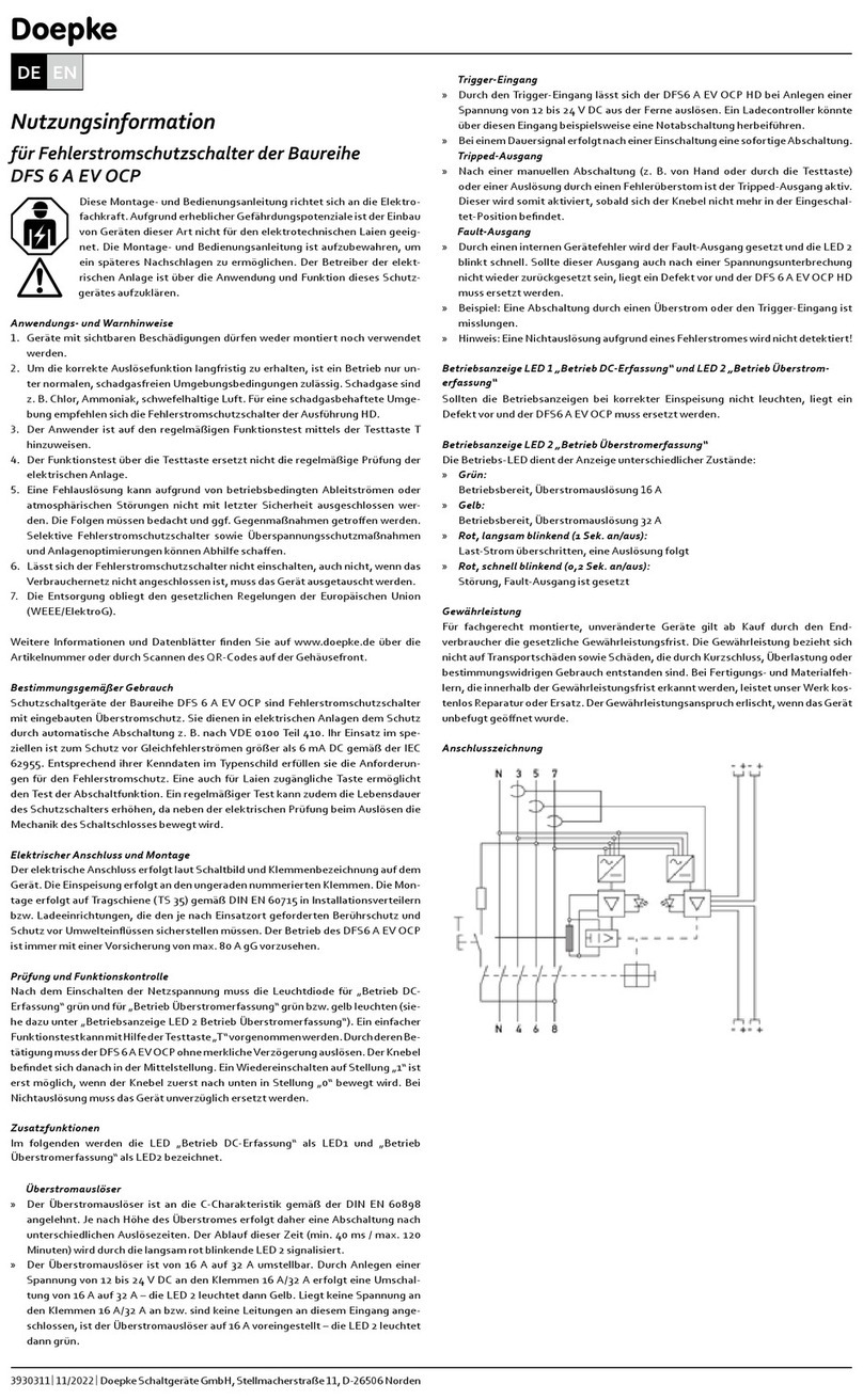
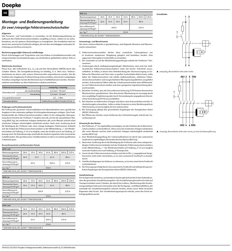
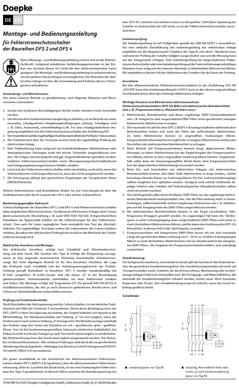
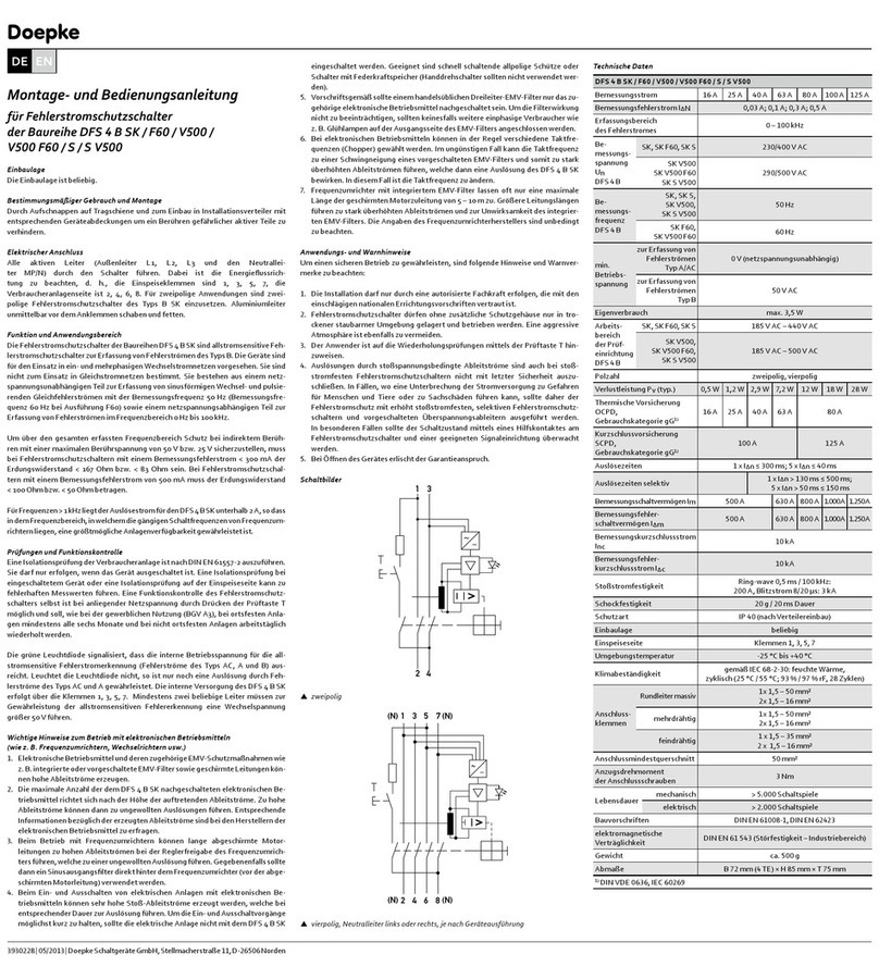
Schaltbilder
1 3
2 4
N 3 5 7
N 4 68
1 3 5 N
2 4 6N
Szweipolig Svierpolig,
Neutralleiter links
Svierpolig,
Neutralleiter rechts
Montage- und Bedienungsanleitung
für zwei-/vierpolige Fehlerstromschutzschalter
der Baureihe DFS F Audio
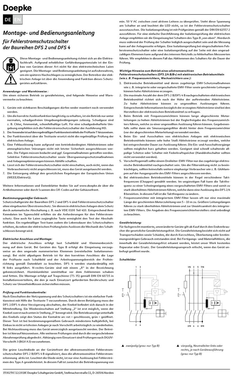
Diese Montage- und Bedienungsanleitung richtet sich an die Elektro-
fachkraft. Aufgrund erheblicher Gefährdungspotenziale ist der
Einbau von Geräten dieser Art nicht für den elektrotechnischen Laien
geeignet. Die Montage- und Bedienungsanleitung ist aufzubewahren,
um ein späteres Nachschlagen zu ermöglichen. Der Betreiber der
elektrischen Anlage ist über die Anwendung und Funktion dieses
Schutzgerätes aufzuklären.
Anwendungs- und Warnhinweise :
Um einen sicheren Betrieb zu gewährleisten, sind folgende Hinweise und Warn-
vermerke zu beachten:
1. Geräte mit sichtbaren Beschädigungen dürfen weder montiert noch verwendet
werden.
2. Um die korrekte Auslösefunktion langfristig zu erhalten, ist ein Betrieb nur unter
normalen, schadgasfreien Umgebungsbedingungen zulässig. Schadgase sind
z. B. Chlor, Ammoniak, schwefelhaltige Luft.
3. Der Anwender ist auf den regelmäßigen Funktionstest mittels der Prüftaste T
hinzuweisen.
4. Der Funktionstest über die Testtaste ersetzt nicht die regelmäßige Prüfung der
elektrischen Anlage.
5. Eine Fehlauslösung kann aufgrund von betriebsbedingten Ableitströmen oder
atmosphärischen Störungen nicht mit letzter Sicherheit ausgeschlossen werden.
Die Folgen müssen bedacht und ggf. Gegenmaßnahmen getroen werden.
6. Lässt sich der Fehlerstromschutzschalter nicht einschalten, auch nicht, wenn das
Verbrauchernetz nicht angeschlossen ist, muss das Gerät ausgetauscht werden.
7. Die Entsorgung obliegt den gesetzlichen Regelungen der Europäischen Union
(WEEE/ElektroG).
Weitere Informationen und Produkt-Datenblätter nden Sie auf www.doepke.de.
Bestimmungsgemäßer Gebrauch:
Schutzschaltgeräte der Baureihen DFS 2 und DFS 4 sind Fehlerstromschutzschal-
ter ohne eingebauten Überstromschutz. Sie dienen in elektrischen Anlagen dem
Schutz durch automatische Abschaltung z. B. nach VDE 0100 Teil 410. Entsprechend
ihrer Kenndaten im Typenschild erfüllen sie die Anforderungen für den Fehlerstrom-
schutz. Eine auch für Laien zugängliche Taste ermöglicht den Test der Abschaltfunk-
tion. Ein regelmäßiger Test kann die Lebensdauer des Schutzschalters erhöhen, da
neben der elektrischen Prüfung beim Auslösen die Mechanik des Schaltschlosses
bewegt wird.
Elektrischer Anschluss und Montage:
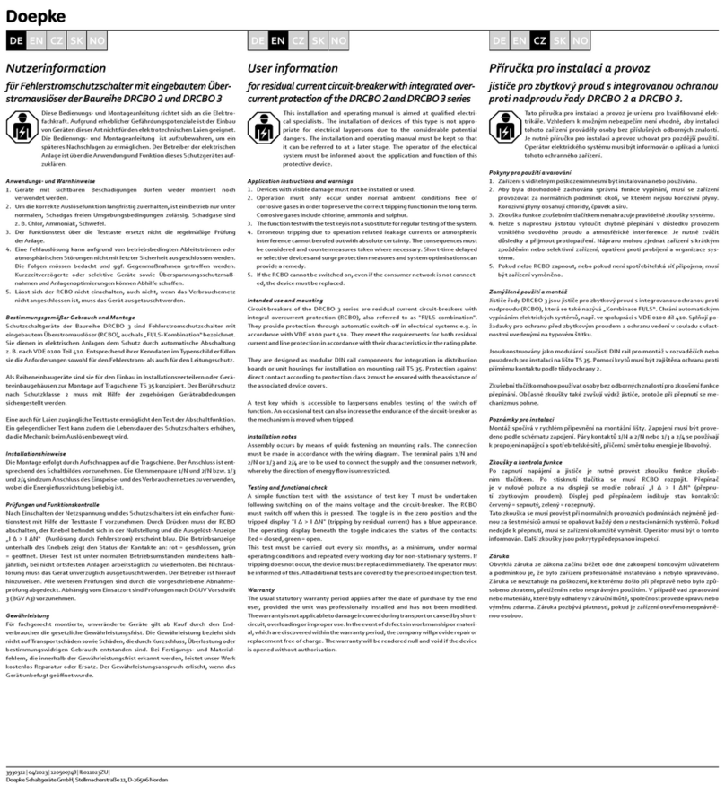
Der elektrische Anschluss erfolgt laut Schaltbild und Klemmenbezeichnung auf
dem Gerät. Bei nicht allpoligem Betrieb ist für den korrekten Anschluss die Lage der
Prüftaste nach Schaltbild und der Arbeitsspannungsbereich der Prüfeinrichtung ge-
mäß Datenblatt zu beachten. DFS 4 werden standardmäßig mit N links ausgeführt.
N-rechts-Geräte sind mit einem „R“ in der Bezeichnung gekennzeichnet. Die Monta-
ge erfolgt auf Tragschiene (TS 35) gemäß DIN EN 60715 in Installationsverteilern, die
den je nach Einsatzort geforderten Berührschutz und Schutz vor Umwelteinüssen
sicherstellen müssen.
Prüfung und Funktionskontrolle:
Nach Einschalten der Netzspannung und des Schutzschalters ist ein einfacher Funk-
tionstest mit Hilfe der Testtaste T vorzunehmen. Durch deren Betätigung muss der
DFS 2/DFS 4 ohne Verzögerung abschalten, der Knebel bendet sich danach in der
Mittelstellung. Ein Wiedereinschalten auf Stellung „1“ ist erst möglich, wenn der
Knebel zuerst nach unten in Stellung „0“ bewegt wird. Die Betriebsanzeige unterhalb
des Knebels zeigt den Status der Kontakte an: rot = geschlossen, grün = geönet.
Dieser Test ist bei bestimmungsgemäßem Gebrauch mindestens halbjährlich, bei
Einbau in nicht ortsfesten Anlagen je nach Vorschrift arbeitstäglich zu wiederholen.
Bei Nichtauslösung muss das Gerät unverzüglich ausgetauscht werden. Der Betrei-
ber ist hierauf hinzuweisen. Alle weiteren Prüfungen sind durch die vorgeschriebene
Abnahmeprüfung abgedeckt. Abhängig vom Einsatzort sind Prüfungen nach DGUV-
Vorschrift 3 (BGV A3) vorzunehmen. Die Isolationsprüfung ist mit Prüfgeräten ge-
mäß der DIN EN 61557-2 auszuführen.
Gewährleistung:
Für fachgerecht montierte, unveränderte Geräte gilt ab Kauf durch den Endverbrau-
cher die gesetzliche Gewährleistungsfrist. Die Gewährleistung bezieht sich nicht auf
Transportschäden sowie Schäden, die durch Kurzschluss, Überlastung oder bestim-
mungswidrigen Gebrauch entstanden sind. Bei Fertigungs- und Materialfehlern, die
innerhalb der Gewährleistungsfrist erkannt werden, leistet unser Werk kostenlos
Reparatur oder Ersatz. Der Gewährleistungsanspruch erlischt, wenn das Gerät un-
befugt geönet wurde.
Doepke
3930292 |11/2019 | Doepke Schaltgeräte GmbH, Stellmacherstraße 11, D-26506 Norden
DE EN
Recommendations for the power supply of audio systems in conjunction with the
DFS F Audio, with a view to improving sound:
The following recommendations must only be implemented by an authorised and
qualied electrical specialist, who is familiar with the applicable national installation
regulations. The recommendations exclusively refer to the circuit for connecting an
audio system. Priority should always be given to ensuring that electrical installations
are correctly implemented in line with the applicable installation regulations, over
any sound objectives.
»Use an outer conductor (L1, L2 or L3) that is used by as few other electrical
consumers (e.g. lights or household appliances) as possible.
»If possible, use a separate installation cable from the distribution installation
to the installation socket to which the audio system is connected. No further
electrical consumers should be connected to this circuit.
»When using multiple residual current circuit-breakers in a distribution installation,
the DFS F Audio should be connected on the input side, if possible directly, to the
connection cables from the meter board. Further residual current circuit-breakers
can then be connected on the input side, e.g. with suitable busbars.
»Connect the phase conductor to which your audio system is connected to the
output side (load side) of the DFS F Audio via a suitable overcurrent protective
device.
»Through use of a busbar fork, it is also possible to connect to the upper wiring level
for the DFS F Audio. This renes the sound image somewhat but does reduce the
volume a little.
»When connecting the neutral conductor to which your audio system is connected,
avoid having a lot of terminal positions in the neutral conductor path. If necessary,
it is possible to connect the neutral conductor directly to the neutral conductor
pole terminal on the output side (load side) of the DFS F Audio instead of to
the neutral conductor rail on the distribution board. This adds volume and
authenticity to the audio image without losing precision.
»If the installation cable to your audio system in the distribution installation needs
to be extended or connected to installation terminals, avoid using ferromagnetic
materials (e.g. copper-covered steel) as direct live parts. However, parts that
are not directly conductive that are used to mechanically secure electrical
conductors, e.g. clamping screws made from ferromagnetic material, have no
adverse eect on sound.
Hints:
»The audio image may initially seem rather unsettled following installation and
wiring work on the distribution board. This will subside after a few operating
hours.
»In comparison to standard residual current circuit-breakers, the DFS F Audio
provides a stable and clear audio image, without lessening the volume or
musicality. The sound is, however, aected by many factors relating to an audio
system’s power supply and, of course, by the components in an audio system and
can therefore vary.
»If mains lters are in place at the output side (load side) of the DFS F Audio, in
many cases, depending on the type of lter, it may be necessary to disconnect
them from the mains if the audio image is clearly dened but too thin.
Break-in time of the DFS F Audio:
»Immediately after it is rst commissioned, the audio image can seem more
lightweight, particularly in the low range.
»After around two to three operating hours, the audio image increasingly gains
in volume.
»The full potential of the sound is achieved after around 50–100 operating hours.
An audio system does not necessarily have to be active during this time.
»The residual current protection function of the DFS F Audio is of course available
immediately after installation and at all times.
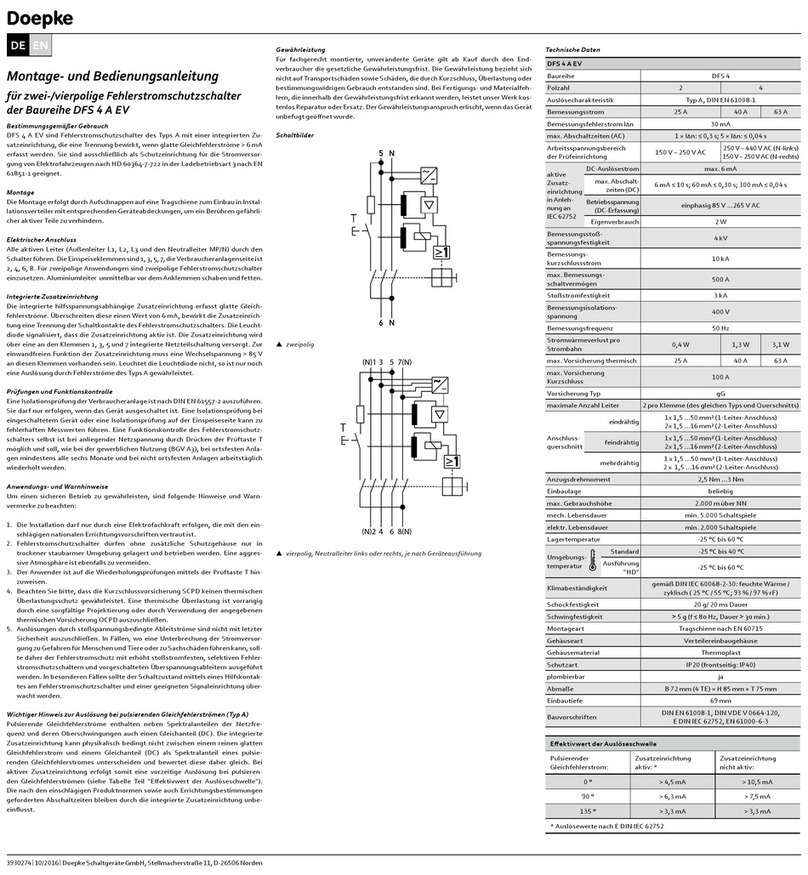
Wiring diagrams
1 3
2 4
N 3 5 7
N 4 68
1 3 5 N
2 4 6N
Stwo-pole Sfour-pole,
neutral conductor on
the left
Sfour-pole,
neutral conductor on
the right
Installation and operating instructions
for two-/four-pole residual current circuit-breakers
in the DFS F Audio series
These installation and operating instructions are aimed at qualied
electrical specialists. The installation of devices of this type is not
appropriate for electrical laypersons due to the considerable potential
dangers. These installation and operating instructions must be
retained, so that they can be referred to at a later stage. The operator
of the electrical installation must be informed about the use and
function of this protective device.
Application instructions and warnings
The following notes and warnings must be obser ved in order to ensure safe operation:
1. Devices with visible damage must not be installed or used.
2. Operation must only occur under normal ambient conditions free of corrosive
gases in order to preserve the correct tripping function in the long term.
Corrosive gases are chlorine, ammonia and sulphurous air, for example.
3. The user must be made aware of regular function testing using the test key T.
4. The function test with the test key is not a substitute for regular testing of the
electrical system.
5. Erroneous tripping due to operation related leakage currents or atmospheric
interference cannot be ruled out with absolute certainty. The consequences must
be considered and countermeasures taken where necessary.
6. If the RCCB cannot be switched on, or if the consumer network is not connected,
the device must be replaced.
7. Disposal is subject to the statutory regulations of the European Union (waste of
electrical and electronic equipment (WEEE)).
Further information and product data sheets can be found at www.doepke.de.
Intended use:
DFS 2 and DFS 4 series protective devices are residual current circuit-breakers
without integrated overcurrent protection. They provide protection through
automatic switch-o in electrical systems, e.g. in accordance with VDE 0100 part
410. They meet the requirements for residual current protection in accordance with
their characteristics on the name plate. The switch-o function can be tested using
a push-button which is also accessible to laypersons. Regular testing can increase
the endurance of the circuit-breaker, as the mechanism of the latch is moved when
tripped in addition to the electrical test.
Electrical connection and installation:
The electrical connection must be as shown in the wiring diagram and must comply
with the terminal designation on the device. If the device is to be operated without
using all poles, it is essential (in order to ensure the connection is correct) to observe
the position of the test key as per the wiring diagram and the operating voltage
range of the test circuit in accordance with the data sheet. DFS 4 devices have a
N-left design as standard. N-right devices have a ‘R’ in their designation. The device
must be installed on a mounting rail (TS 35) according to DIN EN 60715 in distribution
boards that have to ensure protection against direct contact (which may be required
depending on the location of use) and protection against environmental inuences.
Testing and functional check
A simple function test with the assistance of test key T should be carried out after
the mains voltage and the circuit-breaker are switched on. When the key is pressed,
the DFS 2/DFS 4 must disconnect without delay; the toggle is then in centre position.
Resetting to position ‘1’ is only possible if the toggle has rst been moved down to
position ‘0’. The operation indicator beneath the toggle indicates the status of the
contacts: red = closed, green = open.
This test must be carried out at least every six months where the device is used as
intended and must be repeated every working day for non-stationary systems
according to the regulation. If tripping does not occur, the device must be replaced
immediately. The operator must be informed of this. All additional tests are covered
by the prescribed acceptance test. Tests should be carried out according to DGUV
Regulation 3 (BGV A3) depending on the location. The insulation test should be
carried out using test devices according to DIN EN 61557-2.
Guarantee
All professionally installed, unaltered devices are covered by warranty during the
statutory guarantee period from the day of purchase by the end user. The guarantee
is not applicable to damage incurred during transport or caused by short-circuit,
overloading or improper use. Should any defects in workmanship or material
be discovered within the warranty period, the company will provide repair or
replacement free of charge. The warranty will be rendered null and void if the device
is opened without authorisation.
Doepke
3930292 |11/2019 | Doepke Schaltgeräte GmbH, Stellmacherstraße 11, D-26506 Norden
DE EN
This manual suits for next models
4
Table of contents
Languages:
Other Doepke Circuit Breaker manuals

Doepke
Doepke DFS 4 Series User manual

Doepke
Doepke DFS 4 A EV User manual

Doepke
Doepke DFS 4 NA Series User manual

Doepke
Doepke DMCB 2 Series User manual

Doepke
Doepke DFS 4 B SK series User manual

Doepke
Doepke DFL 8 B SK Series User manual

Doepke
Doepke DFS2 025-2/0,03-B SK User manual

Doepke
Doepke DFS 2 User manual

Doepke
Doepke DRCCB 5 Series User manual

Doepke
Doepke DFS 4 Series User manual