Fonrich FR-DCBS-AFC4C User manual

User Manual
Version 1.1
Arc Fault Protection Box FR-DCBS-AFC4C
Scan code to learn more
Fonrich (Shanghai) New Energy Technology Co., Ltd.
Add: 1st Floor, Building 5, No.999 Jiangyue Road, Minhang District,Shanghai
Web: www.fonrich.com
Tel:+86 21 61679671
Email: [email protected]
-DCBS-AFC4C

Fonrich New Energy Technology Co., Ltd.
1
Table of Contents
Table of Contents........................................................................................................................1
Preface........................................................................................................................................ 3
1 Safety Precautions....................................................................................................................4
2 Product Overview.................................................................................................................... 6
2.1 Description........................................................................................................................6
2.2 Appearance....................................................................................................................... 7
2.3 Principles of Design..........................................................................................................7
2.3.1 Schematic Diagram....................................................................................................7
2.3.2 Work principle........................................................................................................... 8
2.4 Arc alarm strategy.............................................................................................................9
2.4.1 Arc mode....................................................................................................................9
2.4.2 Arc alarm strategy......................................................................................................9
2.4.3 Arc alarm time........................................................................................................... 9
2.5 Inside Components........................................................................................................... 9
3 Installation............................................................................................................................. 10
3.1 Scope of Delivery........................................................................................................... 10
3.2 Requirements for Installation......................................................................................... 10
3.3 Drilling Diagram.............................................................................................................11
3.4 Procedure........................................................................................................................ 11
4 Electrical Connection.............................................................................................................13
4.1 DC Terminals..................................................................................................................13
4.2 AC Terminals(Single-phase three-wire connection)...................................................... 14
4.3 AC Terminals(Three-phase four-wire connection)........................................................ 15
5 Operation............................................................................................................................... 16
5.1 Checking before Operation.............................................................................................16
5.2 Operation........................................................................................................................ 16
5.3 Clearing the Arc Alarm.................................................................................................. 16
6 APP Connection.....................................................................................................................17
6.1 Download........................................................................................................................17
6.2 Connection......................................................................................................................17

Fonrich New Energy Technology Co., Ltd.
2
6.3 Status Interface............................................................................................................... 18
6.3.1 Design of the status interface...................................................................................18
6.3.2 Contact Status.......................................................................................................... 18
6.3.3 Arc Threshold (Range 1-127)..................................................................................18
6.3.4 Arc Alarm Times (Range 1-10)...............................................................................19
6.3.5 Arc Mode................................................................................................................. 19
6.3.6 Arc IAT (Range1-4)................................................................................................ 20
6.3.7 Arc CAT (Range15-60)........................................................................................... 20
6.4 Setting Interface..............................................................................................................20
6.4.1 Design of the setting interface................................................................................. 20
6.4.2 WIFI.........................................................................................................................21
6.4.3 Notification Email Address..................................................................................... 21
6.4.4 Software Related......................................................................................................21
7 Appendix................................................................................................................................22
7.1 Revision Log...................................................................................................................22
7.2 Contact Us...................................................................................................................... 22

Fonrich New Energy Technology Co., Ltd.
3
CAUTION
Preface
Instruction
This user manual describes introduction, installation, electrical connection and
operation in detail for FR-DCBS-AFC4C users. Before installing and operating of the
equipment, you should read and understand all the instructions and be familiar with
the relevant safety in relevant paragraphs.
Target Group
This user manual is intended for operators and end users.
Signs
The following signs may appear in this article, and their meanings are as follows.
Signs
Instructions
Indicates a hazardous situation which,if not avoided, will result
in death or serious injury.
Indicates a hazardous situation which,if not avoided, could
result in death or serious injury.
Indicates a hazardous situation which,if not avoided, could
result in minor or moderate injury.
Indicates a situation which,if not avoided, can result in property
damage.
It is not safety warning information, and does not involve
personal, equipment and environmental damage.
Note
Protrudes important or critical information, best practices, tips,
etc.
It is not safety warning information, and does not involve
personal, equipment and environmental damage.
WARNING
DANGER
NOTICE

Fonrich New Energy Technology Co., Ltd.
4
1 Safety Precautions
To prevent personal injury and property damage, read this section carefully and
observe all safety information at all times.
Requirements of operators
Operators must have the following skills:
Knowledge of how an arc fault production box works and is operated.
Training in how to deal with the dangers and risks associated with installing,
using electrical devices and installations.
Knowledge of and compliance with this document and all safety information.
Installation
Disconnect the product form voltage sources and make sure it cannot be
reconnected before working on the device.
Please do not touch the other parts inside in addition to the terminals during the
installation process.
Please read this user manual carefully before installation. If the equipment is
damaged resulting from violation of the regulations specified in this document,
our company has the right not to guarantee the quality.
The distance between FR-DCBS-AFC4C and the object should meet the
conditions.
Electrical connection
Before electrical connection, please make sure that FR-DCBS-AFC4C is not
damaged and in a safe state, otherwise it may cause electric shock or fire.
Touch the cables of the PV array on the insulation only.
All electrical connections must meet the electrical standards of the country or
region where they are located.
Please use the indicated electric wire and electric cable. Using electric wire and
electric cable with no sufficient capacity or with no correct connection method
will lead to machine breakdown, machine fire or electric shock.

Fonrich New Energy Technology Co., Ltd.
5
Operation
FR-DCBS-AFC4C has high voltage during operation, which may cause electric
shock or death in severe cases. Please operate strictly in accordance with the
safety precautions listed in this manual and other related documents.

Fonrich New Energy Technology Co., Ltd.
6
2 Product Overview
2.1 Description
FR-DCBS-AFC4C is solar AFCI (Arc Fault Circuit Interrupter), which is mainly
used in small sizes of distributed PV system.
Functions
Its main function is to detect the arc fault of the PV
strings and make the string cables in the state of no
current when the arc fault occurs. In addition, users can
remotely monitor the state of the product by the mobile
phone APP, such as arc alarm, relay contact, current, etc.
Features
•1-4 PV strings each box supports
•Arc fault detecting of each PV string
•Fonrich IP technology to self-adapt with different inverters
•UL 1699B 2018 conformity
•The protection arc sensitivity is adjustable
•WiFi internet connection, email alarm notification
Application
FR-DCBS-AFC4C is mainly used in small sizes of distributed PV system, such
as <10KW residential solar system. The system consists of PV strings, arc fault
protection box, inverter and grid, as shown in the figure below.
Typical Application of AFC4C
Fonrich New Energy Technology Co., Ltd.
7
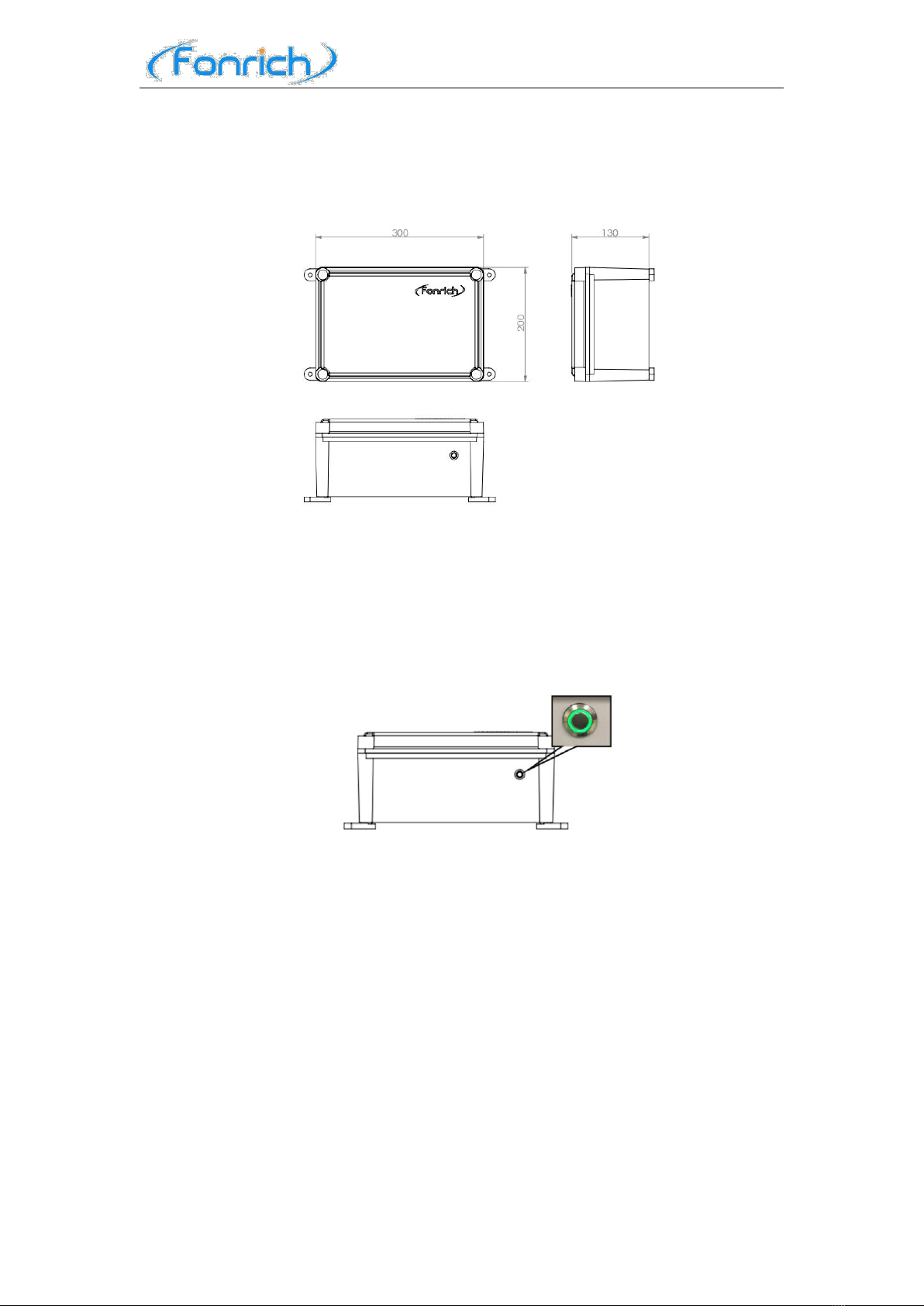
2.2 Appearance
Dimensions(mm)
LED Signal
There is a LED in the front of the FR-DCBS-AFC4C,which indicates the
operating state of the product.
The green LED is on : The product is operating normally .
The green LED is off : The product is not operating or the arc faults occurred .
2.3 Principles of Design
2.3.1 Schematic Diagram
DC side: 4 PV strings are connected to the DC input terminals of the product. After
passing through the arc fault detectors, the DC output terminals of the product are
connected to the input terminals of the inverter.
AC side: The output terminals of the inverter are connected to the AC input
terminals of the product, and after passing through the AC relay, the AC output
terminals of the product are connected to the input terminals of the grid.

Fonrich New Energy Technology Co., Ltd.
8
Single-phase three-wire
Three-phase four-wire
2.3.2 Work principle
If the arc fault is detected, the product will issue an alarm signal by the indicator
and Email. At the same time, the AC relay will be driven to break off the AC circuit
between the inverter and the grid. So that the inverter will stop working to ensure that
the DC circuit is in the state of no current. After 2 minutes, the AC relay will be
driven to turn on the AC circuit and then the entire circuit resumes normal operation.
Fonrich New Energy Technology Co., Ltd.
9
2.4 Arc alarm strategy
2.4.1 Arc mode
We divide the arcs into Instantaneous Arc and Continuous Arc.
Instantaneous Arc
The arc duration does not exceed the Instantaneous Arc Time (IAT), and there is
no arc occurring again within the Continuous Arc Time (CAT).
Continuous Arc
The arc duration exceeds the IAT, or the arc duration does not exceed the IAT,
but the arc occurs again within the CAT.
2.4.2 Arc alarm strategy
1. Instantaneous arc alarm
If the arc intensity of any channel exceeds the channel alarm threshold, an arc
alarm will be generated.
2. Continuous arc alarm
The product does not alarm when instantaneous arc is detected, but only when
continuous arc is detected.
2.4.3 Arc alarm time
The calculation method of the arc alarm times of the channel: When an arc alarm
occurs in any channel, the number of arc alarm times increases by 1. When arc faults
occur in several channels at the same time, the number of arc alarm times only
increases by 1. The product will automatically restart after 2 minutes.
However, when the arc alarm times is up to the value of the arc alarm time, the device
must be restarted manually.
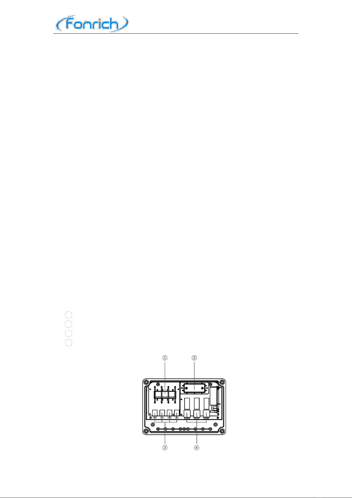
2.5 Inside Components
Description
1Arc Fault Detector : Detect real-time the arc in the PV strings.
2Main Control : Control the state of the product.
3DC Terminals : PV strings input and output terminals.
4AC Terminals : Inverter input and output terminals.

Fonrich New Energy Technology Co., Ltd.
10
3 Installation
3.1 Scope of Delivery
Check the scope of delivery for completeness and any externally visible damage
before installation. Contact your distributor if the scope of delivery is incomplete or
damaged.
Product and accessories
3.2 Requirements for Installation
Do not install the product in areas containing highly flammable material or
grass.
Do not install the product in potentially explosive atmospheres.
Disconnect the product from voltage sources and make sure it cannot be
reconnected before working on the device.
Do not install the product in the area where can be touched unintentionally.
Take wall-mounted installation as an example to introduce:
A solid support surface must be available.
The ambient temperature range is -30℃ ~ +60℃.
The protection level of FR-DCBS-AFC4C is IP65, and it can be used in both
indoor and outdoor environments.
The product should be installed such that the LED signal can be read off
Position
Quantity
Designation
①
1
Arc Fault Protection Box
②
4
Fixture
③
4
Cylindrical screw
Fonrich New Energy Technology Co., Ltd.
11
without difficulty.
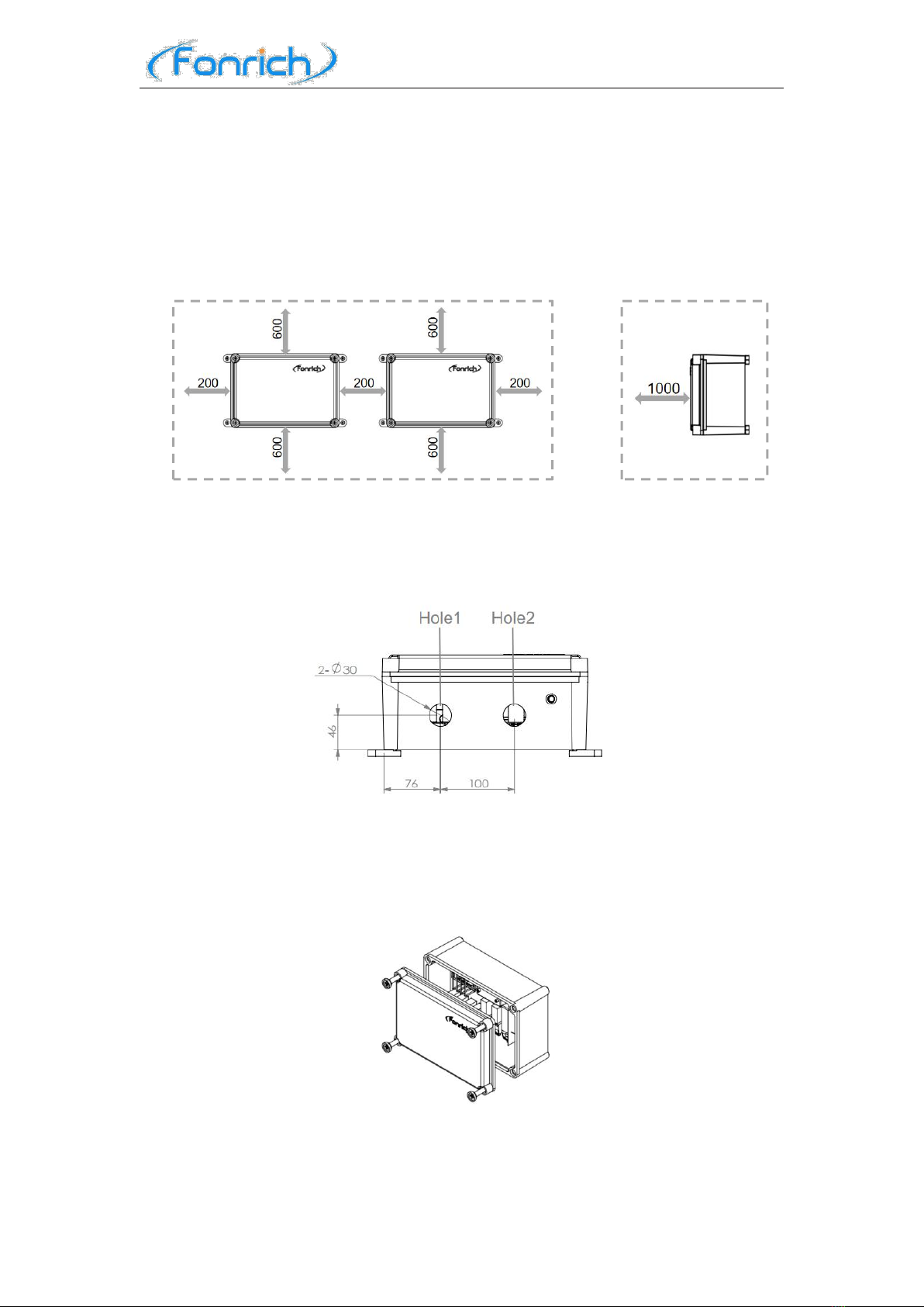
Recommended installation clearances
If you maintain the recommended clearances,adequate heat dissipation will be
ensured. Thus,you will prevent power reduction due to excessive temperature.
Maintain the recommended clearances to walls as well as to other products or
objects.
(Dimensions in mm)
3.3 Drilling Diagram
Users can drill the bore holes according to their own needs.The size diagram of
the holes is as follows.
3.4 Procedure
1) Remove the four screws on the product cover using a flat-blade screwdriver,
and then remove the front panel.
2) Place the four fixtures under the four corners of the product bottom, put the
screws into the holes.And then screw the four fixtures to the product using the
screwdriver.

Fonrich New Energy Technology Co., Ltd.
12
3) Place the product vertically on the wall and use the screws to attach the four
fixtures of the product to the wall.
Note :Install the front panel after completing the electrical connections in the
fourth chapter.

Fonrich New Energy Technology Co., Ltd.
13
4 Electrical Connection
Before electrical connection, please make sure that FR-DCBS-AFC4C is not
damaged and in a safe state, otherwise it may cause electric shock or fire.
Touch the cables of the PV array on the insulation only.
All electrical connections must meet the electrical standards of the country or
region where they are located.
Please use the indicated electric wire and electric cable. Using electric wire and
electric cable with no sufficient capacity or with no correct connection method
will lead to machine breakdown, machine fire or electric shock.
4.1 DC Terminals
Connect the product, inverter and PV strings through the DC terminals as shown
in the figure below.
`
Procedure
1) Strip the insulation of PV string cables.
L is the reference value of the exposed length of the conductor of the DC cables.
The length of L is recommended to be 8-10mm.
2) Pull up the handle of the DC terminals.

Fonrich New Energy Technology Co., Ltd.
14
3) Insert the stripped conductor section into the connection port.
4) Press down the handle of the DC terminals.
4.2 AC Terminals(Single-phase three-wire connection)
Connect the product, inverter and grid through the AC terminals as shown in the
figure below.
Procedure
1) Strip the insulation of the cables.
L is the reference value of the exposed length of the conductor of the AC cables.
The length of L is recommended to be 9-11mm.
2) Pull up the handle of the AC terminals.
Fonrich New Energy Technology Co., Ltd.
15
3) Insert the stripped conductor section into the corresponding connection port.
4) Press down the handle of the AC terminals.
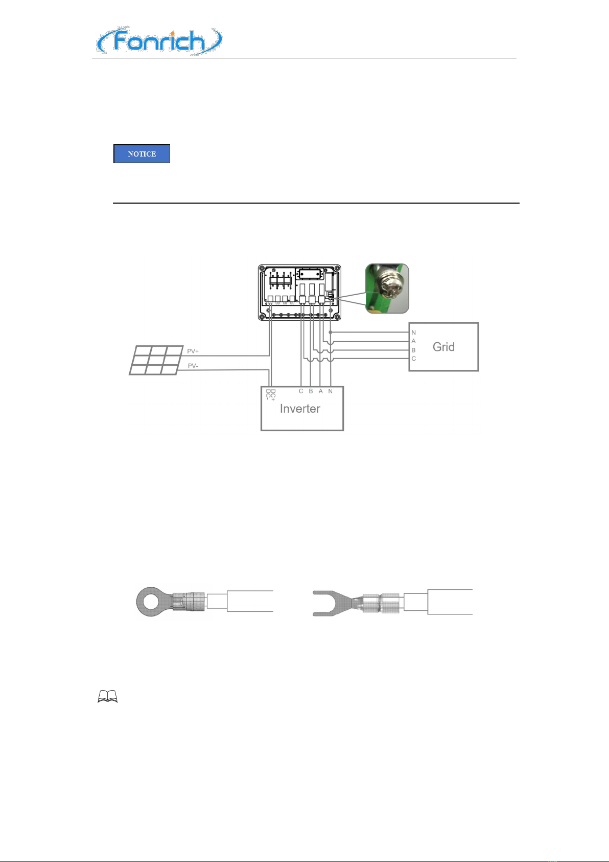
4.3 AC Terminals(Three-phase four-wire connection)
When wiring three-phase four-wire, the silkscreen mark of the AC terminals is
not applicable, please follow the instructions for wiring.
Connect the product, inverter and grid through the AC terminals and N terminal
as shown in the figure below.
Procedure
1) Strip the insulation of the cables.
2) Pull up the handle of the AC terminals.
3) Insert the stripped conductor section of the cables into the corresponding
connection port.
4) Press down the handle of the AC terminals.
5) Insert the stripped conductor section of the cables into the OT terminal or
U-shaped terminal, and then connect it to the N terminal.
------THE END
Note: Cover the front panel of the product and fix it firmly with screws.

Fonrich New Energy Technology Co., Ltd.
16
5 Operation
5.1 Checking before Operation
In order to ensure the normal operation of the arc safety protection box, a
pre-operation inspection is required.
The product must be correctly installed.
All cables must be correctly connected.
5.2 Operation
Perform power-on operation to turn on the FR-DCBS-AFC4C.
The green indicator is on, and the product is in normal operation.
5.3 Clearing the Arc Alarm
When the green indicator is off, it proves that arc fault has occurred.
Press the indicator to clear the arc alarm.Then the green indicator will light again
and the product will work .
Fonrich New Energy Technology Co., Ltd.
17
6 APP Connection
FR-DCBS-AFC4C has a matching mobile phone APP(FR-DCBS-AFC4x). Users
can connect the FR-DCBS-AFC4C to APP by Bluetooth.
6.1 Download
IOS users can download the APP(FR-DCBS-AFC4x) in the APP Store
Users can scan the following QR code to download the matching APP or
download it on the FONRICH website (www.fonrich.com).
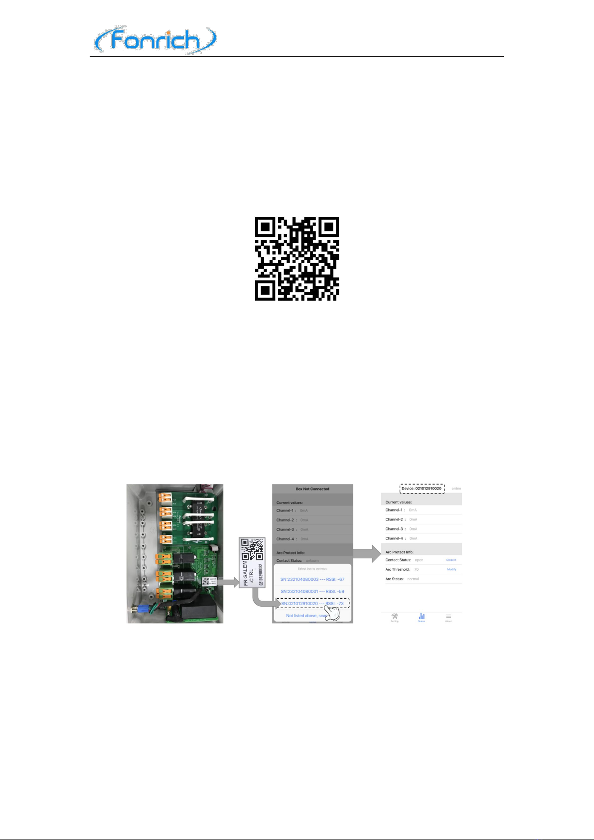
6.2 Connection
Take the product coded 021012910020 as an example.
Procedure
1. Find the 021012910032 on the label of the main control.
2. Turn on the Bluetooth and the APP of the mobile phone,and select the serial
number 021012910032 to be connected.
If the product is not retrieved, you can click[Not listed above, scan again] .
3. When the APP is successfully connected to the product, it will enter the
Status Interface.
Fonrich New Energy Technology Co., Ltd.
18
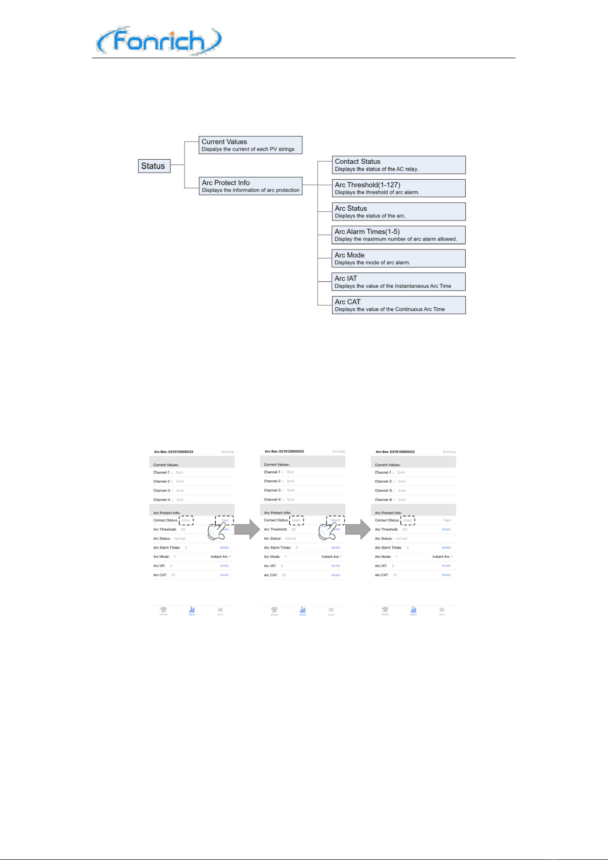
6.3 Status Interface
6.3.1 Design of the status interface
6.3.2 Contact Status
1) Click on [Trig it] when the contact status is [close].
2) The product makes a clicking sound at this moment, and the contact status is
changed to [open].
3) Click on [Close it] when the contact status is [open].
4) The product will make a clicking sound at this moment,and the contact status
is changed to [close].
6.3.3 Arc Threshold (Range 1-127)
1) Clink on [Modify].
2) Enter the desired parameter [40]and select [OK] (Take 40 as an example).
3) This parameter is modified to [40].

Fonrich New Energy Technology Co., Ltd.
19
6.3.4 Arc Alarm Times (Range 1-10)
1) Clink on [Modify].
2) Enter the desired parameter [5]and select [OK] (Take 5 as an example).
3) This parameter is modified to [5].
6.3.5 Arc Mode
1) Clink on [ ].
2) Select the desired arc alarm mode.
Table of contents
Other Fonrich Circuit Breaker manuals

Popular Circuit Breaker manuals by other brands

Topgreener
Topgreener TGWF215U2A installation instructions

Vimar
Vimar ELVOX 40636 instruction sheet

Eaton
Eaton NZM1-XMV Instruction leaflet

Eaton
Eaton XTCERENCONTACTD DILM40 65XCT Series Instruction leaflet

Eaton
Eaton Cutler-Hammer W-VAC Instructions for installation, operation and maintenance

LEGRAND
LEGRAND DMX-SP 4000 manual


