Shihlin electric BW-2000 User manual
Distributor
MOTOR CONTROL (CONTACTOR/ MS/ MMS), CIRCUIT BREAKER (MCCB/ ELCB/ EMCCB/ MCB), AIR CIRCUIT BREAKER, AUTOMATIC
TRANSFER SWITCHES (Panel Board Type/ Residential Unit Use), SURGE PROTECTIVE DEVICE, LOW VOLTAGE POWER CAPACITORS,
SMART METER, INVERTER
Breaker & switchgears overseas sales dept.
3F, No.9, Sec. 1, Chang-an E. Rd., Zhongshan Dist., Taipei City 10441, Taiwan
T. +886-2-2541-9822 F. +886-2-2581-2665
e-mail. [email protected]
http://circuit-breaker.seec.com.tw
Headquarter
16F, No.88, Sec. 6, Zhongshan N. Rd., Shilin Dist., Taipei City 11155, Taiwan
T. +886-2-2834-2662 F. +886-2-2836-6187
http://www.seec.com.tw
http://circuit-breaker.seec.com.tw
http://www.seec.com.tw

INSTRUCTIONS

AIR CIRCUIT BREAKER
Contents
Specication
1. Introduction
1.1 Purposes
1.2 Type designation
1.3 Classication
1.4 Conditions of Use
2. Structure specications
3. Intelligent controller
3.1 Function comparison table
3.2 Protection Parameter
3.2.1 Overload Long time delay protection characteristics
3.2.2 Short-circuit short time delay protection characteristics
3.2.3 Short-circuit instantaneous protection characteristics
3.2.4. Unsymmetrical earthing / leakage protection characteristics
3.2.5 Load monitoring protection characteristics
3.2.6 Phase failure protection characteristics
3.2.7 Other functions
4. Characteristics curves
4.1 Overload, short-circuit, instantaneous protection
4.2 Earthing protection
4.3 Leakage protection
5. Accessories
5.1 Shunt-release, under-voltage release, Motor-driven, closing coil
5.2 Auxiliary contacts
5.3 Lock devices
5.4 Testing kit
6. Wiring
6.1 Control wire diagram
6.2 Secondary wire diagram
6.2.1 XSIC-A series intelligent controller
6.2.2 XSIC-P series intelligent controller
6.2.3 ATS Wiring Diagram
7. Outline and installation dimensions
7.1 Draw-out type outline
7.2 Fixed type outline
7.3 Compartment Hole Drilling Dimensions and Mounting Hole Distance
8. Mounting, usage and maintenance
8.1 Mounting
8.2 Intelligent Controller Usage
8.2.1 Panel Schematic Diagram
8.2.2 HMI Instruction
8.2.3 Setting, query and testing methods and system clock setup
8.3 Instruction of draw in/out of ACB main body
8.4 Maintenance
9. Commonly Observed Faults and Trouble-shooting
1
2
2
2
2
2
3
4
5
5
5
6
6
7
8
9
9
12
12
12
13
14
14
14
15
17
17
17
18
18
18
19
20
20
24
26
27
27
27
27
28
30
35
35
36

ACB-OB
1
INSTRUCTIONS
HS HN HS HN HS HN
5000
3 / 4
6300
3 / 4
3P
4P
3P
4P
Endurance
Frame size
Model
Rated current of N pole
Number of pole
Rated Impulse withstand
voltage(Uimp)
Rated insulation
voltage (Ui)
Rated operation voltage(Ue)
Rated current (In)
AF
A
V
V
kA
Type
Rated breaking capacity IEC60947-2Dimension
Connection
With
maintenance 20000 20000 20000 20000 20000 20000 8000
Horizontal
435 x 842
x 505 435 x 960
x 505
AC 400V 8000 8000 6500 6500 5000 5000 500
AC 690V 3000 3000 2500 2500 2500 2500
100% In
50 / 40
75 / 48
78 / 50
80 / 50
85 / 55
150 / 95
50
50
55 / 55
78 / 78
82 / 82
85 / 85
90 / 90
155 / 155
55
65
65 / 50
85 / 55
90 / 60
100 / 65
100 / 65
170 / 110
65
65
65 / 65
90 / 90
95 / 95
100 / 100
105 / 105
180 / 180
65
85
65 / 50
85 / 55
90 / 60
100 / 65
100 / 65
170 / 110
65
65
75 / 75
90 / 90
95 / 95
100 / 100
105 / 105
180 / 180
75
85
75 / 65
100 / 100
110 / 100
120 / 100
130 / 130
200 / 200
100
Without
maintenance 10000 10000 10000 10000 10000 10000 2500
AC 690V
*AC 440V
*AC 415V
AC 400V
*AC 380V
*AC 220V
AC 690V
AC 400V
AC1000
50/60Hz
12
6300
HS
BW-6300
Horizontal
402 x 537 x 377
BW-4000
4000
3200/4000
AC1000
50/60Hz
12
3 / 4
100% In
430 x 465 x 466
430 x 580 x 466 435 x 926 x 492
402 x 422 x 377
Electrical
Mechanical
Icu / Ics
(kA)
Icw
(kA)
@1 sec
Drawout
type
H x W x L
Fixed
type
H x W x L
AC1000
50/60Hz
12
3 / 4
100% In
BW-2000
2,000
630/800/1000/
1250/1600/2000
AC400, 690V
50/60Hz
AC400, 690V
50/60Hz
AC400, 690V
50/60Hz
AC400, 690V
50/60Hz
Horizontal
430 x 405 x 421
430 x 500 x 421
402 x 362 x 332
402 x 455 x 332 402 x 537 x 332
402 x 422 x 332
AC1000
50/60Hz
12
3 / 4
100% In
BW-3200
3200
2000/2500/3200
Horizontal
430 x 465 x 421
430 x 580 x 421
A/P A/P A/P A/P A/P A/P A/P A/PElectronic tripping device
Note: "*" is for reference

ACB-OB
2
AIR CIRCUIT BREAKER
1.3 Classication
■Mounting type: Draw out type, xed type
■Operation mode: Electric and manual operation
■Number of poles: 3 and 4
■Tripping categories: Intelligent controller, under-voltage instantaneous (or delay) release, and shunt release
■Intelligent controller can be divided into two types based on functions: XSIC-A and XSIC-P
■Under-voltage release has instantaneous and delay types.
1.4 Conditions of Use
■Ambient temperature: -5oC~40oC
Note: (1) If the minimum working condition is -10oC or -25oC, please notify us when ordering the product.
(2) If the maximum working condition exceeds +40℃or the minimum is less than -25oC, please discuss with the
sales representative.
■The product cannot be installed at places above 2000 altitute.
■Atmospheric conditions: Relative humidity could not exceed 50% when the surrounding temperature is +40oC. For
lower temperature, the relative humidity can be higher. The average maximum relative humidity for the month
with the highest humidity is 90%, and the average lowest temperature of that month is +25oC. Please consider the
possibility of frosting on the surface of the product due to temperature change.
■Pollution level: 3
■Mounting categories: For circuit breakers with rated voltage 690V or below, under-voltage release coils and power
transformer level 1 coils, the mounting type is IV. For auxiliary circuits and control circuits, the mounting type is III.
■Mounting conditions: Consult this manual for circuit breaker installation.
1. Introduction
1.1 Purposes
The rated voltages of BW series air circuit breakers (referred to as circuit breakers) are rated voltage AC400V, 690V,
50/60HZ. The rated current is from 630 to 6300A. It's used for distributing power and protecting circuits in the electrical
distribution system is protected from overloading, voltage shortage, short circuit, earthling, and other hazardous faults.
The circuit breaker has multiple intelligent protection functions available for selection. The protective actions have a
high precision for preventing unnecessary power failure, closing power supply much more reliable.
1.2 Type Designation
BW
Circuit breaker poles
(4-4 poles, 3-3 poles)
Circuit breaker pole codes
(HS for standard, HN for high breaking)
Circuit breaker frame size
(2000, 3200, 4000*, 6300)
All purpose circuit breakers

ACB-OB
3
INSTRUCTIONS
2. Structure Specications
1. Secondary circuit terminal (Fixed)
2. Cradle
3. Shutter
4. Handle
5. Secondary circuit terminal (movable)
6. Auxiliary contacts
7. Shunt release
8. Closing coil
9. Operation mechanism
10. Intelligent controller
11. Panel
12. Motor driven
10
11
1
3
4
2
5
6
7
8
9
12
ACB-OB
4
AIR CIRCUIT BREAKER
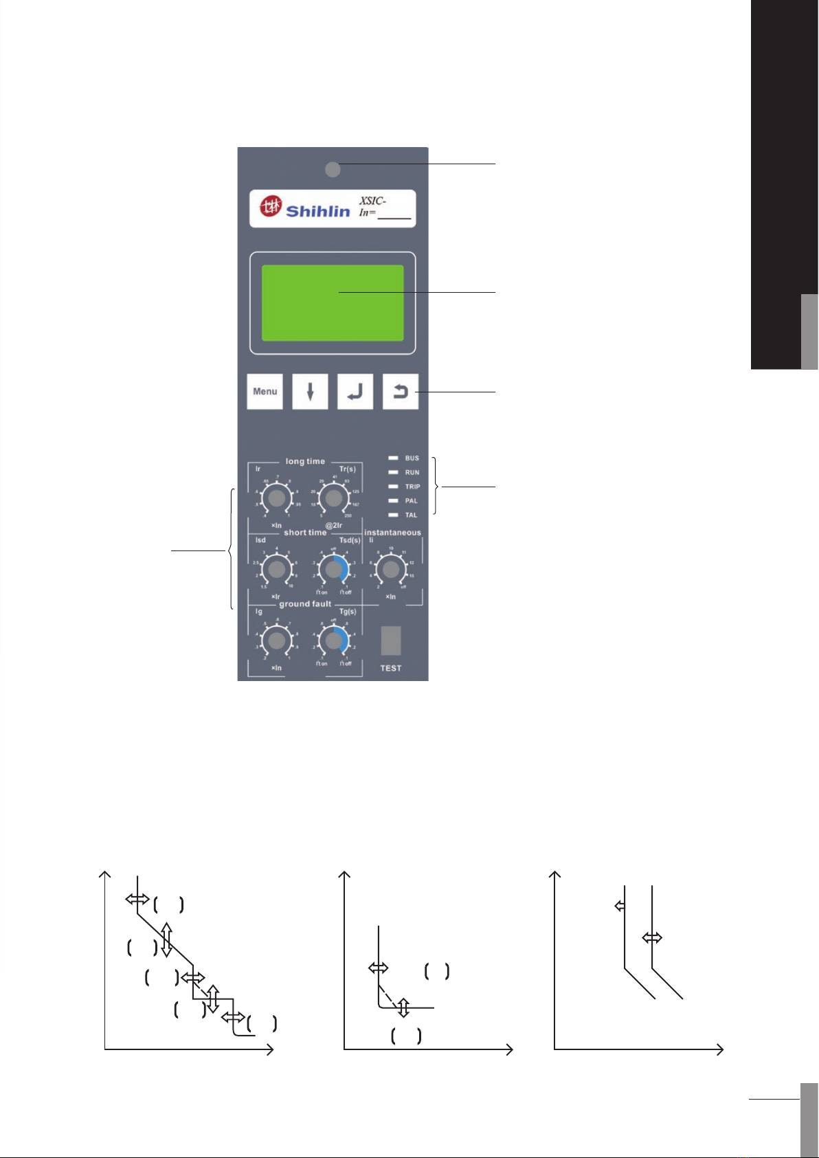
1. Reset button
2. LCD display
3. LED status indicator
4. Function buttons
5. Rotary protection setting
3. Intelligent Controller
Ir
Ii
Tr
Isd
Tsd
Setting
Instantaneous
tripping
Earthing
Ic2
Ic1
Earthing delay
Ig
Tg
1
2
4
3
5
ACB-OB
5
INSTRUCTIONS
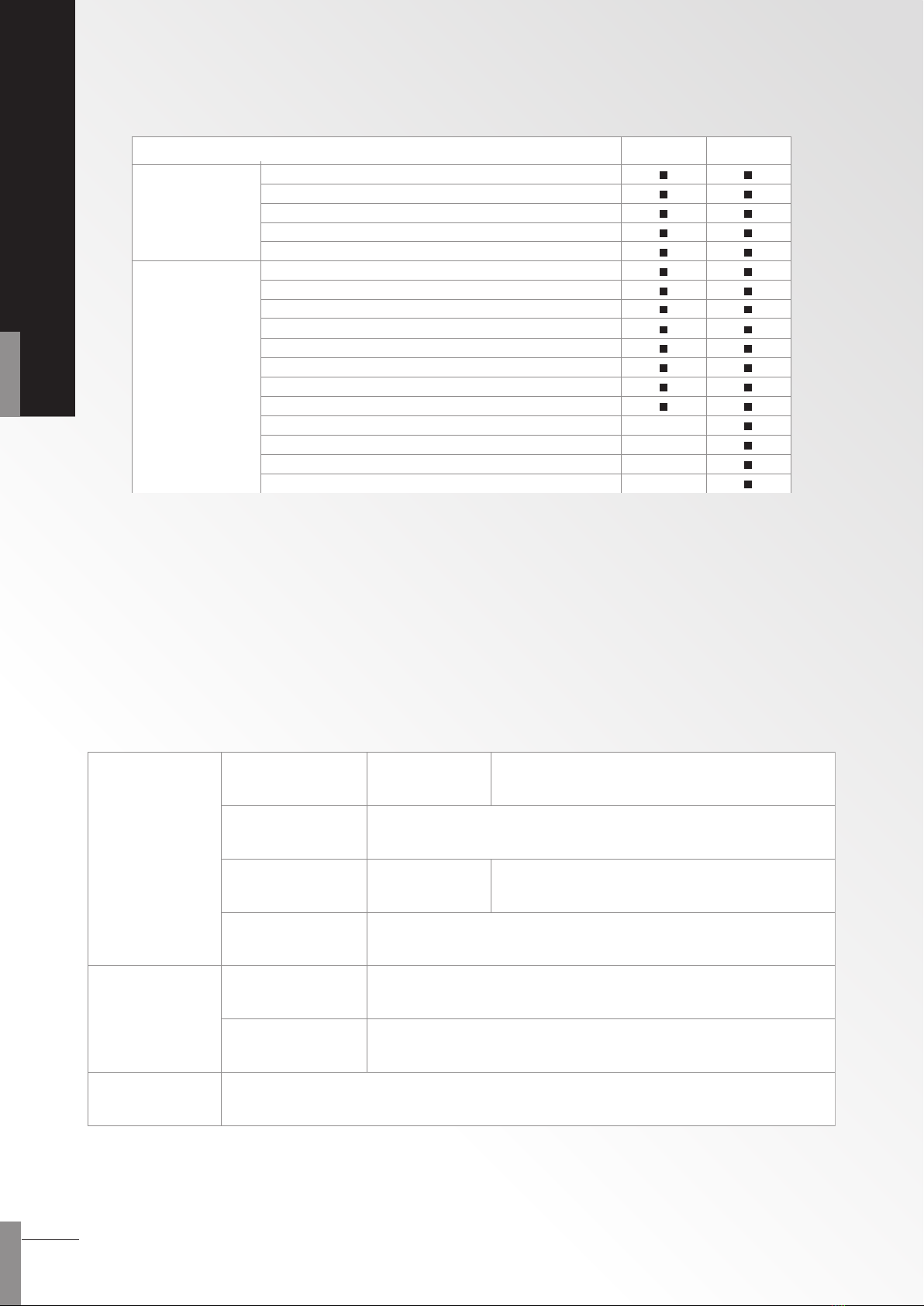
3.1 Function Comparison Table
3.2 Protection Parameter
3.2.1 Overload Long time delay Protection Characteristics
Overload long time delay protection has inverse time characteristics. The intelligent controller carries out
protection based on (I2-Ir2)t=3Ir2Tr.
Trcan be 5-10-20-29-41-83-125-167-250s. Techical parameters of overload long-delay protection characteristics of
the controllers are listed in Table 1.
Overload long-delay protection
Short-circuit, short-delay protection
Instantaneous protection
Earthing/leakage protection/None (Optional)
Phase failure protection
Current measurement
Imbalance current ratio measurement
Fault record functions
Thermal memory functions
MCR
Contact point wearing and machine lifespan indication
programming port
Temperature self-test
Voltage measurement
Load monitoring
Four-set signal output
Communication
Controller
Protection
function
Other
functions
XSIC-A XSIC-P
Adjusting steps
0.4-0.5-0.6-0.65-0.7-0.8-0.9-0.95-1
Ir =
(0.4~1) In
Current
setting value
Adjusting steps
5-10-20-29-41-83-125-167-250 (@2Ir)
Tr =
(5~250) s
Inverse
time delay
Released in 1.05 to 1.2Ir
Operation
characteristics
I2T
Operation
curve
100% or 50% (Suitable for 3P+N or 4P products)
Current
setting value
Same as protection characteristics of A, B, and C phases
Operation
characteristics
long time delay
N-phase
Protection
30 minute / o (Cut o the power of the controller for reset)
Thermal
memory function
Table1. Technical parameters of overload long time delay protection characteristics
Note: When the N-phase protection setting coecient is 50%, the setting value of N-phase protection would be 50% of phases A,
B and C.
For example, if the overload long-delay setting current is 1600A, the overload setting current for the N phase will be 800A.

ACB-OB
6
AIR CIRCUIT BREAKER
3.2.2 Short-circuit Short time delay Protection Characteristics
Intelligent controller's short-circuit Short time delay protection methods comprises inverse time protection and
denite time restriction protection.
1. Inverse time protection: When the fault current exceeds the present setting current value but is smaller than
the maximum setting short-circuit current (10Ir), the controller will carry out protection (10Ir)2*Tsd=I2*t
according to the inverse time curve. When the fault current exceeds the maximum setting short-circuit
current (10Ir), the controller will carry out delay protection according to the present delay setting value.
2. Definite time protection: When the fault current exceeds the present setting short-circuit current, the
controller will carry out delay protection according to the present delay setting value.
3. When overload long-delay setting time Tr = 5s or 10s, the short-circuit protection enforced setting will be
denite time protection (unadjustable).
Technical parameters of short-circuit short time delay protection characteristics are listed in Table 2.
3.2.3 Short-circuit Instantaneous Protection Characteristics
The operation time of short-circuit instantaneous protection (including the original breaking time of the circuit
breaker) should be less than 100ms. Parameters of the controller's short-circuit instantaneous protection
characteristics are listed in Table 3.
Table 2. Technical parameters of short-circuit short time delay protection characteristics
Table 3. Technical Parameters of Short-circuit short time delay Protection Characteristics
Note: When delay setting value is set to “I2 T ON”, the controller will carry out protection according to the inverse time method,
and the denite time function will automatically become invalid. When delay setting value is set to “I2 T OFF”, the
controller will carry out protection according to the denite time setting, and the inverse time function will automatically
become invalid.
Adjusting steps:
2-4-6-8-10-11-12-15 + OFF
Ii =(2~15)In
Current
setting value
Operation
time
Tripped between 0.9 and 1.1Ir
Operation
characteristics
< 100ms(including the original break time of the circuit breaker)
instantaneous
Adjusting steps:
1.5-2-2.5-3-4-5-6-8-10
Isd =(1.5~10)Ir
Current
setting value
Adjusting steps:
I2 T on = 0.1-0.2-0.3-0.4(@10Ir)+OFF
I2 T off = 0.1-0.2-0.3-0.4
Tsd=(0.1~0.4)s
Time delay
setting value
Tripping between 0.9 and 1.1Isd
Operation
characteristics
I2 T / definite time
Operation
curve
15 minute / off ( Cut off the power of the controller for reset)
Short time delay
Thermal
memory function

ACB-OB
7
INSTRUCTIONS
3.2.4 Unsymmetrical Earthing / Leakage Protection Characteristics
Intelligent controller's earthing protection methods comprise inverse time protection and definite time
protection.
1. Inverse time protection: When the fault current exceeds the present setting current but is smaller than 5Ig, the
controller will carry out protection (5Ig)2*Tg=I2*t based on the inverse time curve. When fault current exceeds
5Ig, the controller will carry out protection based on the current delay setting value (which is the denite time).
2. Denite time protection: When the fault current exceeds the present setting earthing current, the controller will
carry out delay protection according to the present delay setting value.
Technical parameters of earthing/leakage protection characteristics of the controllers are listed in Table 4.
Table 4. Technical Parameters of Earthing/Leakage Protection Characteristics
Single-phase earthing protection is a metallic protection when fault current exceeds 800 ampere. This is generally applied
to neutral-point direct earthing system. There are two kinds of protection modes for the controller. One is the vector sum
mode of internal transformer (earthing protecting). The controller carries out protection according to the three-phase
current and neutral polar current vector. The number of poles of circuit breakers can be divided into three types, 3PT, 4PT,
and 3P+N. This method in general is suitable for a balanced load. It is not suitable for an imbalanced load or a motor load.
PEN
N
PE
N
PE
PE or PEN
ZCTZCT
ZCT
N
N
PE
Intelligent
controller Intelligent
controller
Intelligent
controller
Intelligent
controller
Intelligent
controller
Intelligent
controller
3PT 4PT 3P+N
CT
Mode 1 External transformer
The transformer is ZCT1.
Mode 2 External transformer
The transformer is ZCT1.
Mode 3 External transformer
The transformer is ZT100.
Adjusting steps:
0.2-0.3-0.4-0.5-0.6-0.7-0.8-0.9-1.0
Adjusting steps:
I2 T on = 0.1-0.2-0.4-0.8(@5Ig)+OFF
I2 T off = 0.1-0.2-0.3-0.4
Ig = (0.2~1) In
Tg = (0.1~0.8) s
Tripped between 0.9 and 1.1Ir
I2 T / definite time
Earthing
protection
Leakage
protection
Adjusting steps:
0.5-1-2-3-5-7-10-20-30
Adjusting steps:
0.06-0.1-0.2-0.3-0.4-0.6-0.8-1.0 + OFF
If = (0.5~30) A
Tf = (0.06~1.0) s
Tripped between 0.9 and 1.1 x If
Definite time
Current setting value
(Minimum value = 160A)
Time delay
setting value
Operation
characteristics
Operation
curve
Current
setting value
Time delay
setting value
Operation
characteristics
Operation
curve

ACB-OB
8
AIR CIRCUIT BREAKER
Another is transformer mode of external leakage. The controller gets the output current signal from a current transformer
directly to protect. Generally, the secondary output of the transformer is 5A/1A (secondary current is 1A if primary current
of transformer is less than 400A, else is 5A). This mode has higher sensibility especially applied to protect earth fault
whose current is smaller beginning from tens of amperes. There are two methods of ground signal's sampling. One is
rectangular transformer sampling mode (shown as follow Mode1, Model 2). Another is ring transformer sampling mode
in which the transformer's diameter is 100MM (Mode 3 for reference).
PEN
N
PE
N
PE
PE or PEN
ZCTZCT
ZCT
N
N
PE
Intelligent
controller Intelligent
controller
Intelligent
controller
Intelligent
controller
Intelligent
controller
Intelligent
controller
3PT 4PT 3P+N
CT
Mode 1 External transformer
The transformer is ZCT1.
Mode 2 External transformer
The transformer is ZCT1.
Mode 3 External transformer
The transformer is ZT100.
3.2.5 Load Monitoring Protection Characteristics (Only for XSIC-P controller)
Technical parameters of load monitoring protection characteristics of the controllers are listed in Table 5.
Table 5. Technical Parameters of Load Monitoring Protection Characteristics
Adjust step length: 0.1
Adjust step length: 0.1
Ic1=(0.5~1.0)Ir
Ic2=(0.5~1.0)Ir
Delay relay closing at 1.05~1.2 Ic1
Delay relay closing at 1.05~1.2 Ic2
0.5Tr protection and the characteristics are the same as
overload long time delay protection.
0.25Tr protection, and the characteristics are the same as
those of overloading and long-delay.
Current
setting value
Delay
setting value
Operation
characteristics
Current setting value
Delay
setting value
Operation
characteristics
Method 1
Method 2
Adjust step length:0.1
Adjust step length:0.1
Ic1=(0.5~1.0)Ir
Ic2=(0.5~1.0)Ir
Delay relay closing at 1.05~1.2 Ic1
<Ic2,delay relay closing
0.5Tr protection and the characteristics are the same as
overload long time delay .
60s
Current setting value
Time delay
setting value
Operation
characteristics
Setting current
Operation
characteristics
Constant time
lag

ACB-OB
9
INSTRUCTIONS
3.2.6 Phase Failure Protection Characteristics
Phase failure protection provides protection for phase failure according to the present three-phase current
imbalance rate. The current imbalance rate equation is shown below.
δ=| I-Iav|/Iav
In the equation:Iav is the average of three-phase current.
The feature of phase failure protection is xed time protection. The delay setting value is tδ. If the setting is "OFF",
the phase failure protection function is o.
Technical parameters of phase failure protection characteristics of the controllers are listed in Table 6.
3.2.7 Other Functions
Test functions
The controller uses the instantaneous mode to simulate tripping for testing. After the test, tripping action will be
generated. This test is used for coordinating the controller with the circuit breaker for onsite-tripping tests, routine
check, or repairing and checking the coordination between the controller and the circuit breaker. Press the red
restore button on the panel of the controller before closing the circuit breaker for starting the operation. Do not
use it during normal operation.
Fault record functions
If there is any controller fault (either tripping or self-diagnosed faults), all relevant conditions and data of the fault
will be recorded. After restarting after a fault or power failure, fault memory function is still available and can keep
ten latest fault cases for later analysis. Concrete query methods are presented in 8.2.3.
The tripping type of faults include overload, short-circuit, sudden tripping, earthing/leakage (optional), and phase
failure.
Self-diagnosed faults include overheated, worn contact, and failure to trip.
Table 6. Technical Parameters of Phase Failure Protection Characteristics
The controller can program the output of two passive signal contacts for load monitoring. The output signal
contacts can be used for monitoring alerts, controlling the load of tripping sub-circuit and ensuring a normal
power supply for the main system. There are two types of load monitoring methods available (the user can choose
one of them).
1. Method 1: It can be used to control two sub-circuit loads. When the working current exceeds 1.2Ic1 or 1.2Ic2, controller will
delay the output of signal contacts according to inverse time characteristics. The characteristic curve of inverse
time and the characteristic curve of overload long-delay are the same, but the setting current value can be set
independently.
2. Method 2: It is generally used to control sub-circuit loads. When the working current exceeds 1.2Ic1, the controller will output
signal contact point break sub-circuit load according to inverse time characteristics. The characteristic curve of
inverse time and the characteristic curve of overload long-delay are the same, but the setting value has to be
Ic1 ≥ Ic2. If after tripping the sub-circuit load, the current will return to normal. When the current is lower than Ic2
for 60s continuously, the controller will output another signal contact to pick up the broken load and restore the
power supply of system.
δ=
Time delay setting value
tδ (s)
Tripped at 0.9-1.1 δ
Definite time
90%~99% + OFF(OFF means that the function has been turned off )
Operation
characteristics
Tripping time
1 ~ 40 s
Phase failure
protection
setting value

ACB-OB
10
AIR CIRCUIT BREAKER
Self-diagnosed functions
When the working environment of the controller exceeds 65oC or when 60% of the contact has been worn o,
or when the circuit breaker cannot be tripped, the light "TAL" on the controller panel will be on to alert the user.
Relevant parameters will be recorded for later inquiry.
Thermal memory functions
Repeated overload can heat up the conductor or other devices. The controller can simulate the heating conditions
as well as the overload long-delay, short-circuit delay, and other fault or delay actions to generate the thermal
eect (simulating characteristics of the double-metal piece). The overload long-delay thermal eect energy will
be completely released in 30 minutes after eliminating the fault. For short-circuit delay thermal eect energy, it
will be completely released in 15 minutes after eliminating the fault. During the period, the delay time will be
shortened if the reclosing circuit breaker has overload long-delay or short circuit short-delay. This is to provide
circuits and devices better protection.
If the controller is turned o rst and then turned on, all the accumulated thermal eect will be cleared.
The factory default of this function is "ON", which means that the thermal memory function is running.
System clock function
The system has a clock function for recording the time and date when faults happen. For adjusting the system
clock, the method is presented in 8.2.3.
Alert signal function (Only for XSIC-P controllers)
The controller has four sets of independent signal contact output. This function can be set using the control panel
or remote communication. For contact function, please refer to Table 7. For the factory default of the four contact
sets of the controller, please refer to Table 8.
Table 7. Contact Functions
0
1
2
3
4
5
6
7
8
9
10
11
No definition
Instantaneous fault tripping alert
Short-circuit fault tripping alert
Overload fault tripping alert
Earthing/leakage fault tripping alert
Self-diagnosed fault alert
Machine open alert
Under-phase fault tripping alert
Load1 unloading
Load 2 unload/Load 1 reloading
Remote control, tripping
Remote control, closing
FunctionCode

ACB-OB
11
INSTRUCTIONS
Simulating calculation of circuit breaker contact wearing rate
The controller will simulate and calculate the circuit breaker's main contact wearing rate according to information
such as the fault current at tripping. The contact value of the controller from the factory is 100%, indicating no
wearing of the contact point. The contact will be worn by a certain level due to every fault induced tripping. If the
value obtained from subtracting the corresponding amount of wearing from the current contact value is less than
40%, the system will send out a self-diagnosed fault alert signal (by the "TAL" light and the contact signal, if such
functions have been set) to notify the user to carry out maintenance.
After changing the main contact of the circuit breaker, the user can reset the initial wear rate to 100% through the
main-machine interface or remote communication.
Table 8. Factory Default Setup for the Four Contact Sets of the Controller
Note: 1. When the overload monitoring function is turned on, the functions of contact 3 and 4 are xed to "Load 1
Unloading Output" and "Load 2 and Unloading Output".
2. When the controller has communication functions, contact 1 and 2 are xed to "Remote control: tripping"
and "Remote control: closing".
XSIC-A
XSIC-PNO
Short-circuit
instantaneous
Contact 1
NC
Short-circuit,
short-delay
Contact 2
Overload
Overload
Contact 3
Self-diagnosis
Self-diagnosis
Contact 4
Controller
types
Contact
code

ACB-OB
12
AIR CIRCUIT BREAKER
4.2 Earthing Protection
4. Characteristic Curves
4.1 Overload, Short-circuit, Instantaneous Protection
0.1
1
0.02
0.05
0.01
0.5
0.2
1
2
5
t(s)
10
20
100
50
5000
2000
1000
500
10000
10
6 84
32 520
xIrxIn
10
6 84
3520 30
Ir=0.4…1×In
tr=5~250s
Isd=1.5~10×Ir
I2t ON
I2t OFF
Ii=2~15In
0.1s
0.2s
0.3s
0.4s
0.1s
0.2s
0.3s
0.4s
200
(Tsd)
(Tsd)
Ig=(0.2~1.0)In+OFF
Earthing Protection
characteristic Current
1
t(s)
116 8432 5 20
1.5 50
0.1s
0.02s
0.05s
0.01s
0.5s
0.2s
1s
2s
5s
10s
20s
1min
30s
2min
4min
6min
10min
14min
20min
30min
1h
2h
xIg
Tg=0.1s
Tg=0.2s
Tg=0.4s
Tg=0.8s

ACB-OB
13
INSTRUCTIONS
4.3 Leakage Protection
If(A)
2h
1h
30min
20min
14min
10min
6min
4min
2min
30s
1min
20s
10s
5s
2s
1s
0.2s
0.5s
0.01s
0.05s
0.02s
0.1s
100
1 2 53 10
t(s)
0.50.1 500 1000
20 307
7A
30A
20A
0.5A 10A
3A
5A
2A
1A
0.06s
0.1s
0.2s
0.3s
0.4s
0.6s
0.8s
1.0s

ACB-OB
14
AIR CIRCUIT BREAKER
5. Accessories and functions
5.1 Shunt release, Undervoltage release, Motor-driven, Closing coil
Rated voltage AC DC
Required power Items 220V 380V 110V 220V
Shunt release 24VA 36VA ─24W
Under voltage release 24VA 36VA ─
Motor-driven mechanism 85VA/ 110VA/ 150W 85VA/ 110VA/ 150W 85W/ 110W/ 150W 85VA/ 110W
Closing coil 24VA 36VA ─24W
Type Model Power
(Pe)
VAC
(Ue)
Connection performance Operation time and frequency W/ input
U/ Ue I/ Ie COSθT0.95
(ms)
Time in
1 cycle Time in 1 sec Time for
input (s)
AC AC-15 300VA 380V 1.1 10 0.3 -
10
6
(or same as input
operation time)
0.05
DC DC-13 60W 220V 1.1 1.1 - 300
Type Model Power
(Pe)
VAC
(Ue)
Connection performance Break performance
U/ Ue I/ Ie COSθT0.95
(ms) U/ Ue I/ Ie COSθT0.95
(ms)
AC AC-15 300VA 380V 1 10 0.3 - 1 10 0.3 -
DC DC-13 60W 220V 1 1 - 300 1 1 - 300
Note: Operating voltage range: Shunt release: 70%~110%
Closing coil: 85%~110%
Types Time delay Instantaneous
Setting range 0/0.3/0.6/1/3/5s Instant
Operating voltage range
35 ~ 70% Ue Break the circuit breaker
≤ 35% Ue the circuit breaker cannot closed
≥ 85% ~ 110% Ue Reliable close the circuit breaker
Operating voltage up to 85% Ue in 1/2 delay time No break of circuit breaker
Characteristic of circuit-breaker under-voltage release
Note: Accuracy: ±10% .
Note: Life time of Auxiliary contacts is 6,000 times. 6 times of operation cycle is same as main circuit, and the minimun connection time is
0.05 sec which is same as input connection.
5.2 Auxiliary contacts
Thermal rated current of auxiliary contact: 6A
Auxiliary contact: 4NO 4NC (standard), 6NO 6NC (Option)
a. Auxiliary contacts performance in abnormal operation
b. Auxiliary contacts performance in normal operation
ACB-OB
15
INSTRUCTIONS
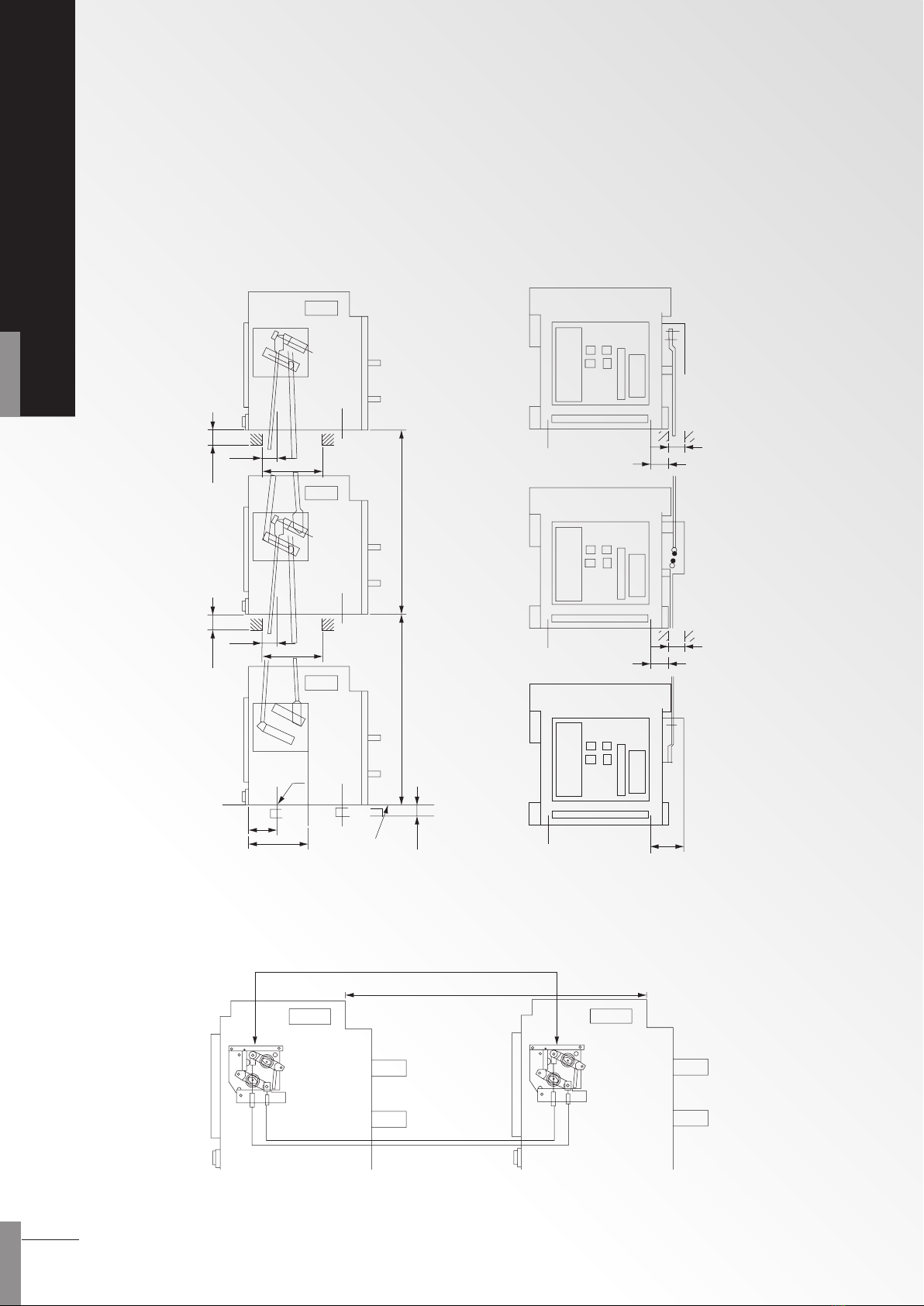
5.3 Lock devices (optional)
5.3.1 Mechanical interlock (ATS use)
The interlock device is installed on the right side of ACB. The maximum of 3 units of ACB can be installed vertically, and 2
units horizontally. It prevents the 2 or 3 ACBs close at the same time.
breaker 2
breaker
Stacked circuit breaker interlocking devices (If there are two circuit breaker interlocks, remove one of them.)
3
breaker 1
50
600600
45
40
180
50
40
65
166
180
60
52
100
60
52
basic point
circuit breaker
cradle
Standard 1.5m, MAX. 2M.
Interlocking device of the flat-fixed breakers
ACB-OB
16
AIR CIRCUIT BREAKER
D
1
D2D3
D
1
D
2
D
1
D
2
0 0
0 1
1 0
D
1
D
2
0 0
1 0
0 0
D
3
0
0
1
1 1
0 1
0
0
D
1
D
2
0 0
1 0
D
3
0
0
0 1
0 0
0
1
D
1
D
2
0 0
1 0
0 1
D
3
0
0
0
0 0
1 1
1
0
0 1
1 0
1
1
D
1
D2D3
D2D3
D
1
wiring possible cause wiring possible cause
3×breaker lock
2×normal power + 1×back up power
2×breaker lock
wiring possible cause
3×breaker lock
3×normal power for one breaker
wiring possible cause
3×breaker lock
double power and one switch
ACB mechanical interlock action gure
(Fig. 1)
(Fig. 2)
(Fig. 3)
(Fig. 4)
(Fig. 5)
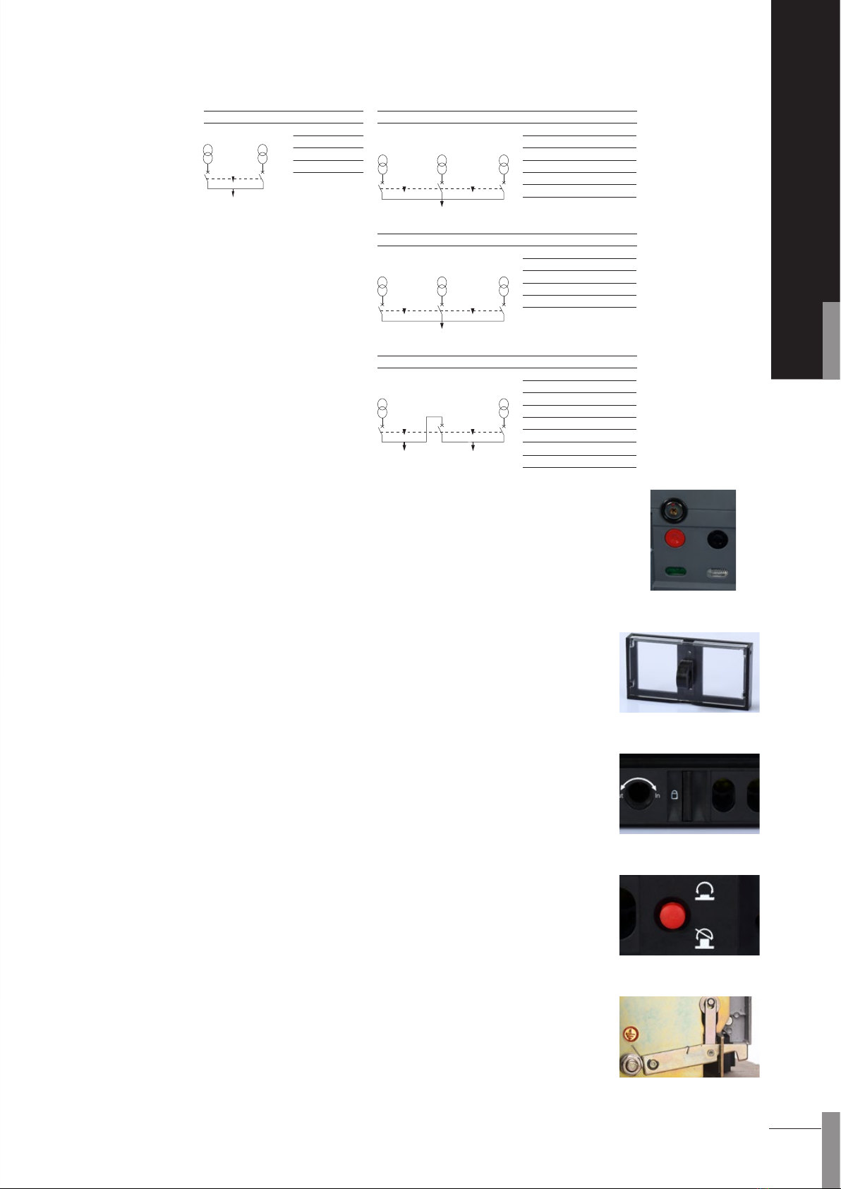
5.3.2 Three-lock-two-key interlocking device
The three-lock-two-key interlocking devices are used on occasions where the breakers are
xed dispersedly. The locks are xed on the panels of the three breakers separately. When the
key had been inserted and rotated to horizontal position, the breaker can carry on make-break
operation. The closed breaker will be broken if rotate the key anticlockwise from horizontal to
vertical position. At the same time, making operation is forbidden and the key is allowed to
take out. It ensures that there are not more than two breakers can be closed at the same time
because there are only two keys for three locks.
5.3.2.1 Key lock
The structure of the breaking lock is the same as the three-lock-two-key. However, there is only
one key for one lock. If the o button of the breaker is locked, the on button will be disabled.
5.3.4 Button lock
The cover on the ON/OFF button with padlock position attached on ACB panel. This device
doesn't come with padlock.
5.3.5 Racking lock
It is used in drawout type breaker and it is possible to lock the disconnection, connection, test
positions.
5.3.6 Position lock
The red color button will pop up and lock the breaker main body in the position of
disconnected, test or connected.
Press the red button for continuing draw in/out the main body.
The padlock can be attached on this device.
5.3.3 Door interlock
This prevents the compartment door to be opened when the circuit breaker closed. The cdoor
interlock xed in the foot right corner of the drawer seat.
a. The door interlock is allowed to close or open at will if the breaker is at the disconnection
position (relative to cradle).
b Breaker can be pushed in or pulled out to any position between connection and
disconnection if the compartment
door opens.
c. Breaker will be locked once the door is closed after the breaker leaving the disconnection
position.
(Fig. 1)
(Fig. 1)
(Fig. 2)
(Fig. 3) (Standard)
(Fig. 4)
(Fig. 5)

ACB-OB
17
INSTRUCTIONS
Leading wire functions:
#1 and #2 : It is the working power supply input; For DC working power, #1 is the positive end.
#3 , #4 and #5 : It is the output of fault tripping contact ( #4 is the shared end); Contact capacity: AC380V, 16A
#6 , #7 and #8, #9 : It is the status auxiliary contact of two circuit breaker sets; Contact capacity: AC380V, 16A.
#10 and #11 : It is terminal A and B of RS485 communication outlet leading-out-wire (Only for XISC-P).
#12 and #13 : It is the output terminal of signal contact of the rst group of the controller (Only for XISC-P).
#14 and #15 : It is the output terminal of signal contact of the second group of the controller (Only for XISC-P).
#16 and #17 : It is the output terminal of signal contact of the third group of the controller (Only for XISC-P).
#18 and #19 : It is the output terminal of signal contact of the fourth group of the controller (Only for XISC-P).
#20 : It is for ground wire protection.
#21 , #22, #23 and #24 : It is the voltage display input terminal (Only for XSIC-P).
#25 and #26 : It is the input terminal of external transformer (leakage protection or for 3P+N).
6. Wiring
6.1 Controller and Circuit Breaker Wiring
External power
RS485 communication port
Voltage display
input wire
External
transformer
BW
5.4 Testing Kit
This testing device (ACB Tester) is an optional accessory, specic for ACB XSIC-II Intelligent
controller. ACB tester is mainly used to test ACB at site for routine check or repairing.
This manual suits for next models
3
Table of contents
Other Shihlin electric Circuit Breaker manuals

Popular Circuit Breaker manuals by other brands


Siemens
Siemens 3VL9600 - 4W 0 Series operating instructions

Westinghouse
Westinghouse Porcel-line DHP Series instructions

Moeller
Moeller LZMB Series installation instructions

Siemens
Siemens Sensitrip III Sentron Series installation instructions

Allen-Bradley
Allen-Bradley 140G-I manual

GEYA
GEYA GRD9L-R instruction manual