Fonrich FR-DCMG-MMPS User manual

User Manual
Version 1.1
DC System Monitor:FR-DCMG-MMPS
丰郅(上海)新能源科技有限公司
Fonrich (Shanghai) New Energy Technology Co., Ltd.
Add: 1st Floor, Building 5, No.999 Jiangyue Road, Minhang District,Shanghai
Web: www.fonrich.com
Tel: +86 21 61679671
Email: sales@fonrich.com

1
Table of Contents
Documentation statement....................................................................................................................................1
Product description...........................................................................................................................................2
The main function.......................................................................................................................................2
Optional module..........................................................................................................................................3
Terminal description ...................................................................................................................................4
(Optional) PLC expansion module terminal description..............................................................................5
Ground connection and RS485 communication shielded wire....................................................................6
Wiring diagram of monitoring module.............................................................................................................7
(Optional)PLC system network wiring diagram ..............................................................................................8
System diagram..........................................................................................................................................8
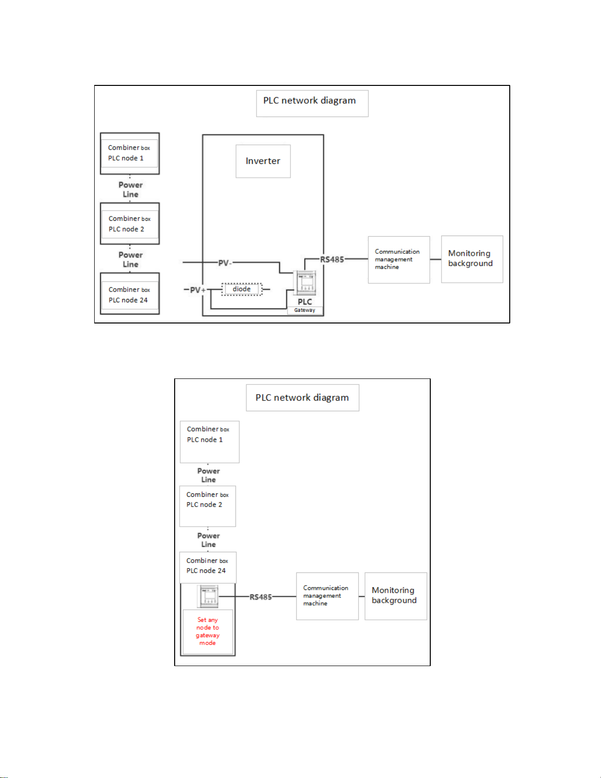
Network diagram.........................................................................................................................................9
Networking diagram of the gateway in the inverter.....................................................................................9
Networking diagram of the gateway in the junction box..............................................................................9
PLC wiring in combiner box and inverter..................................................................................................10
UI introduction .................................................................................................................................................11
Key operation ...........................................................................................................................................11
Boot interface ...........................................................................................................................................11
Current interface.......................................................................................................................................11
PLC status interface .................................................................................................................................12
Initial interface display ..............................................................................................................................12
Detailed data interface of channel current and power generation.............................................................12
Parameter settings....................................................................................................................................13
Trip self-test setting interface....................................................................................................................14
Current calibration setting interface..........................................................................................................15
System information display interface........................................................................................................15
Alarm status display interface...................................................................................................................16
DC arc fault alarm interface......................................................................................................................16
Fault alarm clear interface........................................................................................................................16
Alarm information management.....................................................................................................................17
Items that can generate alarms can be set...............................................................................................17
Items that can be tripped by setting..........................................................................................................17
Alarm conditions.......................................................................................................................................17
Alarm message.........................................................................................................................................18
Arc Alarm Strategy....................................................................................................................................18
MODBUS Protocol definition ..........................................................................................................................19

2
Communication format configuration ..............................................................................................19
Data frame format description (refer to Modbus RTU standard)......................................................19
Function code description...............................................................................................................19
Register description........................................................................................................................20
Register description in bit units (function code 02)..........................................................................20
Register description in word unit (function code 03 04 06)..............................................................30
PLC register: ....................................................................................................................................................37
Function code 03......................................................................................................................................37
Function code 06......................................................................................................................................42
The data of PLC node 1 is as follows, the data of other nodes are similar: .............................................43
Appendix ..........................................................................................................................................................45
FAQ..........................................................................................................................................................45
Document revision record.........................................................................................................................46
Contact us ................................................................................................................................................46

1
Documentation statement
This manual is applicable to the products with the models of FR-DCMG-MMPS. The software version
is the monitoring module of version A088 and above; this document also contains the description of
the optional product PLC.

2
Product description
FR-DCMG DC monitor products are mainly used in DC power transmission and distribution, such as
photovoltaic combiner boxes, DC cabinets, telecommunications equipment rooms and
communication base stations. It communicates with host computer through RS485 or power line
carrier(PLC). Its main function is to monitor the current of each branch in the DC system, the bus
voltage, the temperature of the cabinet, the status of the lightning arrester and the status of the DC
breaker. It can realize automatic alarm for abnormal conditions and real-time detection of the
presence of harmful arcs in the DC circuit. Once there is a harmful arc, it will immediately send an
alarm signal to directly drive the trip unit and cut off the faulty circuit, thereby effectively preventing
safety risks such as fire caused by arc.
The main function
•
Monitoring function: Real-time monitoring of the generation current, voltage, temperature of
the combiner box, lightning arrester status, DC circuit breaker status, and DC arc fault status
of each photovoltaic string in the combiner box, and communicate with the host computer
through RS485 or PLC.
•
Display content: For the detected voltage, current, temperature, switching state, power
generation and other data, the FR-DCMG-MMPS can display a histogram interface through
the LCD to read the current and other data more intuitively.
•
Alarm function: It can be configured to open or close the alarm and shunt release functions
according to the actual needs of the site (by default, only the arc alarm and trip functions are
enabled). When an alarm occurs, an alarm message will pop up on the interface.
•
Current calibration: identify zero drift and improve the accuracy of current identification.
(Default off)
•
Trip mode switching: The default o +, o- voltage is 0v, and the voltage output is 24v when
tripped. It can also be set to the opposite application.
•
Power line carrier communication module: through the power line carrier expansion module
DC-DCMG-PLCx, to achieve communication of up to 24 nodes
•
Compatibility:Program compatible model FR-DCMG-MMPD products

3
Optional module
Type
Model
Description
Optional: expansion
module
(PLC communication)
FR-DCMG-PLCD
power line carrier(PLC) expansion module for
1000V and below systems, needs to be used
with FR-DCMG-MMPL
FR-DCMG-PLCU
For 1500V and below systems
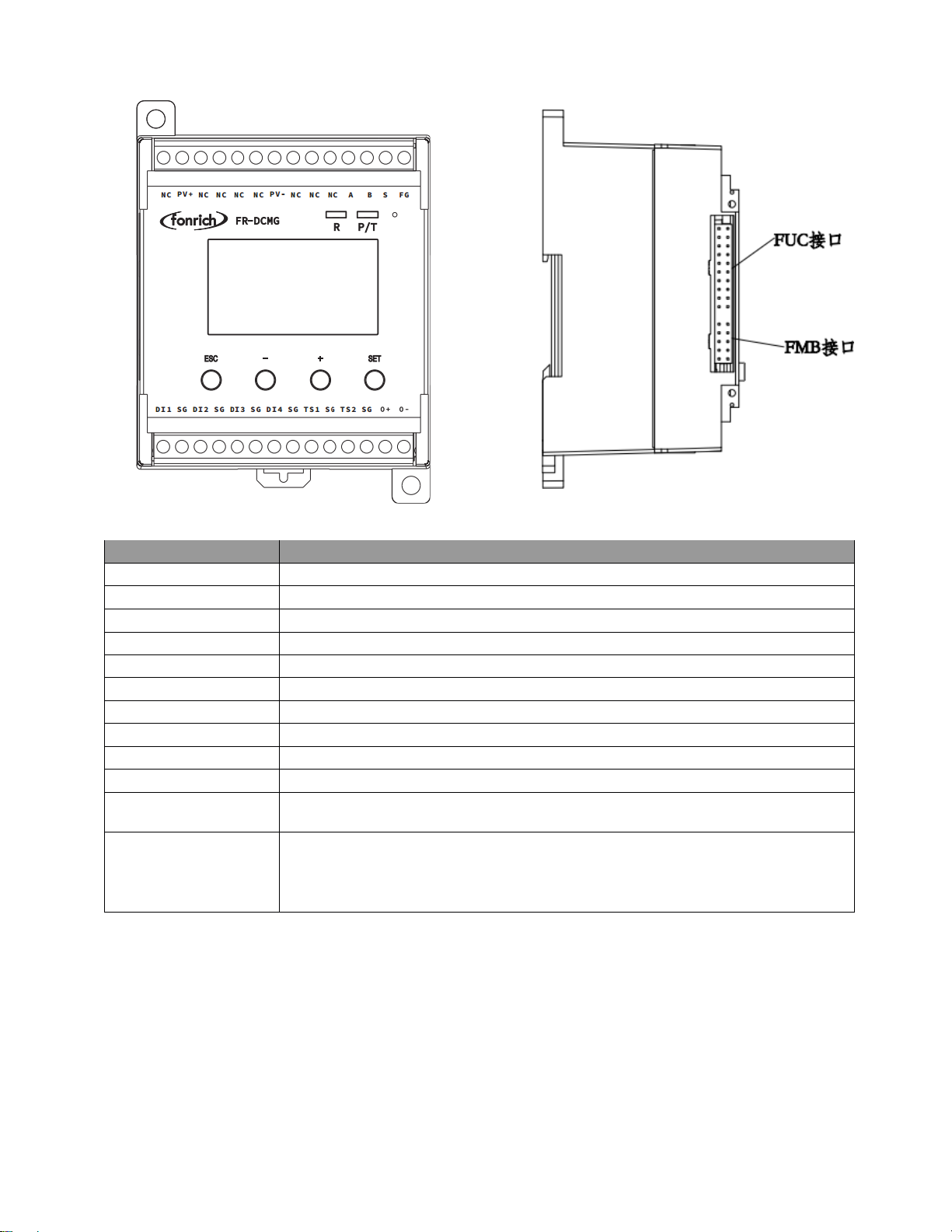
4
Terminal Definition
Symbol
Meaning
PV+ . PV-
PV DC bus power supply terminal
NC
Not connecion
S
Not connecion
A.B
RS485 Communication terminal
FG
Fixed Ground terminal
TS1.TS2
Externally connected temperature sensor terminals
SG
Temperature sensor and digital input ground terminal
DI1.DI2.DI3.DI4
4 digital input terminals
0+.0-
Connecting the shunt release
FUC
Can connect modules with FUC interface
FMB
Modules with an FMB interface can be connected, such as the FR-
DCMG-AS4A DC Arc Detector.
O+、SG
DC 24V power supply terminal, bidirectional power supply, external
output current maximum 100mA, but it is not recommended to use the
module for external power supply, which will affect the internal
temperature rise of the module
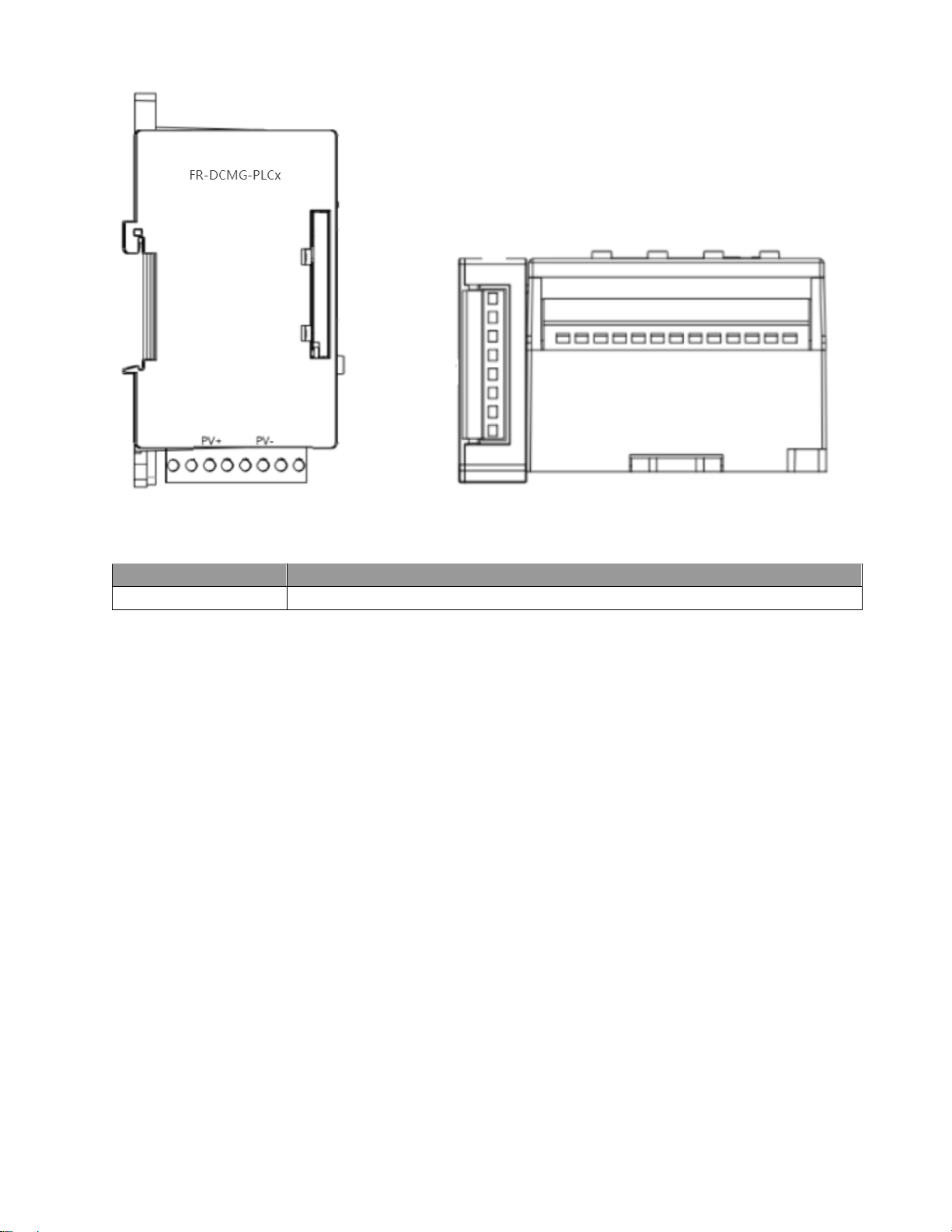
5
(Optional) PLC expansion module terminal description
Symbol
Meaning
PLCx PV+ . PV-
PLCx expansion module DC power terminal
6
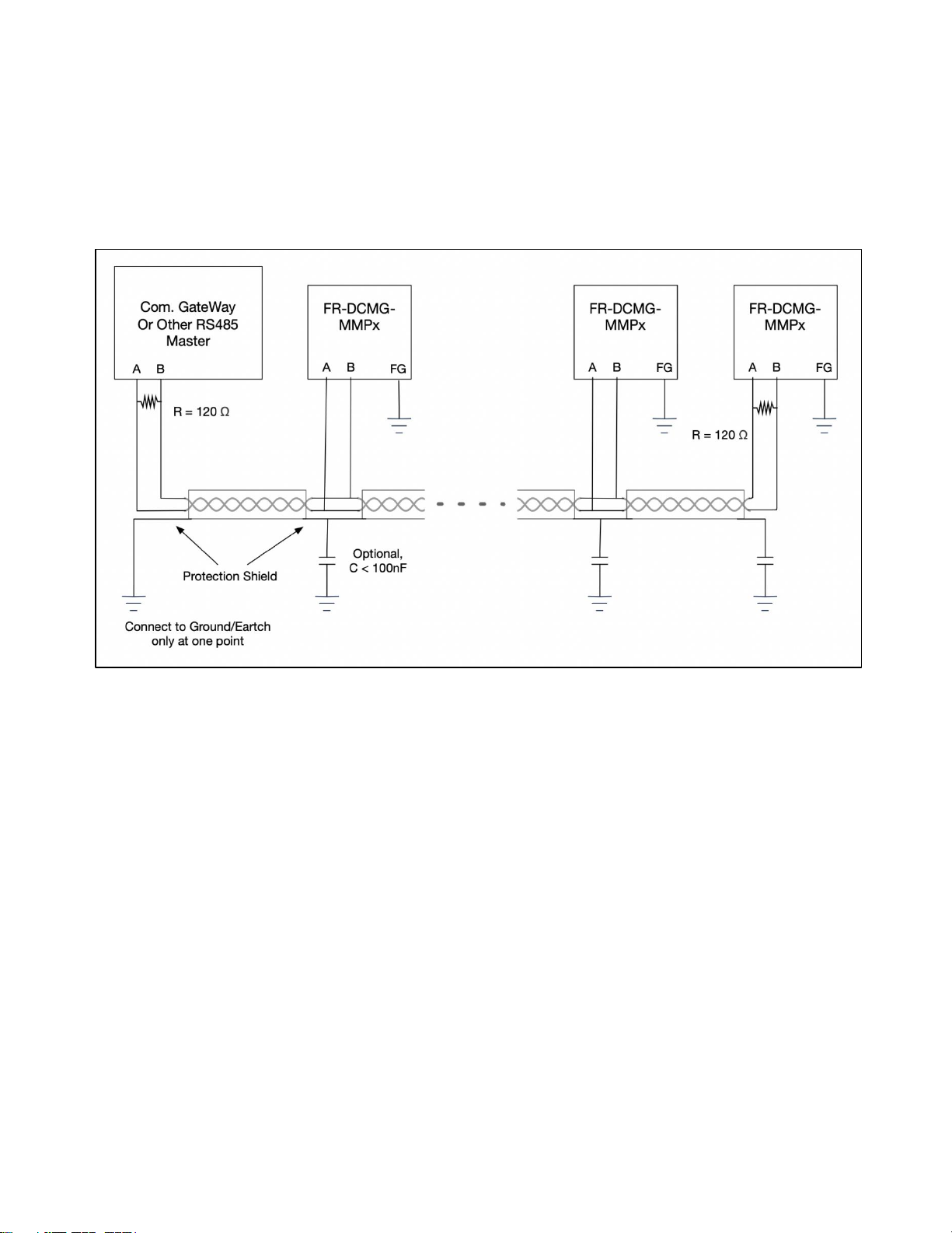
Ground connection and RS485 communication shielded wire
The FG terminal of the FR-DCMG must be grounded, otherwise communication will interfere and the
reliability of the device will decrease. The grounding wire should be grounded nearby. The grounding
wire should be no more than 15cm from the “FG” terminal to the bottom of the combiner box. It is
recommended to be within 10cm. The shorter the better, the thicker the better. The bottom of the
combiner box should be connected to the ground. The main control unit module is fixed on a
standard guide rail with a width of 3.5 cm.
The wiring specifications of the communication shielded wire are shown in the figure above:
The wiring of on-site communication lines requires that the communication shield can only be
grounded at a single point, otherwise there will be a risk of lightning surge damage to all equipment
on the entire communication line during a lightning strike;
If you encounter a situation where communication line interference is too large to communicate, you
can refer to the figure above, and insert a high voltage capacitor C <100nF between the shielded
wire of each combiner box and the ground wire, and use this capacitor to filter the shielding layer
interference.
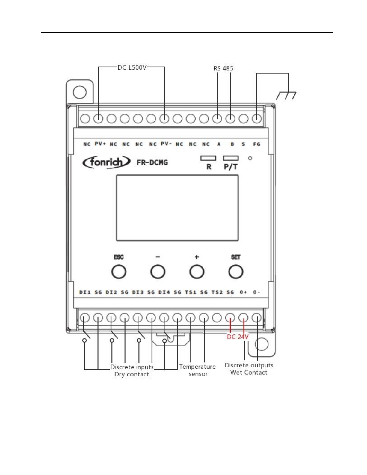
7
Wiring diagram of monitoring module

8
(Optional)PLC system network wiring diagram
System diagram
9
Network diagram
Networking diagram of the gateway in the inverter
Networking diagram of the gateway in the junction box
10
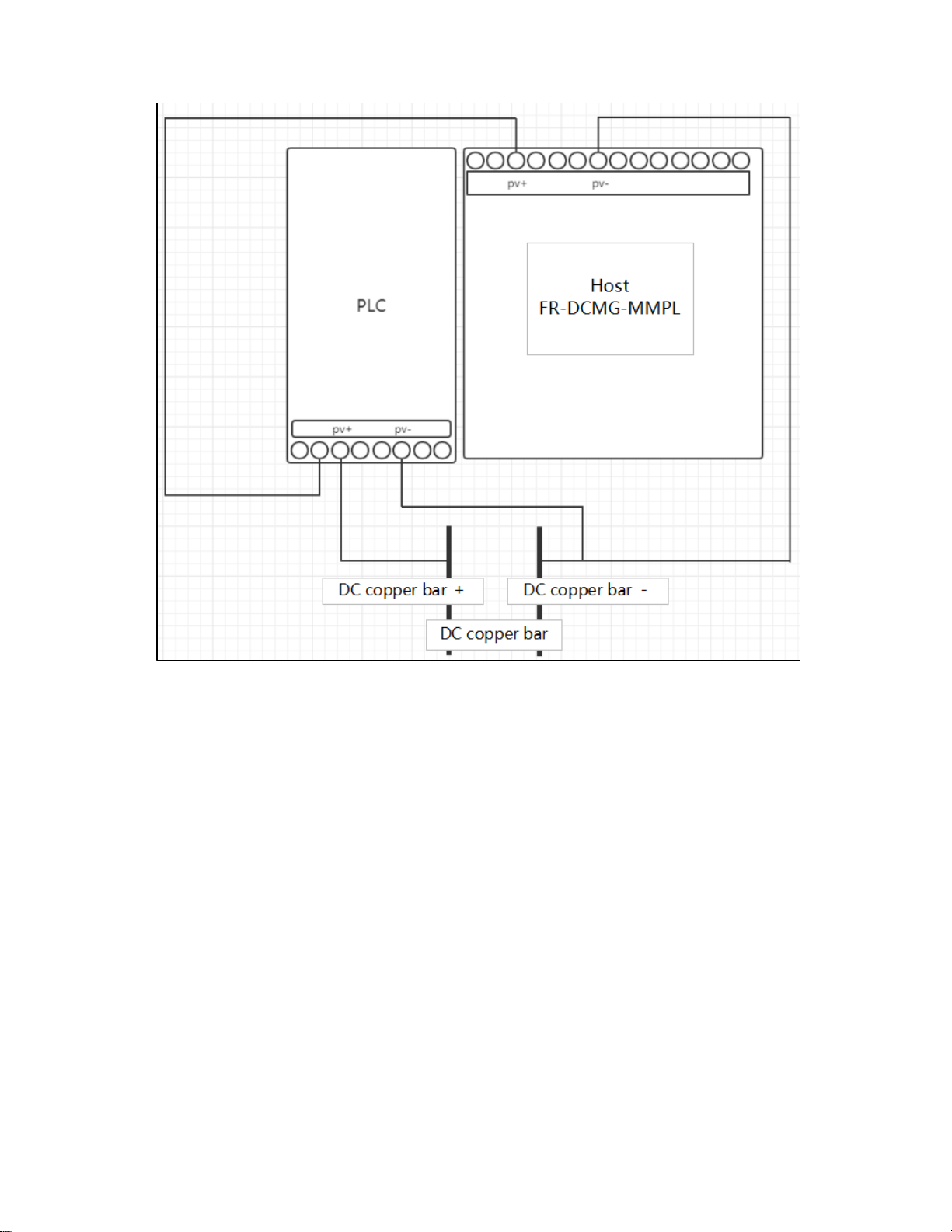
PLC wiring in combiner box and inverter

11
UI introduction
Key operation
FR-DCMG-MMPS has four keys “ESC”, “-”, “+”, and “SET”.
"ESC" key is used to return to the default interface and cancel parameter setting and View PLC
status;
“SET”key is used to enter the parameter setting mode, select the parameter to be set and complete
the setting of the parameter;
The "+" and "-" keys are used to scroll the screen and adjust parameters;
Press the "+" and "-" keys at the same time to display the software version interface;
Press the "ESC" and "-" keys simultaneously to display the current calibration interface;
Press the “ESC” and “+” keys simultaneously to display the trip self-test interface;
If there is no key operation for 10 seconds, the interface will automatically jump to the default
interface of the current mode, and the brightness will decrease after 5 seconds.
Boot interface
After the device is powered on, the following interface will be displayed:
Current interface
After the boot interface, the histogram interface will be displayed, as shown below:
①It indicates that the connected Hall has the arc detection function, and the ordinary Hall does not
have this mark;
②The number of online current channels varies according to the number of Halls actually connected;
③Switch input status: DI1, DI2, DI3, DI4 real-time status;
④Real-time temperature;
⑤Real-time voltage;

12
⑥Current histogram; the default display range is -2A ~ 10A, and the display range can be expanded
by setting register 0x0B16;
⑦Histogram partition: because 6 Halls are inserted, 6 partitions
PLC status interface
In the histogram interface, without the PLC expansion module connected, press the ESC key to
display the following interface:
With the PLC expansion module connected, press the ESC key to display the following interface:
Node mode Gate mode
•
SNR is the signal-to-noise ratio of the current PLC line
•
SEND xxx is the number of data packets that have been sent by the current node
•
The figure on the right shows the PLC status information of the node, the rows and columns
of the table, for example
•
The fifth in row 1 shows the node with address 5
•
The first display in row 2 is the node with address 9
•
The second in row 3 shows the node with address 18
•
PLC supports a maximum of 24 nodes, and the address range of these 24 nodes is 1 ~ 24.
•
The communication quality is represented by numbers 0-9 (for example: the data of the node
with address 5 in the above figure can be received, and the communication quality is the best
9)
Initial interface display
The factory default is Modbus mode. When the host computer is connected to the device via RS485
and communicates, the LED lights “R” and “P / T” will flash alternately to indicate normal
communication. When the device is not connected to communication, it restarts by default every 5
minutes, or you can turn off the default restart function, which can be turned off through the 0xF003
register.
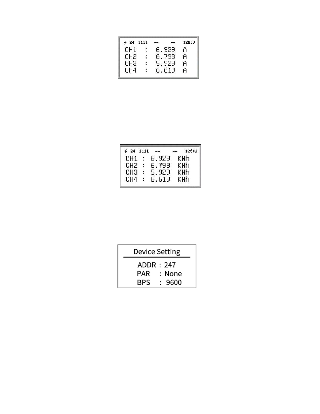
Detailed data interface of channel current and power generation
Under the current interface, press the "+" or "-" key to enter the channel current and power
generation display interface. The current value and cumulative power generation of each channel are
displayed on the screen. When the "+" key is pressed first, the digital value of the current is displayed
13
first, and when the "-" is pressed first, the digital value of the current is displayed first
The value of cumulative power generation. When viewing the values of current and cumulative power
generation, you can scroll through the screen by continuing to press the "+" or "-" key. After the
current display is completed, continue to press the "+" key to start displaying the cumulative power
generation. The figure above shows the current display interface. “CH1:” in the figure indicates that
the current value monitored by channel 1 in real time is “6.929A”, and so on.
The figure below shows the cumulative power generation display interface. "CH1:" in the figure
indicates that the cumulative power generation of channel 1 is "6.929kwh", and so on.
Parameter settings
Press the "SET" key to enter the Modbus parameter setting interface. The
Modbus parameter setting is as shown in the figure below:
•
ADDR: The communication address of the Modbus slave node, the range is 1 ~ 247 (default
is 247).
•
PAR: The data verification method of Modbus communication. The optional parity (None),
odd parity (Odd), even parity (Even), and no parity by default.
•
BPS: Baud rate for Modbus communication. The selectable baud rates are 2400, 4800, 9600
(default), 19200, 38400.
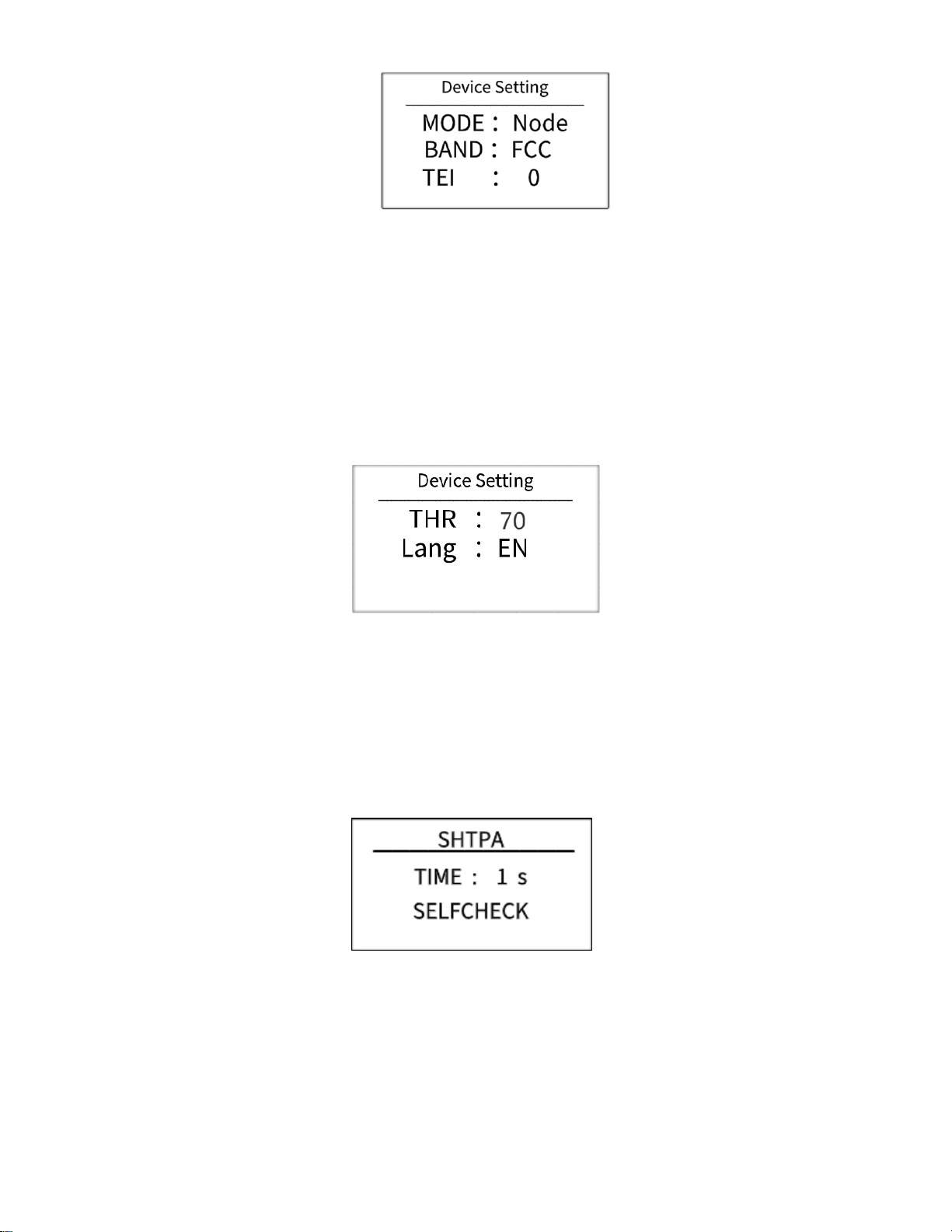
Press the "+" key to select down to the second page of the setting
interface
14
•
MODE: PLC mode (Gate gateway, Node node, node address and Modbus address are the
same, setting range 1-24)
•
BAND: PLC frequency band (currently only supports FCC, please consult technical staff for
other options)
•
TEI: PLC's network identification (the TEI under the same network must be consistent,
otherwise it cannot communicate, the setting range is 0-99)
Press the "+" key to continue the selection down to the third page of the
setting interface:
•
THR:Arc alarm threshold (default: 70)
•
LANG:language settings(default: EN)
Trip self-test setting interface
Press the “ESC” and “+” keys at the same time to enter the shunt trip setting interface.
(Factory default)Release mode (o ±DC voltage is 0v), the interface is as follows:
(Special needs)Relay mode (o ±DC voltage is 24v), the interface is as follows:

15
In the shunt trip setting interface, you can set the enable time (TIME) and trip self-check
(SELFCHECK) of the shunt trip during the arc alarm.
When "*" flashes in the TIME line, press the "SET" key and then press ±to modify the shunt release
time.
When "*" flashes on the SELFCHECK line, press the "SET" key, and the self-check of the shunt
release will be performed automatically.
The specific behavior is that when the time is reached, the shunt release operates, and after the
enabling time has passed, the shunt release is restored.
Current calibration setting interface
Press the "ESC" and "-" keys at the same time to enter the current calibration setting interface, as
shown below:
Note:To use this feature, please contact the company's technical support staff.
System information display interface
In the histogram interface, press the "+" and "-" keys at the same time to enter the software version
number display interface, as shown below:
•
HV:Keep
•
SV:Software version number
•
ST:Keep
16
Alarm status display interface
Alarm messages can be cleared remotely and manually. Manual clearing requires long-pressing the
host's "ESC" key for 2 seconds, remote clearing requires writing "1" to register 0x0079 to clear. If an
arc trip alarm occurs, it must be cleared manually or remotely. Restarting the host will still display the
alarm message.
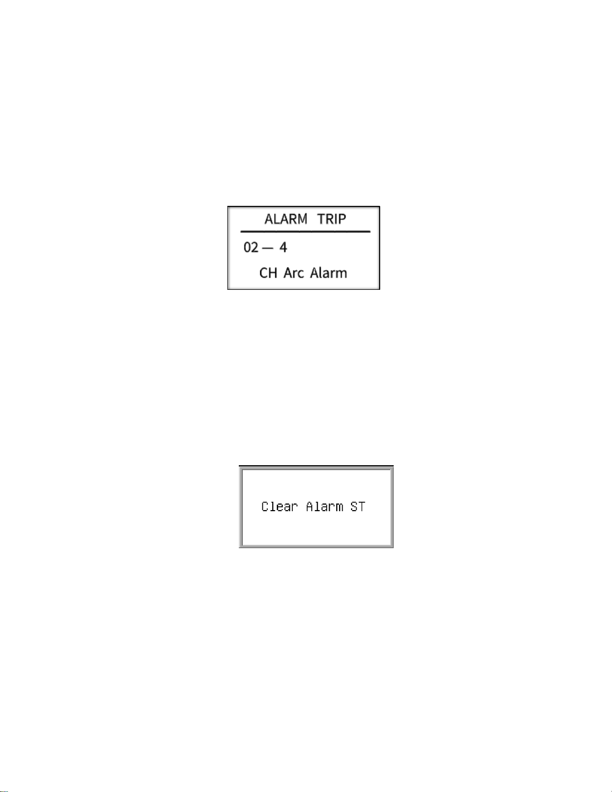
DC arc fault alarm interface
After the DC arc sensor detects the occurrence of a fault arc, the alarm information interface of the
host is as shown below.
In the figure above: "02" means channel arc fault alarm, and "4" means that the fault arc alarm
channel is 4.
Fault alarm clear interface
The host sends an alarm when it detects a fault, and the user can choose to handle it locally or
remotely. By long-pressing the "ESC" key for about 5 seconds locally, the system jumps out of the
interface as shown below, indicating that the alarm status has been cleared; remote processing
needs to write "1" to 0x0079 to clear, and the interface shown below will be displayed after clearing
successfully.

17
Alarm information management
Items that can generate alarms can be set
Channel arc
Voltage is too high
Voltage is too low
Temperature is too high
Channel reverse current
Total reverse current is too high
Total current is too high
Total current is too low
Channel without current
Low channel current
High channel current
Channel current value undercurrent
Channel current value overcurrent
Lightning Arrester Status (DI1)
circuit breaker status (DI2)
Switch DI3 status
Switch DI4 status
Items that can be tripped by setting
Channel arc
Voltage is too high
Temperature is too high
Channel reverse current
Total reverse current is too high
Total current is too high
Channel without current
Low channel current
High channel current
Channel current value undercurrent
Channel current value overcurrent
Lightning Arrester Status (DI1)
Circuit breaker status (DI2)
Monitor DI3 status
Monitor DI4 status
Alarm conditions
1.
Current reverse, no current, under current, over current, low current, high current, etc.
a. Only when the average value of the channel current is greater than the set
alarm threshold of the current channel, the alarm function of the above current-
related items is activated; otherwise, the alarm status is forcibly cleared to 0.
b. As for whether the alarm needs to be separately met the respective alarm conditions
(above or below the respective alarm threshold).Alarm message
c. Check if the corresponding alarm register is open, closed by default
Other manuals for FR-DCMG-MMPS
1
Table of contents
Other Fonrich Monitor manuals


