Fonrich FR-DCMG-MMPS User manual

User Manual
Version 1.5
DC System Monitor:FR-DCMG-MMPS
Scan the code to learn more
Fonrich (Shanghai) New Energy Technology Co., Ltd.
Add: 1st Floor, Building 5, No.999 Jiangyue Road, Minhang District,Shanghai
Web: www.fonrich.com
Tel: +86 21 61679671
Email: sales@fonrich.com

1
Table of Contents
Table of Contents............................................................................................................................................................1
1 Documentation statement...............................................................................................................................................3
2 Safety Precautions...........................................................................................................................................................3
2.1 Signs.........................................................................................................................................................................3
2.2 Safety Precautions....................................................................................................................................................3
2.3 Personnel requirements............................................................................................................................................ 3
2.4 Electrical connection................................................................................................................................................4
2.5 System running........................................................................................................................................................ 4
3 Product description.........................................................................................................................................................5
3.1 The main function.................................................................................................................................................... 5
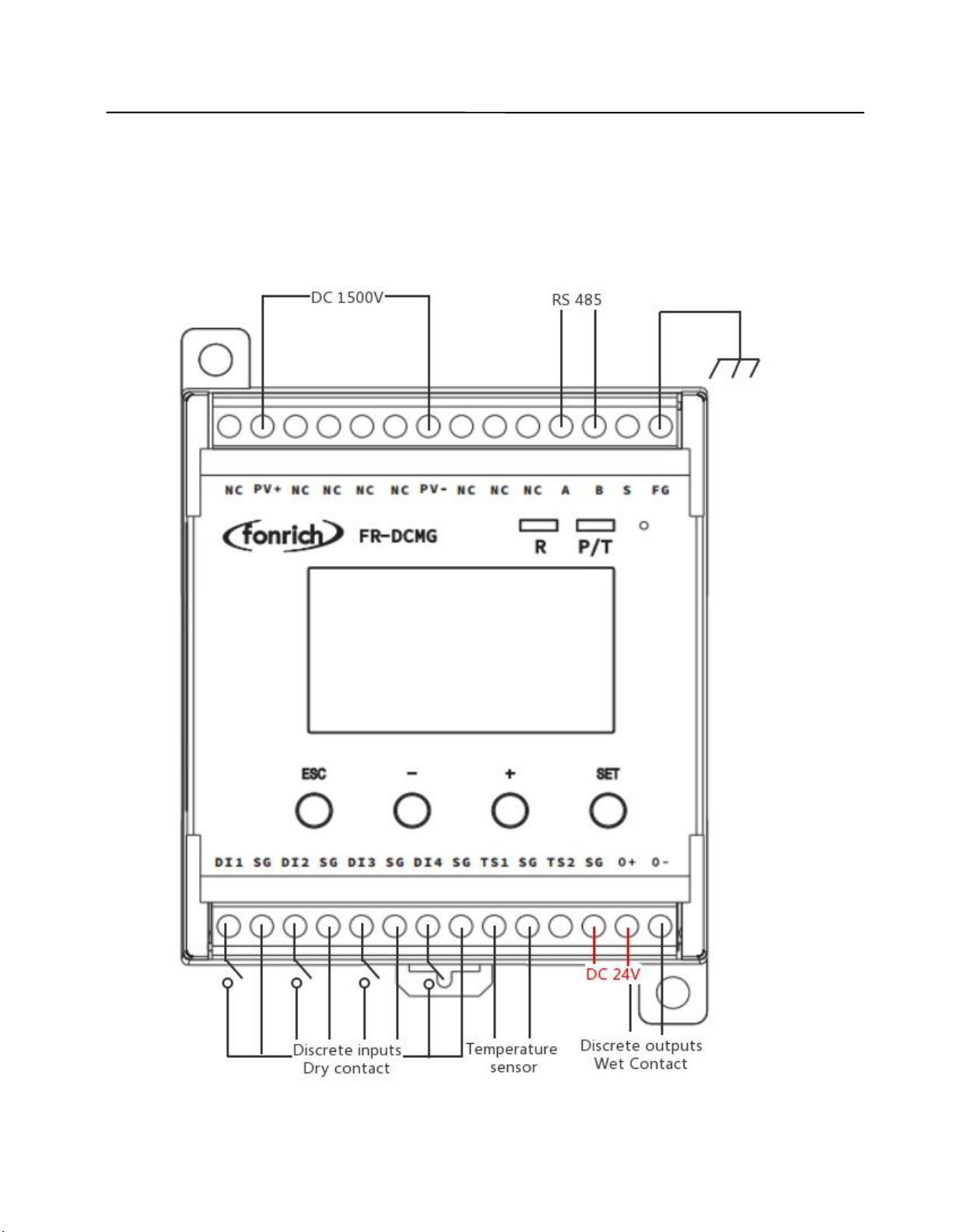
3.2 Terminal Definition.................................................................................................................................................6
4 Wiring diagram of monitoring module.........................................................................................................................7
4.1 Electrical wiring diagram.........................................................................................................................................7
4.2 Ground connection and RS485 communication shielded wire................................................................................ 8
5 UI introduction................................................................................................................................................................9
5.1 Key operation...........................................................................................................................................................9
5.2 Boot interface...........................................................................................................................................................9
5.3 Current interface...................................................................................................................................................... 9
5.4 Channel current data.............................................................................................................................................. 10
5.5 Parameter settings..................................................................................................................................................10
5.6 Trip self-test setting interface................................................................................................................................ 11
5.7 Current calibration setting interface...................................................................................................................... 12
5.8 System information display interface.................................................................................................................... 12
5.9 Alarm status display interface............................................................................................................................... 13
5.10 DC arc fault alarm interface................................................................................................................................ 13
5.11 Fault alarm clear interface................................................................................................................................... 13
6 Alarm information management.................................................................................................................................14
6.1 Items that can generate alarms can be set..............................................................................................................14
6.2 Items that can be tripped by setting....................................................................................................................... 14
6.3 Alarm conditions................................................................................................................................................... 15
6.3.1 Alarm judgment condition........................................................................................................................15
6.3.2 Trip judgment condition...........................................................................................................................15
6.4 Alarm message.......................................................................................................................................................15
6.5 Arc Alarm Strategy................................................................................................................................................15
6.5.1 Arc mode.................................................................................................................................................. 15
6.5.2 Arc alarm strategy.................................................................................................................................... 16

2
6.5.3 Arc alarm time..........................................................................................................................................16
6.6 Combined alarm strategy (closed by default, follow the steps below when needed)............................................16
7 MODBUS Protocol Definition..................................................................................................................................... 17
7.1 Communication format configuration................................................................................................................... 17
7.2 Data frame format description (refer to Modbus RTU standard).......................................................................... 17
7.2.1 Data message example............................................................................................................................. 17
7.3 Function code description......................................................................................................................................18
Register reads and writes in bits........................................................................................................................18
Register read and write in word units................................................................................................................18
7.4 Register description............................................................................................................................................... 18
7.4.1 Register description in bit units (function code 02)................................................................................. 18
7.4.2 Register description in word unit (function code 03 04 06).....................................................................30
8 Appendix....................................................................................................................................................................... 38
8.1 Document revision record......................................................................................................................................38
8.2 Contact us.............................................................................................................................................................. 39

3
CAUTION
1 Documentation statement
This manual applies to the product model FR-DCMG-MMPS, and the software version is A08D.
2 Safety Precautions
2.1 Signs
The following signs may appear in this article, and their meanings are as follows.
2.2 Safety Precautions
Please read the safety precautions in this user manual carefully to avoid personal injury and
property damage.
2.3 Personnel requirements
The installation and operation of FR-DCMG-MMPx must be carried out by a professional
electrician.
The operator should be fully familiar with the composition and working principle of the entire
photovoltaic grid-connected power generation system, as well as the relevant standards of the
country/region where the project is located.
Live operation is strictly prohibited during installation. Before installation, make sure that both
the DC side and the AC side are powered off.
Signs
Instructions
Indicates a hazardous situation which,if not avoided, will result in
death or serious injury.
Indicates a hazardous situation which,if not avoided, could result in
death or serious injury.
Indicates a hazardous situation which,if not avoided, could result in
minor or moderate injury.
Indicates a situation which,if not avoided, can result in property
damage.
It is not safety warning information, and does not involve personal,
equipment and environmental damage.
Note
Protrudes important or critical information, best practices, tips, etc.
It is not safety warning information, and does not involve personal,
equipment and environmental damage.
WARNING
DANGER
NOTICE

4
Please read this user manual carefully before installation. If the equipment is damaged due to
failure to install in accordance with this user manual, our company reserves the right not to guarantee
the quality.
Before installation, make sure that it is not electrically connected and powered on.
During the installation process, except for the wiring terminals of the arc box, please do not touch
other parts inside.
Before making electrical connections, make sure that the voltage of the positive and negative
poles of the DC busbar of the combiner box is 0V.
2.4 Electrical connection
Before electrical connection, please make sure that FR-DCMG-MMPx is not damaged and in a safe
state, otherwise it may cause electric shock.
All electrical connections must meet the electrical standards of the country/region where they are
located.
The cables used in the PV combiner box must be firmly connected, well insulated, and have
appropriate specifications.
2.5 System running
FR-DCMG-MMPx has high voltage during operation, which may cause electric shock or death
in severe cases. Please operate strictly in accordance with the safety precautions listed in this manual
and other related documents.

5
3 Product description
FR-DCMG DC monitor products are mainly used in DC transmission, power distribution and
other occasions, such as photovoltaic combiner boxes, arc protection boxes, etc. Through RS485
communication with the host computer, its main functions include real-time monitoring of the current
of each branch in the DC system, the temperature of the cabinet, the status of the lightning arrester
and the status of the DC circuit breaker, etc. It can realize automatic alarm for abnormal conditions
and real-time detection of harmful arcs in the DC circuit. Once there are harmful arcs, an alarm signal
will be sent immediately to directly drive the trip unit and cut off the fault circuit, thereby effectively
preventing potential safety hazards such as fires caused by arcs.
3.1 The main function
Monitoring function: real-time monitoring of the generation current, voltage, temperature of the
combiner box, lightning protector status, DC circuit breaker status, and DC arc fault status of
each photovoltaic string in the combiner box, and communicate with the host computer through
RS485.
Display content: For the detected current, temperature, switch status and other data, FR-DCMG-
MMPS can display histogram interface through LCD, and read current and other data more
intuitively.
Alarm function: According to the actual needs of the site, it can be configured to turn on or off
the alarm and shunt release functions (by default, only the arc alarm and trip functions are turned
on). When alarming, the interface pops up alarm information.
Tripping mode switching: The default O+, O- voltage is 0V, and the voltage output is 24V
when tripping, or it can be set to the opposite application.

6
3.2 Terminal Definition
Symbol
Meaning
PV+/PV-
Measuring voltage
NC
Not connecion
S
Not connecion
A/B
RS485 Communication terminal
FG
Fixed Ground terminal
TS1/TS2
Externally connected temperature sensor terminals
SG
Temperature sensor and digital input ground terminal
DI1/DI2/DI3/DI4
4 digital input terminals
O+/O-
Connecting the shunt release
FUC
Can connect modules with FUC interface
FMB
Modules with an FMB interface can be connected, such as the FR-
DCMG-AS4A DC Arc Detector.
O+/SG
24V power supply terminal, O+ connects to 24V+, SG connects to 24V-
7
4 Wiring diagram of monitoring module
4.1 Electrical wiring diagram
Note: O+ is connected to 24V+, SG is connected to 24V-, if the connection is reversed, the module
may be damaged

8
4.2 Ground connection and RS485 communication shielded wire
The FG terminal of the FR-DCMG must be grounded, otherwise communication will interfere
and the reliability of the device will decrease. The grounding wire should be grounded nearby. The
grounding wire should be no more than 15cm from the “FG” terminal to the bottom of the combiner
box. It is recommended to be within 10cm. The shorter the better, the thicker the better. The bottom of
the combiner box should be connected to the ground. The main control unit module is fixed on a
standard guide rail with a width of 3.5 cm.
The wiring specification of the communication shielded wire is shown in the figure below:
The wiring of on-site communication lines requires that the communication shield can only be
grounded at a single point, otherwise there will be a risk of lightning surge damage to all equipment
on the entire communication line during a lightning strike;
If you encounter a situation where communication line interference is too large to communicate,
you can refer to the figure above, and insert a high voltage capacitor C <100nF between the shielded
wire of each combiner box and the ground wire, and use this capacitor to filter the shielding layer
interference.
9
5 UI introduction
5.1 Key operation
FR-DCMG-MMPS has four keys "ESC", "-", "+", and "SET".
"ESC" key is used to return to the default interface and cancel parameter settings;
"SET" key is used to enter the parameter setting mode, select the parameter to be set and complete
the setting of the parameter;
The"+"and "-" keys are used to scroll the screen and adjust parameters;
Press the"+"and "-" keys at the same time to display the software version interface;
Press the "ESC" and "-" keys simultaneously to display the current calibration interface;
Press the "ESC" and "+" keys simultaneously to display the trip self-test interface;
If there is no key operation for 10 seconds, the interface will automatically jump to the default
interface of the current mode, and the brightness will decrease after 5 seconds.
5.2 Boot interface
After the device is powered on, the following interface will be displayed:
5.3 Current interface
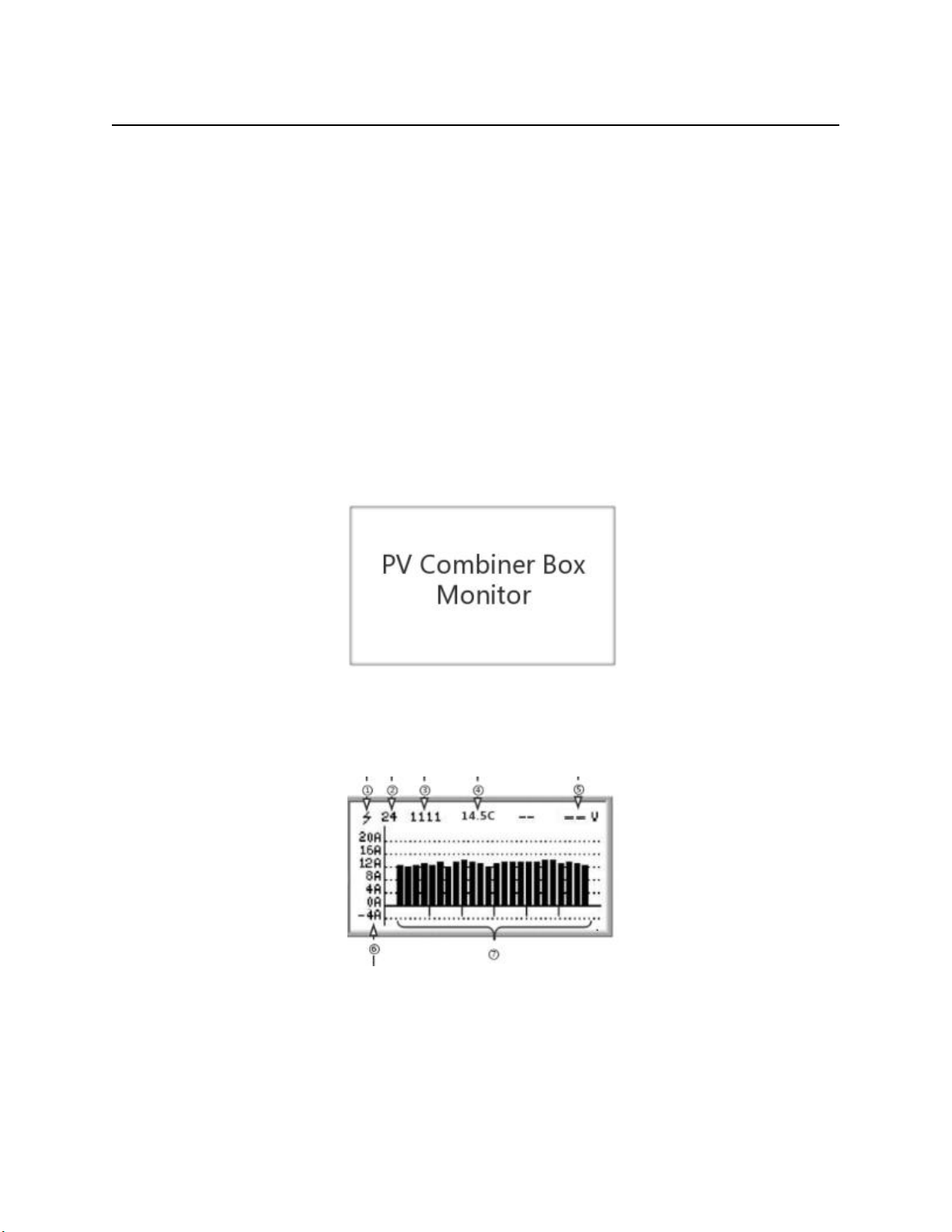
After the boot interface, the histogram interface will be displayed, as shown below:
①It indicates that the connected Hall has the arc detection function, and the ordinary Hall does not
have this mark;
②The number of online current channels varies according to the number of Halls actually
connected;
③Switch input status: DI1, DI2, DI3, DI4 real-time status;
④Real-time temperature;
⑤No voltage displayed when PV+/PV- is not connected;
10
⑥Current histogram; the default display range is -4A ~ 20A, and the display range can be
expanded by setting register 0x0B16;
⑦Histogram partition: because 6 Halls are inserted, 6 partitions
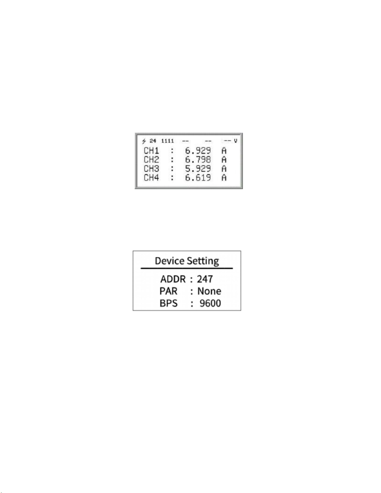
5.4 Channel current data
In the current interface, press the "+" or "-" key to enter the channel current display interface,
and the current value of each channel is displayed on the screen. You can scroll through the screen by
continuing to press the "+" or "-" key. The picture above is the current display interface. "CH1:" in the
above figure indicates that the real-time monitoring current value of channel 1 is "6.929A", and so on.
5.5 Parameter settings
5.5.1 Press the "SET" key to enter the Modbus parameter setting interface. The Modbus
parameter setting is as shown in the figure below:
ADDR: The communication address of the Modbus slave node, the range is 1 ~ 247 (default is
247).
PAR: The data verification method of Modbus communication. The optional parity (None), odd
parity (Odd), even parity (Even), and no parity by default.
BPS: Baud rate for Modbus communication. The selectable baud rates are 2400, 4800, 9600
(default), 19200, 38400.
5.5.2 Press the "+" key to select down to the second page of the setting interface
Note:For details, please refer to the FR-DCMG-MMPL manual,Press "+" key to go to the next
page.

11
5.5.3 Press the "+" key to continue to select downwards to the arc parameter setting interface:
MOD: Arc protection mode (Cont: continuous Arc Alarm mode, Single: Instantaneous Arc alarm
mode)
THR: Arc threshold (default 50)
IAT: 2 (Instantaneous Arc Time, default 2)
5.5.4 Press the "+" key to continue to select downwards to the arc parameter setting interface:
CAT: Continuous Arc Time (default 15)
LANG: Language setting (default: EN)
5.6 Trip self-test setting interface
Press "ESC" and "+" at the same time to enter the shunt tripping setting interface.
Release mode (O+/O- DC voltage is 0v), the interface is as follows:

12
(Factory default)Relay mode (O+/O- DC voltage is 24v), the interface is as follows:
On the shunt trip setting interface, you can set the shunt trip enable time (TIME) and trip self-check
(SELFCHECK) when an arc alarm occurs.
When the "*" flashes in the TIME line, press the "SET" key, and then press"+"or"-" to modify the
shunt release time.
When "*" flashes in the SELFCHECK line, press the "SET" key to automatically perform the self-
check of the shunt release.
The specific performance is: when the time is reached, the shunt release will act, and after the
enabling time, the shunt release will recover.
5.7 Current calibration setting interface
Press the "ESC" and "-" keys at the same time to enter the current calibration setting interface, as
shown below:
Note:To use this feature, please contact the company's technical support staff.
5.8 System information display interface
In the histogram interface, press the "+" and "-" keys at the same time to enter the software version
number display interface, as shown below:
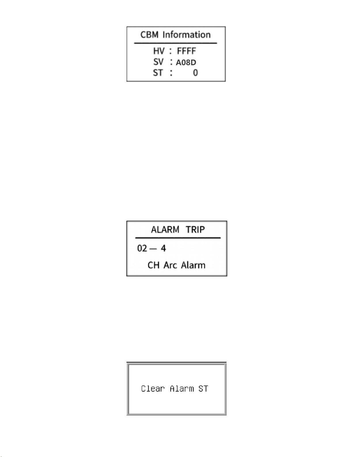
13
HV:—
SV:Software version number
ST:—
5.9 Alarm status display interface
Alarm messages can be cleared remotely and manually. Manual clearing requires long-pressing the
host's "ESC" key for 2 seconds, remote clearing requires writing "1" to register 0x0079 to clear. If an
arc trip alarm occurs, it must be cleared manually or remotely. Restarting the host will still display the
alarm message.
5.10 DC arc fault alarm interface
After the DC arc sensor detects the occurrence of a fault arc, the alarm information interface of the
host is as shown below.
In the figure above: "02" means channel arc fault alarm, and "4" means that the fault arc alarm
channel is 4.
5.11 Fault alarm clear interface
The host sends an alarm when it detects a fault, and the user can choose to handle it locally or
remotely. By long-pressing the "ESC" key for about 5 seconds locally, the system jumps out of the
interface as shown below, indicating that the alarm status has been cleared; remote processing needs
to write "1" to 0x0079 to clear, and the interface shown below will be displayed after clearing
successfully.

14
6 Alarm information management
6.1 Items that can generate alarms can be set
Channel arc
Voltage is too high
Voltage is too low
Temperature is too high
Channel reverse current
Total reverse current is too high
Total current is too high
Total current is too low
Channel without current
Low channel current
High channel current
Channel current value undercurrent
Channel current value overcurrent
Switch DI1 status
Switch DI2 status
Switch DI3 status
Switch DI4 status
6.2 Items that can be tripped by setting
Channel arc
Voltage is too high
Temperature is too high
Channel reverse current
Total reverse current is too high
Total current is too high
Channel without current
Low channel current
High channel current
Channel current value undercurrent
Channel current value overcurrent
Switch DI1 status
Switch DI2 status
Switch DI3 status
Switch DI4 status

15
6.3 Alarm conditions
6.3.1 Alarm judgment condition
Prerequisites for alarm judgment of channels such as reverse current, no current, undercurrent,
overcurrent, low current, and high current:
a. When the average value of the channel current is greater than the set current channel alarm
activation threshold, the alarm function of the above current-related items will be activated,
otherwise the alarm status will be forced to clear to 0;
b. As for whether the alarm needs to meet the respective alarm conditions (above or lower than
the respective alarm threshold).
c. Confirm whether the corresponding alarm register is turned on. By default, only the channel
arc alarm is turned on;Current reverse, no current, under current, over current, low current, high
current, etc. Channel alarm and trip judgment preconditions:
6.3.2 Trip judgment condition
Reverse current, no current, under current, over current, low current, high current channel alarm
and trip judgment prerequisites:
a. They need to meet their alarm conditions.
b. At the same time, when the cumulative number of alarm channels is greater than the set
number of trip channels, a trip will occur.
c. Confirm whether the corresponding trip register is open, the default is closed
6.4 Alarm message
•
Undercurrent alarm. After the channel average current value is subtracted from the overcurrent /
undercurrent alarm threshold, the current value is still less than or equal to the current channel start
alarm start threshold. The overcurrent / undercurrent alarm threshold will change as the average
current changes.
•
Over current alarm. After the channel average current value plus the over current / under current
alarm threshold, the current value is still greater than or equal to the current channel start alarm start
threshold. The over current / under current alarm threshold will change as the average current
changes.
•
Low current alarm, when the current is less than or equal to the channel current low alarm threshold, an
alarm occurs.
•
High current alarm. When the current is greater than or equal to the channel current high alarm
threshold, an alarm occurs.
•
No current alarm, when the absolute value of the current is less than 250mA, an alarm occurs.
6.5 Arc Alarm Strategy
6.5.1 Arc mode
We divide the arcs into Instantaneous Arc and Continuous Arc.
Instantaneous Arc
The arc duration does not exceed the Instantaneous Arc Time (IAT), and there is no arc occurring
again within the Continuous Arc Time (CAT).

16
Continuous Arc
The arc duration exceeds the IAT, or the arc duration does not exceed the IAT, but the arc occurs
again within the CAT.
6.5.2 Arc alarm strategy
1. Instantaneous arc alarm
If the arc intensity of any channel exceeds the channel alarm threshold, an arc alarm will be
generated.
2. Continuous arc alarm
The product does not alarm when instantaneous arc is detected, but only when continuous arc is
detected.
6.5.3 Arc alarm time
The calculation method of the arc alarm times of the channel: When an arc alarm occurs in any
channel, the number of arc alarm times increases by 1. When arc faults occur in several channels at
the same time, the number of arc alarm times only increases by 1. The product will automatically
restart after 2 minutes.
However, when the arc alarm times is up to the value of the arc alarm time, the device must be
restarted manually.
6.6 Combined alarm strategy (closed by default, follow the steps below when
needed)
The alarm will only take effect when two or more alarm conditions are met at the same time
Example: Simultaneously meet-when the voltage is lower than 800V and the total current is greater
than 50A, the module will alarm and trip.
operate:
Step 1: Turn on bit4 of 0x0B21 (2849) and 0x0B24 (2852);
Step 2: Turn on the low voltage (Bit2) and total current too high (Bit9) functions of 0x0B26 (2854);
Step 3: Turn on the alarms of 0x0B20 (2848) and 0x0B23 (2851) corresponding to low voltage
(Bit2) and high total current (Bit9);
Step 4 (optional): Set 0x0B05 (2821) total current too low,
The total current of 0x0B06 (2822) is too high,
The 0x0B01 (2817) voltage is too low, and the threshold of these 3 data is adjusted to a value that
meets the test conditions
illustrate:
• The status of the combined alarm is kept consistent with the register locations of other alarms
• The status of the combined alarm 03 The position of the function code is in bit 4 of the register
0x12B and 0x12E
• The status of the combined alarm 02 The position of the function code is 0x214 in the register
17
7 MODBUS Protocol Definition
7.1 Communication format configuration
•
Modbus communication mode: RTU mode
•
Address of the slave device: range form 1 to 247 (default 247)
•
Baud rate (bps): 2400, 4800, 9600 (default), 19200, 38400
•
Byte check mode: odd check, even check, no check (default)
7.2 Data frame format description (refer to Modbus RTU standard)
The byte in the communication frame composed by 1 start bit, 8 bits data bit, 1 parity bit, 1
stop bit like the below table(Refer to standard modbus RTU protocol):
Table 1: Data frame format table
Address Code
Function Code
Data Area
Check Zone
1byte
1byte
N*1byte
2bytes
The address code is used to identify the slave that receives the data frame and the response
frame sent by that slave. The function code indicates how the master requires the slave to respond
and the slave responds to that function code. Data area The content can be the address value, the
number of registers, the data from the slave response and the data sent by the master to the slave,
etc., which can hold up to 252 bytes of data. The check area uses CRC cyclic redundancy to check
whether a frame of data is wrong. The high byte of the data frame comes first, and the low byte
comes after.
7.2.1 Data message example
Send:01 03 01 04 00 01 C4 37
Device address Register address Check digit (automatically generated)
function code Number of registers
Receive:01 03 02 02 BC B8 95
Device address Number of bytes Check digit (automatically generated)
function code Number of registers
Message example analysis: The above sending message reads the value of slave address 1 and
register address 0x0104 (voltage V), and the received message responds with voltage data 0x02BC,
which is converted to decimal, which is 700V.

18
7.3 Function code description
Register reads and writes in bits
•
Function code 01 used to read the contents of the bit register
•
Function code 02 used to reads the contents of the bit register
•
Function code 05 used to write single bit-type registers
•
The contents represented by the register in bits are: switch value, alarm information, etc.
Register read and write in word units
•
Function codes 03、04 are used to read multiple word-type registers
•
Function code 06 is used to write single word-type registers
•
Function code 16 is used to multiple word-type registers
•
The content of the word-type registers can be voltage, current, generated energy, etc
7.4 Register description
7.4.1 Register description in bit units (function code 02)
Bit address
Functional description
remark
Hex
Decimal
0x0200
512
Bus arc trip state
The bus arc is faulted and a trip is performed and this bit is set.
Clear the alarm and set it to 0.
0x0201
513
Channel arc trip state
The channel arc is faulted and a trip is performed and this bit is
set. Clear the alarm and set it to 0.
0x0203
515
Bus voltage is too high
trip state
The bus voltage is high and an trip is performed and this bit is
set. Clear the alarm and set it to 0.
0x0204
516
Temperature sensor 1 over
temperature and high trip
state
The temperature sensor 1 overtemperature alarm and performs a
tripping action, this bit is set to 1. Clear alarm after setting 0.
0x0205
517
Temperature sensor 2 over
temperature and high trip
state
The temperature sensor 2 overtemperature alarm and performs a
tripping action, this bit is set to 1. Clear alarm after setting 0.
0x0206
518
Channel reverse current
trip state
This bit is set to 1 when the channel current is reversed and the
trip condition is met and a trip is performed. Clear alarm after

19
setting 0.
0x0207
519
Total reverse current trip
state
The total reverse current alarm and a trip action is performed
and this bit is set. Clear the alarm and set it to 0.
0x0209
521
Total current is too high
trip state
The total current is high and an trip is performed and this bit is
set. Clear the alarm and set it to 0.
0x020A
522
Channel no current trip
state
This bit is set to 1 when the channel has no current alarm and the
trip condition is met and a trip is performed. Clear alarm after
setting 0
0x020B
523
Channel undercurrent trip
state
This bit is set to 1 when the channel undercurrent alarm is met
and the trip condition is fulfilled and a trip is performed. Clear
alarm after setting 0
0x020C
524
Channel overcurrent trip
state
This bit is set to 1 when the channel is overcurrent and the trip
condition is met and a trip is performed. Clear alarm after setting
0
0x020D
525
Channel current is too low
to trip state
This bit is set to 1 when the channel current is low and the trip
condition is met and a trip is performed. Clear alarm after setting
0
0x020E
526
Channel current is too
high to trip state
This bit is set to 1 when the channel current is high and the trip
condition is met and a trip is performed. Clear alarm after setting
0
0x0210
528
Switch 1 trip status
Switch 1 performs a trip action
0x0211
529
Switch 2 trip status
Switch 2 performs a trip action
0x0212
530
Switch 3 trip status
Switch 3 performs a trip action
0x0213
531
Switch 4 trip status
Switch 4 performs a trip action
0x0214
532
Combined alarm trip
status
Combined alarm trip action
.......
.......
.........
...................
0x021E
542
Remote manual trip status
The remote manual control release performs a trip action and
this bit is set to 1. Clear alarm after setting 0
0x0230
560
Bus arc alarm status
This bit is set when the bus arc strength is above the alarm
threshold. Clear the alarm and set it to 0
0x0231
561
Channel arc alarm status
This bit is set when the channel arc strength is above the alarm
threshold. Clear the alarm and set it to 0
0x0232
562
Bus voltage too low alarm
status
This bit is set when the bus voltage is below the alarm threshold.
Cleared below the alarm release threshold
0x0233
563
Bus voltage to high alarm
status
This bit is set when the bus voltage exceeds the alarm threshold.
Cleared below the alarm release threshold
Other manuals for FR-DCMG-MMPS
1
Table of contents
Other Fonrich Monitor manuals


