FoodLogistik SHREDDR-classic 140 User manual

05/09/23 ShreddR®- classic 140
OPERATION AND MAINTENANCE MANUAL
This Operation and Maintenance Manual is valid for the following machine:
Manufacturer: FOODLOGISTIK
Fleischereimaschinen GmbH
Warliner Str. 8
17034 Neubrandenburg
PF 400 115
17022 Neubrandenburg
Germany
Phone: 0395/ 77 99 0
Telefax: 0395/ 77 99 220
Internet: www.foodlogistik.de
Version date: January 2023
All rights reserved. No part of this document may be reproduced in any form (print, photocopy,
microfilm, or other procedures) or stored in an electronic retrieval system, reproduced, and / or
distributed without the prior written consent of the manufacturer.
We reserve the rights to make changes, due to technical advancement and further
development, of the machine as described in this manual.
Printed in Germany
© FOODLOGISTIK Fleischereimaschinen GmbH 2010
- classic 140


ShreddR®- classic 140 05/09/23

05/09/23 ShreddR®- classic 140 II
To the customer,
This is the operation and maintenance user guide for the ShreddR - classic 140. This
guide includes instructions for safe and successful operation of this ShreddR - classic
140. Attention to the specific guidelines in this manual will help extend the life
expectancy of this machine, eliminate the need for unnecessary repairs and reduce
the risk of potential on site hazards.
The general safety and accident prevention regulations from all local and
professional associations must be abided by at all times. It is essential to comply with
all safety requirements before bringing the machine into operation. This machine may
only be used in accordance to the regulations specified in this document. To ensure
proper handling, only qualified personnel may operate this ShreddR - classic 140.
When ShreddR - classic 140 requires maintenance, only original manufacturer parts
will uphold the warranty guarantee. Foodlogistik reserves the right to cancel the
warranty policy when negligent and or improperly executed repairs are made.
Foodlogistik assumes no liability for damages and or operational errors due to failure
to comply with all stated guidelines set forth in this Instruction Manual.
Any and all technical and safety work place regulations must be in compliance prior
to operation along with:
-accident prevention regulations expressed in this manual,
-operating regulations valid in the country of operation.
Should you need further assistance regarding this machine, please contact our
Table of contents Page
REGISTER OF ILLUSTRATIONS ..............................................................................4
REGISTER OF TABLES.............................................................................................5
1SAFETY........................................................................................................2
1.1 SYMBOLS AND MEANINGS .................................................................................2
1.2 SAFETY REGULATIONS .....................................................................................3
1.2.1 General safety regulations..................................................................................................... 3
1.2.2 Safety regulations for maintenance and repairs .................................................................... 4
1.2.3 Safety regulations for operation of ShreddR - classic 140 .................................................... 4
2TECHNICAL DATA ......................................................................................5
2.1 GENERAL PARAMETERS....................................................................................5
2.2 ELECTRICAL PARAMETERS................................................................................7
3MACHINE DESCRIPTION............................................................................8

05/09/23 ShreddR®- classic 140 2
3.1 RANGE OF APPLICATIONS .................................................................................8
3.2 MACHINE ASSEMBLY ........................................................................................8
3.2.1 Machine overview .................................................................................................................. 8
3.2.2 Cutting tools and accessories.............................................................................................. 10
3.2.2.1 Cutting set ............................................................................................................................................................10
3.2.3 Construction of electrical components................................................................................. 12
4DELIVERY, INSTALLATION AND SET UP ...............................................13
4.1 TRANSPORT..................................................................................................13
4.2 INSTALLATION................................................................................................13
4.3 SET-UP.........................................................................................................13
5OPERATIONS ............................................................................................14
5.1 OPERATING THE MACHINE ..............................................................................14
5.1.1 Overview of the control knobs.............................................................................................. 14
5.1.2 Daily safety checks .............................................................................................................. 15
5.1.2.1 Preparations.........................................................................................................................................................15
5.1.2.2 Functions tests......................................................................................................................................................16
5.1.3 Avoidance of operating-errors for machine protection......................................................... 16
5.1.4 General operational sequence............................................................................................. 17
5.2 DEACTIVATING ..............................................................................................18
5.2.1 Switching Off the machine................................................................................................... 18
5.2.2 Emergency shut off.............................................................................................................. 18
5.2.3 Taking out of operation ........................................................................................................ 18
6CLEANING AND SANITIZING ...................................................................19
6.1 GENERAL RULES............................................................................................19
6.2 DAILY CLEANING............................................................................................19
6.2.1 Removal of the cutting set and functioning parts................................................................. 19
6.2.2 Cleaning and sanitizing........................................................................................................ 24
6.2.3 Fitting of the cutting set and functioning parts according to cleaning.................................. 27
7MAINTENANCE AND INSPECTIONS........................................................29
7.1 GENERAL GUIDELINES....................................................................................29
7.2 INSPECTIONS-AND MAINTENANCE PLAN...........................................................29
7.3 GRINDING THE KNIVES....................................................................................30
7.4 MAINTENANCE OF THE ELECTRICAL EQUIPMENT................................................30
7.5 SYSTEM MALFUNCTIONS ................................................................................31
7.5.1 General Guidelines .............................................................................................................. 31
7.5.2 Troubleshooting ................................................................................................................... 32

REGISTER OF ILLUSTRATIONS
05/09/23 ShreddR®- classic 140 3
8FINAL DECOMMISSIONING AND DISPOSAL..........................................33

05/09/23 ShreddR®- classic 140 4
REGISTER OF ILLUSTRATIONS Page
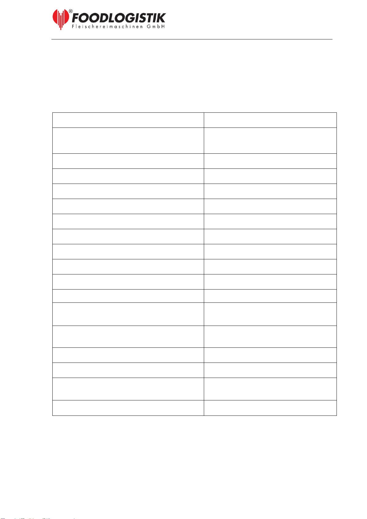
Illustration 1: Machine dimensions ..............................................................................6
Illustration 2: Space requirement of the machine ........................................................6
Illustration 3: Machine overview (1).............................................................................9
Illustration 4: Machine overview (2).............................................................................9
Illustration 5: Cutting set 10x10x10 mm ....................................................................10
Illustration 6: Machine safety switch..........................................................................12
Illustration 7: Control knobs.......................................................................................14
Illustration 8: Open the cutting area...........................................................................20
Illustration 9: Removal of the cutting sets..................................................................20
Illustration 10: Removal of the cutting drum ..............................................................21
Illustration 11: Removal of the scraper......................................................................21
Illustration 12: Removal of the infeed drum and the bearing bush.............................22
Illustration 13: Removal of the separating knife assembly.........................................23
Illustration 14: The separating knife assembly...........................................................23
Illustration 15: The cutting area.................................................................................27

REGISTER OF TABLES
05/09/23 ShreddR®- classic 140 5
REGISTER OF TABLES Page
Table 1: General parameters.......................................................................................5
Table 2: Electrical parameters.....................................................................................7
Table 3: Cutting set sizes..........................................................................................11
Table 4: Control knobs..............................................................................................15
Table 5: Functions test..............................................................................................16
Table 6: General work flow........................................................................................17
Table 7: Cleaning plan ..............................................................................................25
Table 8: Inspections- and maintenance plan.............................................................29

SAFETY
05/09/23 ShreddR®- classic 140 2
1 SAFETY
1.1Symbols and meanings
a) Work place safety symbol:
This symbol indicates a warning to personal safety, and or risk
to bodily injury. When this symbol appears follow all
instructions and inform others of any safety guidelines given.
b) Attention:
ATTENTION
This is a system malfunction indication and denotes that
general maintenance may be required. When this symbol
appears refer to instruction and operation guidelines to ensure
that all operating procedures have been properly followed to
reduce the risk of repairs.
c) Information:
This symbol denotes information relating to the economic use of
the ShreddR - classic 140 or technical requirements that the user
must take into special account.

SAFETY
05/09/23 ShreddR®- classic 140 3
1.2Safety regulations
1.2.1 General safety regulations
The ShreddR - classic 140 is operationally compliant and in accordance with the
requirements set forth in the guidelines of the Council of the European Community
for Machinery (2006/42/EG), along with the current German accident prevention
regulations (UVV/VBG).
Incorrect usage of the ShreddR - classic 140 causes dangers. All users of the
ShreddR - classic 140 must strictly adhere to all technical safety instructions and
regulations established in this manual when installing, and operating this machine.
The following German legislation regulations relating to employee and general work
place safety and or their national equivalents, need to be taken into consideration:
- EN 60204-1:2019-06: Safety of machinery –Electrical equipment of machines -
Part 1: General requirement
- EN 50110-1:2014-02: Operation of electrical installations –
Part 1: General requirements;
- 89/391/EEC - Safety and health of workers - Employer-s duty to ensure the safety
and health of workers in all aspects related to work - Employer-s liability
- 2009/104/EC concerning the minimum safety and health requirements for the use of
work equipment by workers at work
- 2014/35/EC relating to electrical equipment designed for use within certain voltage
limits (Low Voltage Directive)
- guidelines of the respective countries of usage
The safety guidelines set forth in this user manual are universally compliant and
should be followed in order to maintain employee safety, eliminate work place injuries
and be in compliance with the environmental protection agency regulations. All
authorized employees must pass regular inspections and attend monthly training to
maintain compliance to operate this machine.
Only authorized employees may operate the ShreddR - classic 140 and must wear
all required safety gear when operating, maintaining or cleaning this machine.

SAFETY
05/09/23 ShreddR®- classic 140 4
1.2.2 Safety regulations for maintenance and repairs
Changes should never be made to any of the protective equipment/installations when
cleaning or carrying out maintenance. During maintenance and repairs of the
ShreddR - classic 140 the power supply and machine must be in the off position. At
all times authorized workers making repairs or maintaining this machine must wear
the proper safety gear (gloves, goggles, rubber-soled shoes). There may be no
alterations to the machines pre-installed safety features. Any pieces removed from
the machine need to be re-installed and tested to ensure proper working order before
the machine may be re-instated to normal working conditions.
This machine should be in proper working order at all times. Any malfunctions need
to be noted and reported to the appropriate managers. Only trained and authorized
mechanics and technicians (electricians and hydraulic specialists) may service and or
repair any part of this machine. Before making repairs ensure that the dicer is in the
off position, meaning the main switch is off and in the locked position. While making
repairs, at no time may any alterations to the machines pre-installed safety features
be made unless otherwise consented by the machine manufacturer.
After any and all servicing and or repairs, trial runs and safety tests must be made to
ensure proper working order of all machine systems and safety features, before it
may return to the work floor (see 5.1.2).
1.2.3 Safety regulations for operation of ShreddR - classic 140
Before the work day begins, the ShreddR - classic 140 must pass inspection of its
safety systems.
At no times are employees allowed to climb into or on the machine by any means.
While the machine is in operation do not stand in the vicinity or under the loading
arm.
Do not place hands, fingers or arms inside the hopper or under the machine door into
the cutting area, while the machine is running.
While the machine is operating it needs to remain under constant supervision to
ensure that any malfunctions that arise are immediately reported and fixed.
In case of an emergency, shut the machine off by pressing the emergency stop
button on the control panel.
TECHNICAL DATA
05/09/23 ShreddR®- classic 140 5
2 TECHNICAL DATA
2.1General parameters
Table 1: General parameters
Parameter
ShreddR - classic 140
Performance Rate (contingent upon
application, cutting size, usage of infeed
drum and operating staff)
10mm x 10mm cubes, 2000 kg/h
Length [mm] (Illustration 1)
1640
Width [mm] (Illustration 1)
931
Height [mm] (Illustration 1)
1689
Space Requirement [m²] (Illustration 2)
2,5
Weight [kg]
300
Width of drum [mm]
140
Diameter of drum [mm]
320
Diameter fill opening [mm]
144
Equivalent sound pressure level
80 dB (A)
Employees Needed
1 Person
Construction Method
corrosion resistant stainless steel
construction and aluminum
Goods to be processed
vegetables, fruits
(–3° C to + 60° C, 27° F to + 140° F)
Cutting sizes
3 to 20 mm
Power Sources
electric
Storehouse: Relative Humidity
max. 93 % at 25° C, 77° F
Operating Conditions: Temperature
+5° C to +25° C , 41° F to 77° F
TECHNICAL DATA
05/09/23 ShreddR®- classic 140 6
Illustration 1: Machine dimensions
Illustration 2: Space requirement of the machine

TECHNICAL DATA
05/09/23 ShreddR®- classic 140 7
2.2 Electrical parameters
Table 2: Electrical parameters
Electrical parameters
1PE / 230 V / 50 Hz
Connected load
1,8 kW
Rated current
10 A
Fuse current
16 A
Type of current
PE
Operating frequency
50 Hz
Operating voltage
230 V
Control voltage
24 V DC
Simultaneousness factor
0,9
Operating mode
Permanent operation
Protective system
IPX 5
Ambient temperature
+5 °C to +25 °C

MACHINE DESCRIPTION
05/09/23 ShreddR®- classic 140 8
3 MACHINE DESCRIPTION
3.1Range of applications
The featured application of this dicer is its ability to cut food. The ShreddR - classic
140 has the ability to cut cubes, stripes or slices from vegetable and fruit products.
Use of this machine in ways other than intended is restricted
and at the risk of the user. The manufacturer is not liable for
any damages incurred due to improper use and or neglect.
3.2Machine assembly
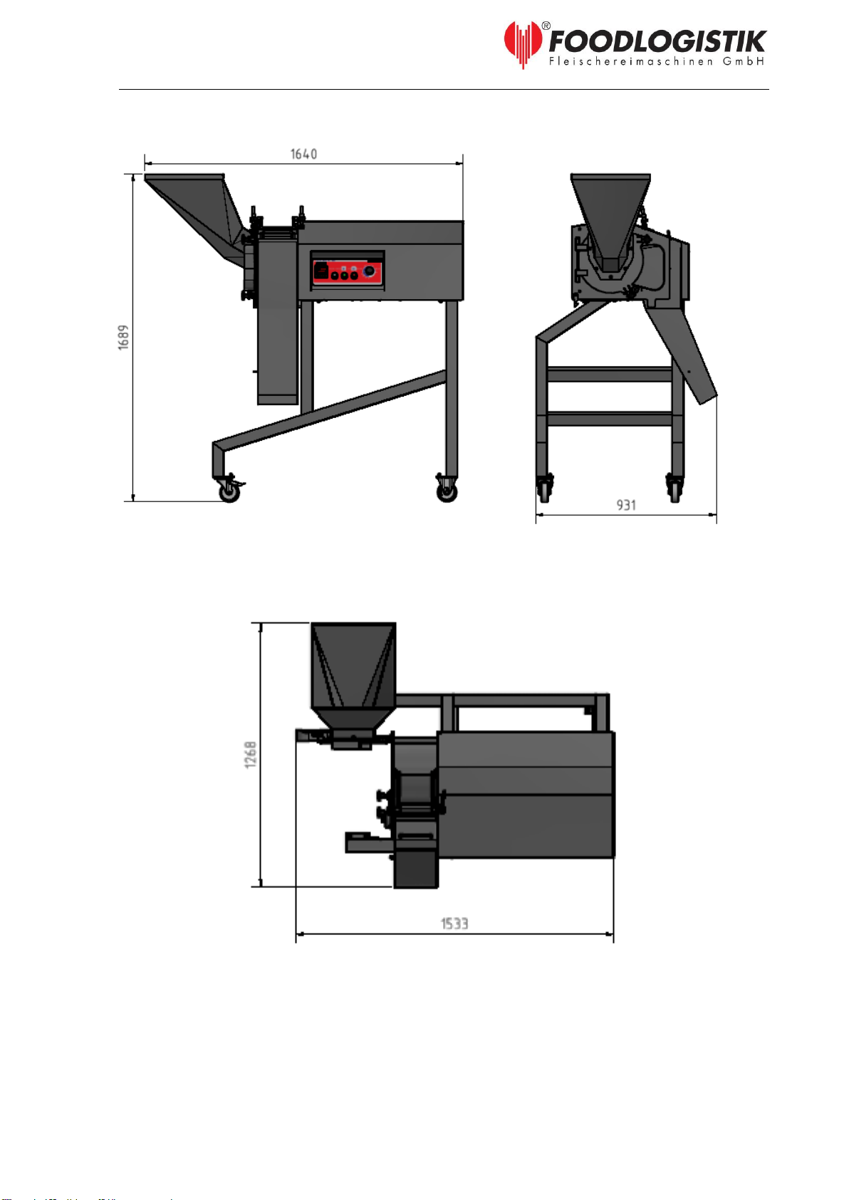
3.2.1 Machine overview
The machine overview is pictorially displayed through illustrations and diagrams. The
ShreddR - classic 140 consists of (view Illustration 3 and Illustration 4):
01 –Frame
02 –Control panel
03 –Product outfeed
04 –Adjustment of cutting-size
05 –Hopper
06 –Upper cover for cutting-area
07 –Cutting area with cutting tools
08 –Cutting-area door
09 –Feet
10 –Infeed drum
MACHINE DESCRIPTION
05/09/23 ShreddR®- classic 140 9
Illustration 3: Machine overview (1)
Illustration 4: Machine overview (2)
05
09
07
03
08
10
06
04
02
01
MACHINE DESCRIPTION
05/09/23 ShreddR®- classic 140 10
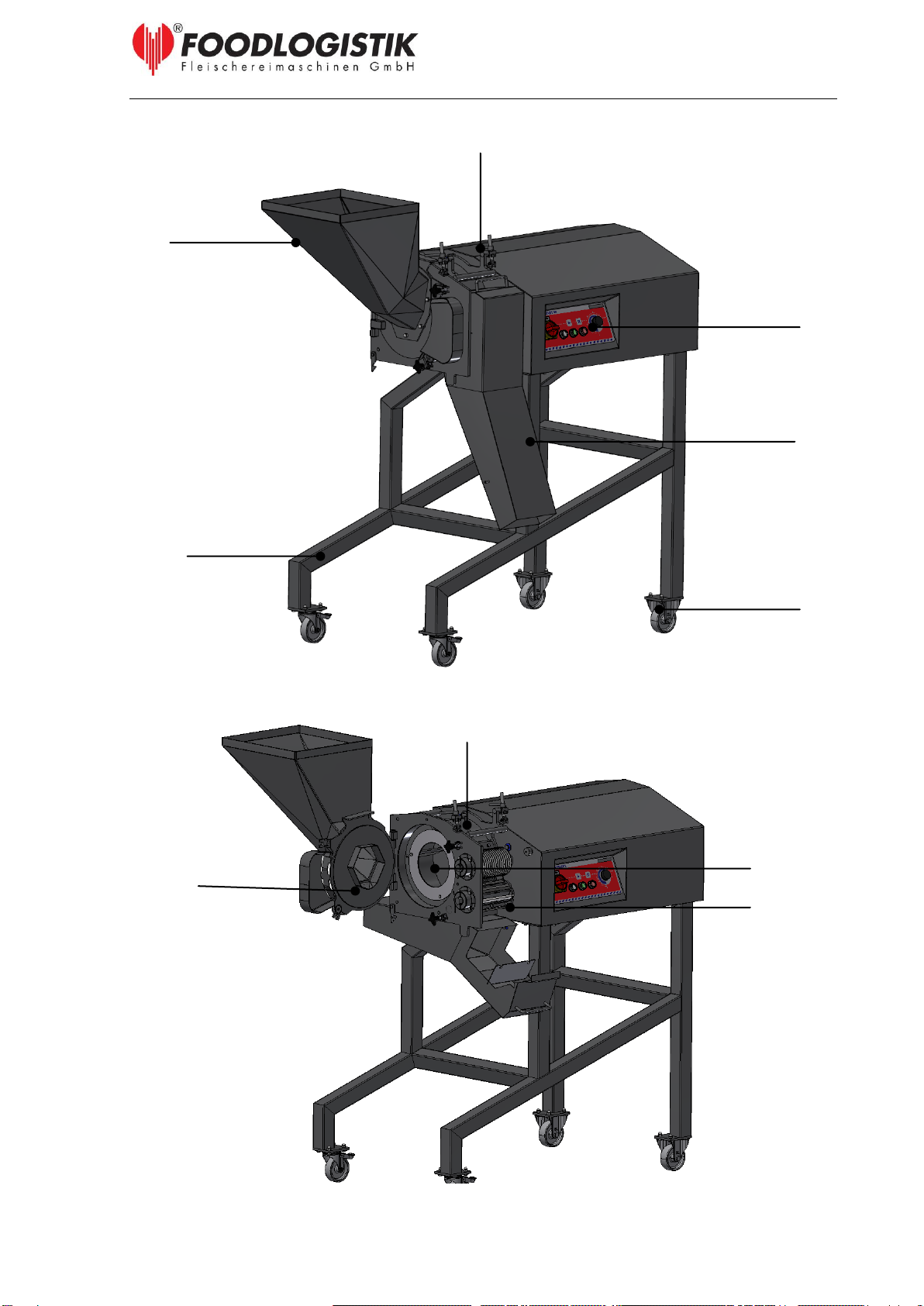
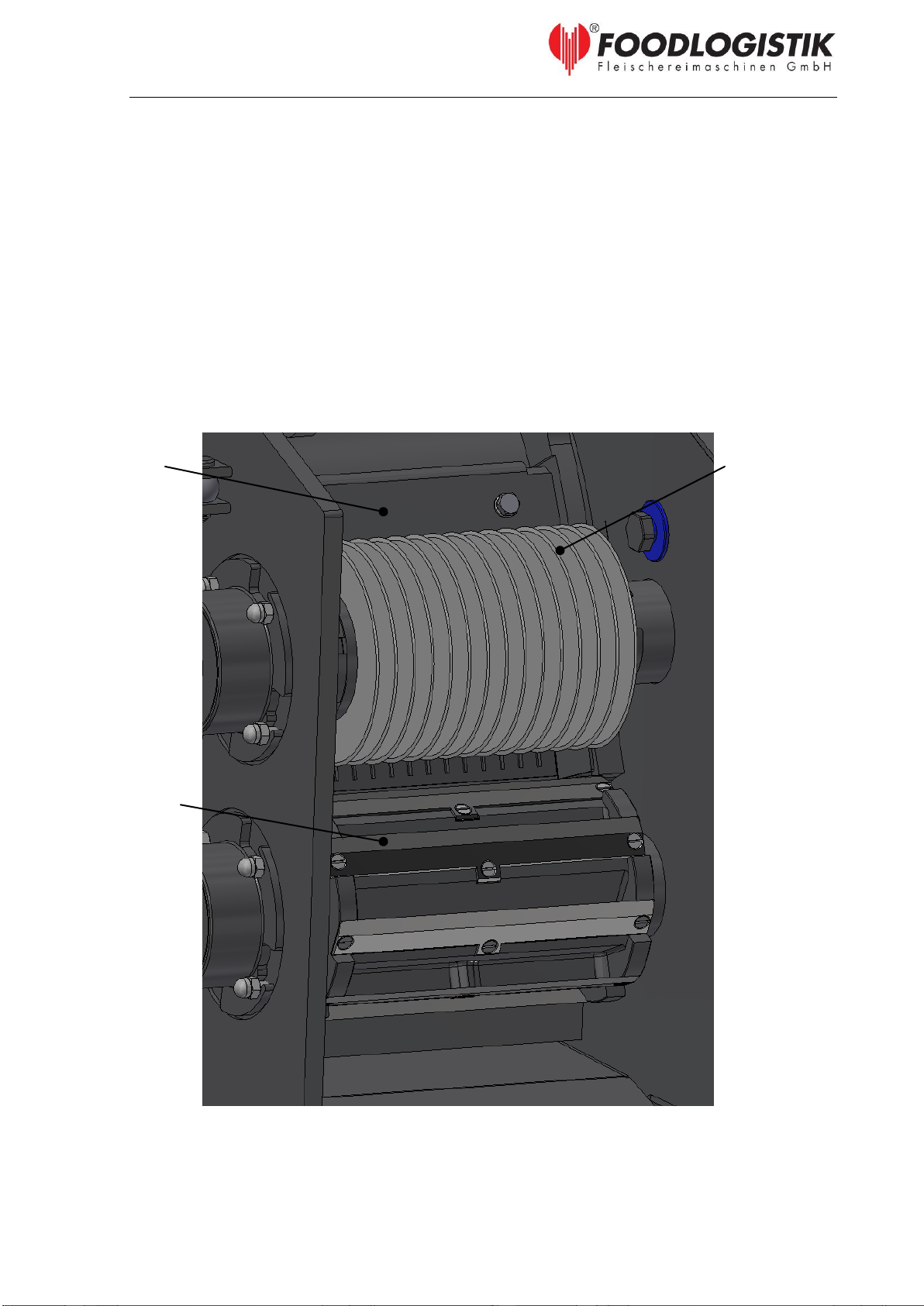
Upper cutting
drum with circular
knives
Lower cutting
drum with cross
cutting knives
Scraper
3.2.2 Cutting tools and accessories
3.2.2.1 Cutting set
The ShreddR - classic 140 can be equipped with optional cutting sets. The cutting set
is depicted in
Illustration 5.
Illustration 5: Cutting set 10x10x10 mm
MACHINE DESCRIPTION
05/09/23 ShreddR®- classic 140 11
FOODLOGISTIK GmbH offers cutting sets in the following sizes:
Table 3: Cutting set sizes
Sizes [mm]
Number of knives
Upper cutting drum with
circular knives
Lower cutting drum with
cross cutting knives
3 x 3
47
30
4 x 4
36
22
5 x 5
29
15
6 x 6
24
13
7 x 7
21
12
10 x10
15
8
12 x 12
13
7
15 x 15
10
6
20 x 20
8
4
MACHINE DESCRIPTION
05/09/23 ShreddR®- classic 140 12
Safety switch
B2
Safety switch
B1
(under the sheet
metal)
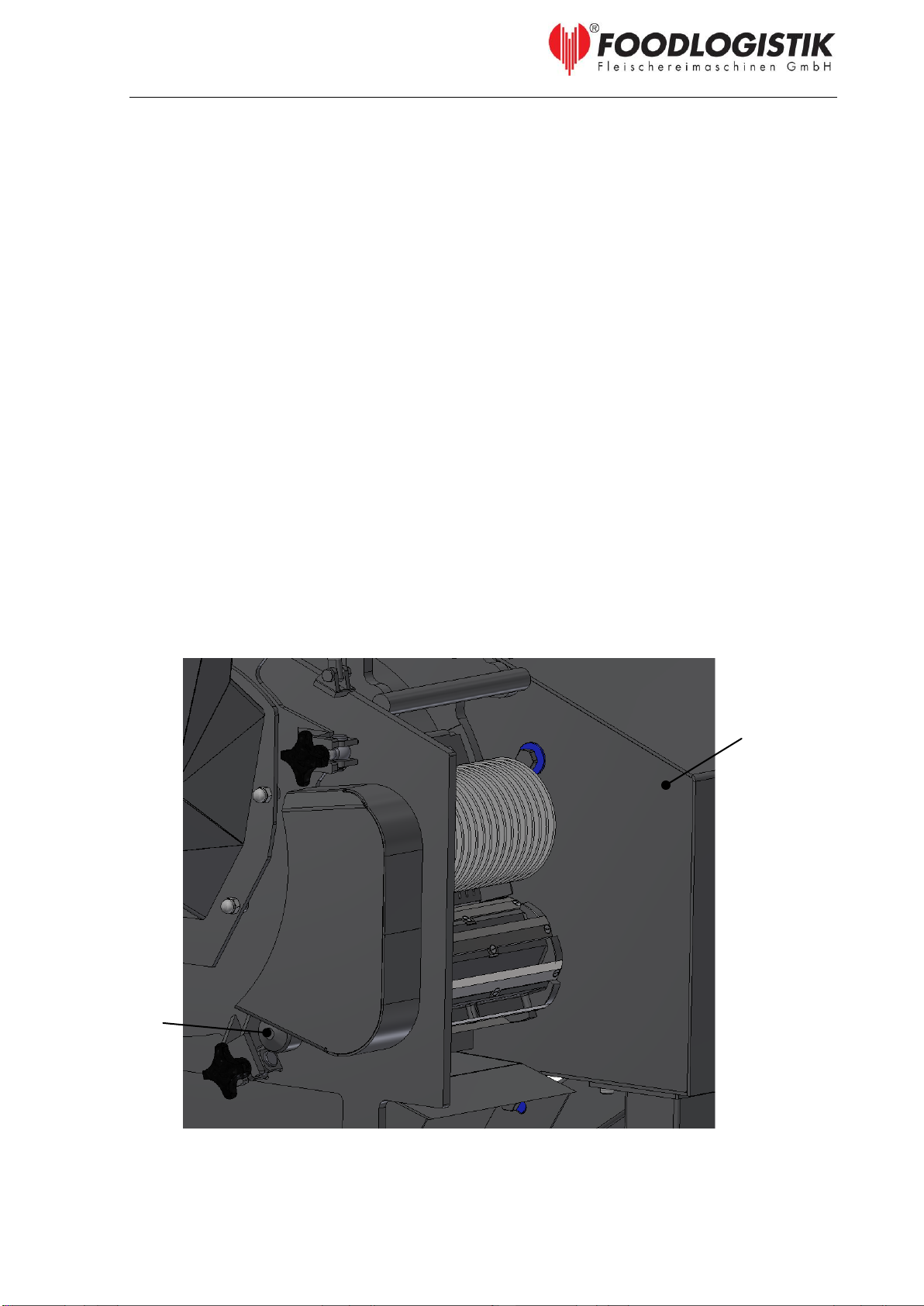
3.2.3 Construction of electrical components
The electrical equipment of the machine consists of electric box, control panel and
electrical parts inside of the machine frame.
a) Electric box
The electric box is the information processing centre for all machine functions. The
electric box houses all the required control elements for this dicer. All safety and
control switches, transformers, fuses, motor protection switches as well as the
terminal strip can be found in this area.
b) Control panel
The control panel is the main operating station for machine functions. Here the
operator is able to control and observe all machine functions.
c) Machine
Inside the machine frame itself is the main driving unit for the cutting tools, safety
switches and the magnetic switches. The arrangement of the safety switches can be
viewed in Illustration 6.
Illustration 6: Machine safety switch

DELIVERY, INSTALLATION AND SET UP
05/09/23 ShreddR®- classic 140 13
4 DELIVERY, INSTALLATION AND SET UP
Delivery, installation and setup of this machine is to be completed by an authorized
Foodlogistik technician or other authorized specialized personnel / Foodlogistik
associate. Foodlogistik is not liable for damages when delivery, installation and setup
of this machine has been completed by someone other than an authorized
Foodlogistik technician.
4.1Transport
Use a hand forklift when unloading this machine and while transporting to work place
station. The machine is to be transported in the upright position.
While transporting on hand forklift, ensure the machine is
firmly situated in the centre of the forks, so that the machine
does not fall. Take care about the electric power cable of the
machine.
4.2Installation
This dicer is only to be used in upright position, in respect to the
load carrying capacities and horizontal level of the facility (see point
2.1).
Test the machine stability and whether every foot is situated firmly on the work floor,
before putting machine into use. Ensure there is sufficient space for the machine
operator (see point 2.1).
This machine under no circumstance be operated on any type
of height adjusting equipment; by installing supports of any
sort, or by installing upon a platform.
4.3Set-up
First, the door and the product outfeed must be installed in the machine (behold
illustration 3).
The ShreddR - classic 140 comes included with a 5 m long power cord. The owner of
the machine needs to ensure that correct voltage and power supply is provided (see
point 2.2 ).
With every start and restart of this machine, there needs to be systems checks to
ensure proper working order of all machine functions. Check the cutting distance of
the cutting sets. After every adjustment made, there needs to be systems safety
checks to ensure proper working order of machine functions (see point 5.1.2).
Table of contents


