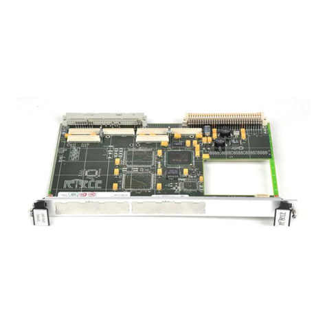
Force Computers SPARC CPU-5CE User manual

-~
ARTISAN
®
~I
TECHNOLOGY
GROUP
Your definitive source
for
quality
pre-owned
equipment.
Artisan Technology
Group
Full-service,
independent
repair
center
with
experienced
engineers
and
technicians
on staff.
We
buy
your
excess,
underutilized,
and
idle
equipment
along
with
credit
for
buybacks
and
trade-ins
.
Custom
engineering
so
your
equipment
works
exactly as
you
specify.
•
Critical
and
expedited
services
•
Leasing
/
Rentals/
Demos
• In
stock/
Ready-to-ship
•
!TAR-certified
secure
asset
solutions
Expert
team
ITrust
guarantee
I
100%
satisfaction
All
tr
ademarks,
br
a
nd
names, a
nd
br
a
nd
s a
pp
earing here
in
are
th
e property of
th
e
ir
r
es
pecti
ve
ow
ner
s.
Find the Emerson / Motorola / Force Computers CPU-5CE/32 at our website: Click HERE

P/N 203510
FORCE COMPUTERS Inc./GmbH
All Rights Reserved
This document shall not be duplicated, nor its contents used
for any purpose, unless express permission has been granted.
Copyright by FORCE COMPUTERS
SPARC/CPU-5CE
Installation Guide
Edition No. 3.0
October 1996

FORCE COMPUTERS Page i
SPARC/CPU-5CE Installation Guide Table of Contents
Table of Contents
1. Introduction................................................................................................1
1.1. Caution.........................................................................................................1
1.2. Location Diagram of the SPARC CPU-5CE Board....................................2
1.3. SPARC CPU-5CE Technical Reference Manual Set..................................2
1.4. Before Powering Up....................................................................................5
1.4.1. Default Switch Settings .............................................................................. 5
1.5. Powering Up................................................................................................8
1.5.1. VME Slot-1 Device .................................................................................... 8
1.5.2. VMEbus SYSRESET Switches.................................................................. 8
1.5.3. Serial Ports.................................................................................................. 8
1.5.4. RESET and ABORT Key Enable............................................................... 9
1.5.5. SCSI Termination....................................................................................... 9
1.5.6. Boot Flash EPROM Write Protection......................................................... 9
1.5.7. User Flash EPROM Write Protection......................................................... 9
1.5.8. Reserved Switches...................................................................................... 9
1.5.9. Parallel Port or Floppy Interface via VME P2 Connector........................ 10
1.5.10. Ethernet via Front Panel or VME P2 Connector..................................... 11
1.6. OpenBoot Firmware ..................................................................................12
1.6.1. Boot the System........................................................................................ 12
1.6.2. NVRAM Boot Parameters........................................................................ 15
1.6.3. Diagnostics ............................................................................................... 16
1.6.4. Display System Information..................................................................... 19
1.6.5. Reset the System....................................................................................... 20
1.6.6. OpenBoot Help......................................................................................... 20
1.6.7. How to Install an OpenBoot ROM........................................................... 22
1.7. Front Panel.................................................................................................23
1.7.1. Features of the Front Panel....................................................................... 24
1.8. SPARC CPU-5CE Connectors..................................................................25
1.8.1. Ethernet Connector Pinout........................................................................ 26
1.8.2. Serial Ports A and B Connector Pinout .................................................... 27
1.8.3. Keyboard/Mouse Connector Pinout ......................................................... 28
1.8.4. VME P2 Connector Pinout....................................................................... 29
1.8.5. The IOBP-10 Connectors ......................................................................... 31
1.9. How to Determine the Ethernet Address and Host ID ..............................38
1.10. Publication History of the Manual.............................................................39

Table of Contents SPARC/CPU-5CE Installation Guide
Page ii FORCE COMPUTERS

FORCE COMPUTERS Page iii
SPARC/CPU-5CE Installation Guide List of Figures
List of Figures
Figure 1. Diagram of the CPU-5CE ...........................................................................3
Figure 2. Highlighted Diagram of the CPU-5CE .......................................................4
Figure 3. Parallel Port Interface Via VME P2 Connector ........................................10
Figure 4. Ethernet Interface Availability .................................................................11
Figure 5. Diagram of the Front Panel .......................................................................23
Figure 6. Pinout of theEthernet Cable Connector ....................................................26
Figure 7. Serial Ports A and B Connector Pinout ....................................................27
Figure 8. Keyboard/Mouse Connector .....................................................................28
Figure 9. The IOBP-10 .............................................................................................31
Figure 10. The 48-bit (6-byte) Ethernet address ........................................................38
Figure 11. The 32-bit (4-byte) host ID .......................................................................38

List of Figures SPARC/CPU-5CE Installation Guide
Page iv FORCE COMPUTERS

FORCE COMPUTERS Page v
SPARC/CPU-5CE Installation Guide List of Tables
List of Tables
Table 1. Default Switch Settings .............................................................................. 5
Table 2. Device Alias Definitions........................................................................... 14
Table 3. Setting Configuration Parameters............................................................. 15
Table 4. Diagnostic Routines.................................................................................. 16
Table 5. Commands to Display System Information.............................................. 19
Table 6. Features of the Front Panel....................................................................... 24
Table 7. SPARC CPU-5CE Connectors................................................................. 25
Table 8. Ethernet the Connector Pinout.................................................................. 26
Table 9. Serial Ports A and B Connector Pinout for RS-232 ................................. 27
Table 10. Keyboard/Mouse Connector Pinout ......................................................... 28
Table 11. VME P2 Connector Pinout....................................................................... 29
Table 12. IOBP-10 P1 Pinout................................................................................... 32
Table 13. IOBP-10 P2 Pinout (SCSI)....................................................................... 34
Table 14. IOBP-10 P3 Pinout (Floppy).................................................................... 35
Table 15. IOBP-10 P4 Pinout (Centronics).............................................................. 36
Table 16. IOBP-10 P5 Pinout (Serial)...................................................................... 37
Table 17. IOBP-10 Pinout (Ethernet)....................................................................... 37
Table 18. History of Manual..................................................................................... 39

List of Tables SPARC/CPU-5CE Installation Guide
Page vi FORCE COMPUTERS

FORCE COMPUTERS Page 1
SSPARC/CPU-5CE Installation Guide
1. Introduction
This Installation Guide provides instructions for powering up the SPARC CPU-5CE board.
The Installation Guide, which you have in your hand now, appears both as Section 2 of the
SPARC CPU-5CE Technical Reference Manual and as a stand-alone Installation Guide. This
stand-alone Installation Guide is delivered by FORCE COMPUTERS with every board.
1.1 Caution
To ensure proper functioning of the product over its usual lifetime, take the following precau-
tions before handling the board.
Electrostatic discharge and incorrect board installation and uninstallation can damage circuits
or shorten their lifetime.
• Before installing or uninstalling the board, read this Installation section.
• Before installing or uninstalling the board in a VME rack:
– Check all installed boards for steps that you have to take before turning off the power.
– Take those steps.
– Finally turn off the power.
• Before touching integrated circuits, ensure that you are working in an electrostatic free
environment.
• Ensure that the board is connected to the VMEbus via both connectors, the P1 and the P2
and that power is available on both.
• When operating the board in areas of strong electro-magnetic radiation, ensure that the
board
– is bolted on the VME rack
– and shielded by closed housing.
Read the following safety note before
handling the board.

Installation Guide SPARC/CPU-5CE
Page 2 FORCE COMPUTERS
1.2 Location Diagram of the SPARC CPU-5CE Board
A location diagram showing all the components of the CPU-5CE appears on the next page. On
the page next to it, there is a location diagram of the CPU-5CE which highlights components
that are of particular interest to the user.
1.3 SPARC CPU-5CE Technical Reference Manual Set
Also available from FORCE COMPUTERS is the SPARC CPU-5CE Technical Reference
Manual Set. This set includes the SPARC CPU-5CE Technical Reference Manual as well as
two additional books. The SPARC CPU-5CE Technical Reference Manual provides a
comprehensive hardware and software guide to your board and is intended for those persons
who require complete information. The titles and contents of the two additional books are listed
here:
The Set of Data Sheets for the SPARC CPU-5CE contains the following data sheets.
The OPEN BOOT PROM 2.0 MANUAL SET contains the following three sections.
NCR SBus I/O Chipset Data Manual Sun Microsystems S4 Chip Set (Rev.4)
microSPARC-II Data Sheet AMD Flash EPROM (AM28F020)
SGS-THOMSON MK48T08(B)-10/12/15/20 Intel Flash Memory (28F008SA-L)
Open Boot 2.0 Quick Reference FCODE Programs
Open Boot 2.0 Command Reference

FORCE COMPUTERS Page 3
SSPARC/CPU-5CE Installation Guide
FIGURE 1. Diagram of the CPU-5CE

Installation Guide SPARC/CPU-5CE
Page 4 FORCE COMPUTERS
FIGURE 2. Highlighted Diagram of the CPU-5CE
SW8
Rotary
Switch
SW5 SW9
S4-VME
SBus Slot # 1 at P3
microSPARC-II
NCR89105 NCR89100
SBus Slot # 2 at P4
B3
B1 B2
SW2
USER
EPROM
RTC/
NVRAM
BOOT EPROM
J125 J124
Device # 1 Lower
Device # 2 Upper
B9
B10
B8
SW3
SW4
B5 B4
J5
J6
B6 B7

FORCE COMPUTERS Page 5
SSPARC/CPU-5CE Installation Guide
1.4 Before Powering Up
WARNING: Switch off the power before installing the board into a VME rack.
Before powering up, please make sure that the default switch settings are all set according to
the table below. For the position of the switches on the board, please see the “Highlighted
Diagram of the CPU-5CE” on page 4. Now is an excellent time to examine the switches to
confirm that they are correctly set.
1.4.1 Default Switch Settings
Table 1: Default Switch Settings
Diagram of Switch Switches Default
Setting Function
SWITCH 2
SW2-6
SW2-5
ON
OFF
SCSI termination
ON = enable, OFF = disable
Test Switch, must be OFF
SW2-4
SW2-3
OFF
OFF
User Flash EPROM write protection
ON = disable, OFF = enable
Boot Flash EPROM write protection
ON = disable, OFF = enable
SW2-2
SW2-1 ON
OFF Test Switch, must be ON
Test Switch, must be OFF
SWITCH 3
(Controls Serial Channel A)
SW3-1 ON TRXC on Front Panel Connector for RS-232
ON=Available, OFF=Not Available
SW3-2 OFF RTS functions as TEN for RS-485
ON=TEN function enabled
OFF=TEN function disabled
SW3-3 OFF TRXC +/- on Front Panel Connector for RS-422
ON=Available, OFF=Not Available
SW3-4 ON RTS on Front Panel Connector for RS-232 or
RTS +/- on Front Panel Connector for RS-422
ON=Available, OFF=Not Available
SW3-5 ON CTS on Front Panel Connector for RS-232 or
CTS +/- on Front Panel Connector for RS-422
ON=Available, OFF=Not Available
SW3-6 OFF RTXC +/- on Front Panel Connector for RS-422
ON=Available, OFF=Not Available
SW2
OFF
ON
654 213
SW3
OFF
ON
654 213

Installation Guide SPARC/CPU-5CE
Page 6 FORCE COMPUTERS
SWITCH 4
(Controls Serial Channel B)
SW4-1 ON TRXC on Front Panel Connector for RS-232
ON=Available, OFF=Not Available
SW4-2 OFF RTS functions as TEN for RS-485
ON=TEN function enabled
OFF=TEN function disabled
SW4-3 OFF TRXC +/- on Front Panel Connector for RS-422
ON=Available, OFF=Not Available
SW4-4 ON RTS on Front Panel Connector for RS-232 or
RTS +/- on Front Panel Connector for RS-422
ON=Available, OFF=Not Available
SW4-5 ON CTS on Front Panel Connector for RS-232 or
CTS +/- on Front Panel Connector for RS-422
ON=Available, OFF=Not Available
SW4-6 OFF RTXC +/- on Front Panel Connector for RS-422
ON=Available, OFF=Not Available
SWITCH 5
SW5-2
SW5-1
OFF
ON
Test Switch, must be OFF
VMEbus Slot1 Device
ON = Slot-1 Device, OFF = Not Slot-1 Device
SWITCH 8
SW8-2
SW8-1
ON
ON
Abort Key Control
ON=Abort Key enable, OFF=Abort Key disable
Reset Key Control
ON=Reset Key enable, OFF=Reset Key disable
Table 1: Default Switch Settings (cont.)
Diagram of Switch Switches Default
Setting Function
OFF
ON
654 213
SW4
1
2
SW5
ON OFF
SW8
OFF
ON
1
2

FORCE COMPUTERS Page 7
SSPARC/CPU-5CE Installation Guide
CAUTION: To avoid damaging the serial ports, please consider the following regarding
Switch 3 and Switch 4. Do not set the switches (SW3-1 and SW3-2), or (SW3-3 and SW3-4),
or (SW3-5 and SW3-6) to ON at the same time and do not set the switches (SW4-1 and
SW4-2), or (SW4-3 and SW4-4), or (SW4-5 and SW4-6) to ON at the same time!
SWITCH 9
SW9-2
SW9-1
ON
ON
External VMEbus SYSRESET
ON = VMEbus SYSRESET generates on-board
RESET
OFF = VMEbus SYSRESET does not
generate on-board RESET
VMEbus SYSRESET generation
ON = SYSRESET is driven to VMEbus, if board
is Slot-1 Device
OFF = SYSRESET is not driven to VMEbus
Table 1: Default Switch Settings (cont.)
Diagram of Switch Switches Default
Setting Function
1
2
SW9
ON OFF

Installation Guide SPARC/CPU-5CE
Page 8 FORCE COMPUTERS
1.5 Powering Up
The initial power up can easily be done by connecting a terminal to ttya (serial port A). The
advantage of using a terminal is that no frame buffer, monitor, or keyboard is used for initial
power up, which facilitates a simple start up.
Please see the chapter “Boot the System” on page 12 for more detailed information on booting
the system.
1.5.1 VME Slot-1 Device
The SPARC CPU-5CE can be plugged into any VMEbus slot; however, the default
configuration sets the board as a VME slot-1 device, which functions as VME system
controller. To configure your CPU-5CE so it is not a VME slot-1 device, the default
configuration must be changed so that SW5-1 is OFF.
CAUTION
Before installing the SPARC CPU-5CE in a miniforce chassis, please first disable the
VMEbus System Controller function by setting switch SW5-1 to OFF.
1.5.2 VMEbus SYSRESET Switches
When the SPARC CPU-5CE is a VMEbus slot-1 device, it generates the SYSRESET signal
to the VMEbus. This can be disabled by setting the switch SW9-1 to OFF.
An external SYSRESET generates an on-board RESET in the default switch setting, i.e.,
SW9-2 is ON. When SW9-2 is OFF, the external SYSRESET does not generate an on-board
RESET.
1.5.3 Serial Ports
By default, both serial ports are configured as RS-232 interfaces. It is also possible to
configure both ports as RS-422 or RS-485 interfaces. This optional configuration is achieved
with the special FORCE Hybrids FH-003 and FH-005.
The chapter “Default Switch Settings” on page 5 shows the necessary switch settings for
RS-232 operation, where SW3 controls serial port A and SW4 controls serial port B. Please
check that the switches are set accordingly.

FORCE COMPUTERS Page 9
SSPARC/CPU-5CE Installation Guide
1.5.4 RESET and ABORT Key Enable
To enable the RESET and the ABORT functions on the front panel, set switches SW8-1
(RESET) and SW8-2 (ABORT) to ON.
1.5.5 SCSI Termination
Termination for the SCSI interface is enabled when SW2-6 is ON. This is the default setting.
CAUTION
Before installing the SPARC CPU-5CE in a microforce chassis, please first disable the SCSI
termination by setting switch SW2-6 to OFF.
1.5.6 Boot Flash EPROM Write Protection
Both Boot Flash EPROMs are write protected via the switch SW2-3. When SW2-3 is OFF, the
devices are write protected.
1.5.7 User Flash EPROM Write Protection
The optional User Flash EPROMs are write protected via SW2-4. When SW2-4 is OFF, the
User Flash EPROMs are write protected.
1.5.8 Reserved Switches
SW2-1, SW2-2 , SW2-5 and SW5-2 are reserved for test purposes. SW2-1, SW2-5 and SW5-
2 should always be OFF. SW2-2 should always be ON.

Installation Guide SPARC/CPU-5CE
Page 10 FORCE COMPUTERS
1.5.9 Parallel Port or Floppy Interface via VME P2 Connector
Via a 16-pin configuration switch matrix, it is possible for either the parallel port interface or
the floppy interface to be available on the VME P2 connector.
The default setting enables the floppy interface via the VME P2 connector, with the
configuration switch matrix plugged into B2 and B3. This means, of course, that by default the
parallel port interface is not available via the VMEbus P2 connector.
To enable the parallel port interface via the VME P2 connector, plug the configuration switch
matrix in sockets B1 and B3. The following drawing shows this configuration.
FIGURE 3. Parallel Port Interface Via VME P2 Connector
The switch matrix plugs into connectors B1 and B3 and the parallel port is accessible through
the VMEbus P2 connector.
VMEbus P2
Connector
B2 B3 B1
Switch Matrix
connected to B3 & B1
Enlarged View of CPU-5CE

FORCE COMPUTERS Page 11
SSPARC/CPU-5CE Installation Guide
1.5.10 Ethernet via Front Panel or VME P2 Connector
Via an 8-pin configuration switch matrix, it is either possible for the Ethernet interface to be
available via the front panel or the VME P2 connector. The default configuration provides the
Ethernet through the front panel connector.
In order to have the Ethernet interface accessible via the VME P2 connector, the default
configuration must be changed.
Take a moment to examine the diagram to see how one achieves the desired configuration.
FIGURE 4. Ethernet Interface Availability
By default, the Ethernet interface is available through the front panel with the configuration
switch matrix plugged into connectors B9 and B10.
To configure the Ethernet interface to be accessible from the VMEbus P2 connector, the
configuration switch matrix must be plugged into connectors B8 and B10.
WARNING
When the Ethernet interface is configured via P2, do not connect the Ethernet at the
front panel.
Ethernet
Connector
B9 B10 B8
Connectors
Front Panel
Configuration
Switch Matrix

Installation Guide SPARC/CPU-5CE
Page 12 FORCE COMPUTERS
1.6 OpenBoot Firmware
This chapter describes the use of OpenBoot firmware. Specifically, you will read how to
perform the following tasks.
• Boot the System
• Run Diagnostics
• Display System Information
• Reset the System
• OpenBoot Help
For detailed information concerning OpenBoot, please see the OPEN BOOT PROM 2.0
MANUAL SET. This manual is included in the SPARC CPU-5CE Technical Reference Manual
Set.
1.6.1 Boot the System
The most important function of OpenBoot firmware is booting the system. Booting is the
process of loading and executing a stand-alone program such as the operating system. After it
is powered on, the system usually boots automatically after it has passed the Power On SelfTest
(POST). This occurs without user intervention.
If necessary, you can explicitly initiate the boot process from the OpenBoot command
interpreter. Automatic booting uses the default boot device specified in non-volatile RAM
(NVRAM); user initiated booting uses either the default boot device or one specified by the
user.
To boot the system from the default boot device, type the following command at the Forth
Monitor prompt.
or, if you are at the Restricted Monitor Prompt, you have to type the following:
ok boot
>b
This manual suits for next models
1
Table of contents
Other Force Computers Single Board Computer manuals
Popular Single Board Computer manuals by other brands

National Instruments
National Instruments NI sbRIO-9627 Getting started guide

IBASE Technology
IBASE Technology IB818F-I50 user manual
VIA Technologies
VIA Technologies EITX-3002 user manual
S&T
S&T Kontron QDS-9400 user guide
iWave
iWave iW-RainboW-G33M Hardware user's guide

Vantron
Vantron VT-M2M-C335L user manual
