Force Technology FiGS 2.0 User manual

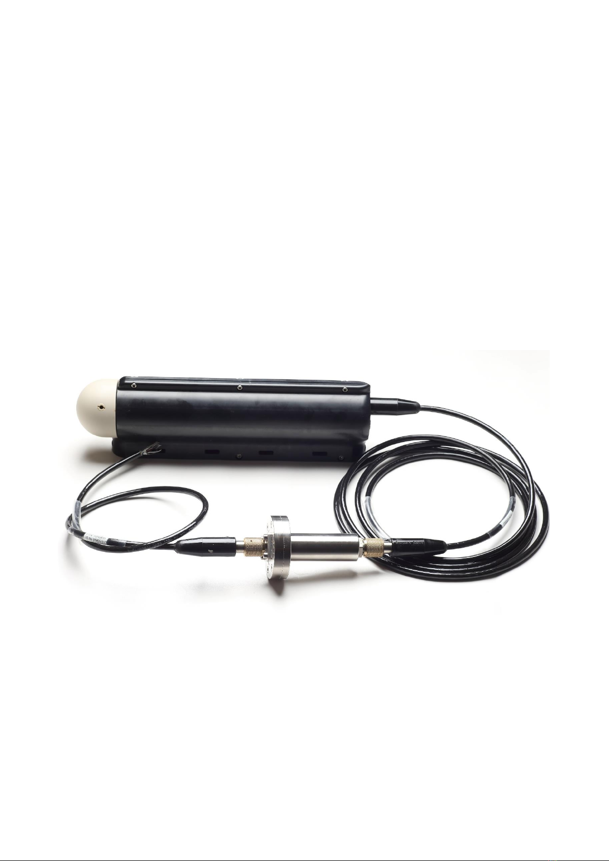
FiGS 2.0 Sensor and Power bottle
User / Service Manual / Quick Guide
Sensor for measurement of electric field gradients in seawater

Manual Nov. 2020 ver. 2 –English
This manual exists in electronic (PDF) and printed format.

EU EMF Statement
FiGS 2.0 is compliant with the requirement for EMF in EU with no separation distance between the user
and/or bystander of the device.
EU Radio equipment intentionally emitting radio waves
Tx Frequency band stated: 2400 MHz to 2483.5 MHz
Technologies stated: Proprietary
Maximum Tx power stated: 0.5μW
USA Statement
Note:
FiGS 2.0 is only compliant if no changes or modifications are made to the device.
FiGS 2.0 is compliant with the requirement for RF exposure in US with <5 mm separation distance between
the user and/or bystander of the device.
FiGS 2.0 has been tested and found to comply with the limits for a Class B digital device, pursuant to Part 15
of the FCC Rules. These limits are designed to provide reasonable protection against harmful interference in
a residential installation. This equipment generates, uses, and can radiate radio frequency energy and, if not
installed and used in accordance with the instructions, may cause harmful interference to radio
communications. However, there is no guarantee that interference will not occur in a particular installation. If
this equipment does cause harmful interference to radio or television reception, which can be determined by
turning the equipment off and on, the user is encouraged to try to correct the interference by one or more of
the following measures:
•Reorient or relocate the receiving antenna.
•Increase the separation between the equipment and receiver.
•Connect the equipment into an outlet on a circuit different from that to which the receiver is
connected.
•Consult the dealer or an experienced radio/TV technician for help.
Canada Statement
Note:
FiGS 2.0 complies with Industry Canada’s license-exempt RSSs. Operation is subject to the following two
conditions:
(1) This device may not cause interference; and
(2) This device must accept any interference, including interference that may cause undesired operation of
the device.
Le présent appareil est conforme aux CNR d’Industrie Canada applicables aux appareils radio exempts de
licence. L’exploitation est autorisée aux deux conditions suivantes:
(1) l’appareil ne doit pas produire de brouillage; et
(2) l’utilisateur de l’appareil doit accepter tout brouillage radioélectrique subi, même si le brouillage est
susceptible d’en compromettre le fonctionnement.

Important Safety and Handling Information
Caution: Changes/modifications not approved by FORCE Technology could void the user’s authority to
operate the equipment.
Disposal and Recycling Information
Please ask FORCE Technology concerning disposal of FiGS 2.0 in your country.

Disclaimer
The information contained in this document is subject to change without notice.
FORCE TECHNOLOGY NORWAY AS MAKES NO WARRANTY OF ANY KIND WITH REGARD TO THIS
MATERIAL, INCLUDING, BUT NOT LIMITED TO, THE IMPLIED WARRANTIES OF MERCHANTABILITY
AND FITNESS FOR A PARTICULAR PURPOSE. FORCE TECHNOLOGY NORWAY AS SHALL NOT BE
LIABLE FOR ERRORS CONTAINED HEREIN OR FOR INCIDENTAL OR CONSEQUENTIAL DAMAGES IN
CONNECTION WITH THE FURNISHING, PERFORMANCE OR USE OF THIS MATERIAL.
Visit our web-site: http://figs.no

Contents
Intended use of the equipment ................................................................................................................ 8
FiGS 2.0 usage .................................................................................................................................... 8
What does FiGS 2.0 measure................................................................................................................ 8
Overview of the sensor ........................................................................................................................ 8
Sensor dimensions ............................................................................................................................. 10
Power bottle dimension...................................................................................................................... 10
Equipment ratings ................................................................................................................................. 11
FiGS 2.0 sensor: ................................................................................................................................ 11
FiGS 2.0 Power bottle: ....................................................................................................................... 12
Equipment installation ........................................................................................................................... 13
Equipment operation ............................................................................................................................. 14
Connecting the sensor to a computer.................................................................................................. 14
Protocol FiGS 2.0 ............................................................................................................................... 14
Formatted messages.......................................................................................................................... 14
Non-formatted messages ................................................................................................................... 15
Protocol details .................................................................................................................................. 15
{SYSTEM}...................................................................................................................................... 16
{R STAT}....................................................................................................................................... 17
{M STAT} ...................................................................................................................................... 17
{VECTOR}...................................................................................................................................... 18
{RAWDMP} .................................................................................................................................... 18
{HALDMP} ..................................................................................................................................... 19
Commands ........................................................................................................................................ 19
How to send commands ..................................................................................................................... 20
Instructions for interconnection to accessories and other equipment, including indication of suitable
accessories, detachable parts and any special materials .......................................................................... 22
Explanations of symbols related to safety which are used on the equipment ............................................. 23
MAINTENANCE ..................................................................................................................................... 29
Cleaning............................................................................................................................................ 29
Regular Maintenance ......................................................................................................................... 30
Integration into systems ........................................................................................................................ 33
Label / Marking for model identification .................................................................................................. 34
On Sensor ......................................................................................................................................... 34
On Power bottle................................................................................................................................. 34

Intended use of the equipment
Note: Use the unit only in the way described in this manual. Failure to follow the guidelines and instructions
in this manual may be dangerous and result in damage to the equipment and erroneous measurements.
FiGS 2.0 usage
FiGS 2.0 is a sensor for measurement of cathodic protection activity and corrosion for assets in seawater,
such as pipelines, subsea structures and fixed installations.
The sensor is mounted on an underwater vehicle, such as a ROV, AUV or ROTV. The sensor is connected
through the vehicle control systems and sensor data is either transmitted topside to a control computer with
logging software or stored locally on the vehicle.
What does FiGS 2.0 measure
FiGS 2.0 measures the electric field gradient in a conductive medium such as seawater. The sensor reports
the electric field gradient vector as two components, FGx and FGy, with the unit µV/cm.
Overview of the sensor
The sensor system consists of:
1. FiGS 2.0 sensor with mounting bracket
2. FiGS 2.0 Power bottle
3. Connecting cable
4. Open-ended connector with pigtail
5. 1 pcs USB memory stick with PC control software and user manual
1
2
3
4

The sensor consists of 3 main parts:
oRotor
oMotor housing
oElectronics housing
The sensor is built up with 3 sensing electrodes mounted on a rotating shaft. The rotating part, from now on
called the rotor, will rotate at a speed of 250 or 500RPM when the sensor is in operation. The motor and
part of the rotor is enclosed in the motor housing, which is oil filled and pressure compensated.
Rotor
Electronics housing

Sensor dimensions
All dimensions are in [mm]
Power bottle dimension

Equipment ratings
FiGS 2.0 sensor:
Supply voltage: 24VDC
Supply current: 3A
Maximum power consumption: 72W
Typical power consumption: 20W
Over Voltage Category I
Data connection: RS 485 full duplex
Connector spec: Transmark TS-FCR-08P-MING-3S
Temperature: -15 / +50C
Pressure 3000MSW / 300barg
Matings +500
Isolation 1000V
Rated voltage 600VDC
Rated current 3.5A
Indoor and outdoor use
Altitude 4000m
Depth 3000m seawater / 300barg
Temperature In air: -15 / 40C
In water: 0 / 40C
Relative humidity: 100%
Contains oil: Panolin HLP SYNTH 15
https://www.panolin.com/
Pollution Degree 2
Dimensions incl. bracket Ø90 x 461mm
Weight in air 5kg
Weight in seawater 2.5kg

FiGS 2.0 Power bottle:
Supply voltage: 21-27VDC
Supply current, full load: 3.4A
Output Voltage 24VDC
Output current: 3A
Over Voltage Category I
Volts, transient, 100 mSec 0-50VDC
Maximum power consumption: 72W
Data connection sensor side: RS 485 full duplex
Data connection computer side: RS 232
Connector spec: Transmark TS-FCR-08P-MING-3S
Temperature: -15 / +50C
Pressure 3000MSW / 300barg
Matings +500
Isolation 1000V
Rated voltage 600VDC
Rated current 3.5A
Indoor and outdoor use
Altitude 4000m
Depth 3000m seawater / 300barg
Temperature In air: -15 / 40C
In water: 0 / 40C
Relative humidity: 100%
Pollution Degree 2
Dimensions Ø90mm x 193mm
Weight in air 1.05kg

Equipment installation
Connect FiGS 2.0 sensor to the FiGS 2.0 power bottle with the supplied cable. Check that the power bottle is
mounted the correct way. The power bottle is marked with “FiGS side” and “ROV side” on the bottle. If the
power bottle is mounted the wrong way, the sensor will fail to power up. Make sure the receptible is clean
and that the O-rings are clean and un-damaged. The O-rings shall be coated with a thin film of silicone-
based O-ring lube. Insert the connector plug into the receptible and tighten the lock ring firmly. For more
permanent installations, a set screw can be used to secure the lock ring.
•Always control the receptible and O-rings for any damage before use. Any failure on the receptable
can damage the sensor. If a receptable has visual damage, the sensor must be repaired. Contact
FTN for service and advice.
•The receptible and connectors shall be clean and free from lint before assembly
•Any damaged O-rings shall be replaced before assembly. Spares can be obtained by contacting
FTN.
•Always check that the cable is free form any visual damage. Any damage to the supplied cable can
lead to failure of the sensor. A damaged cable shall be replaced before use. Spare cables can be
obtained by contacting FTN.
Connect the power bottle to the preferred interface, e.g. ROV or AUV. The receptable on the power bottle
has 8 pins. The pinout is:
oPin1: NC
oPin2: NC
oPin3: NC
oPin4: RS232 RX
oPin5: RS232 TX
oPin6: RS232 GND
oPin7: 0V power
oPin8: +24V power
Either use the supplied pigtail to make the appropriate connection to the ROV / AUV connector panel or
contact FTN for supply of a custom cable.
Receptable O-rings
Part No.: 213118

Figure 1 Pinout on connector
Before use, soak the electrode cotton plugs with 3.5wt% salt water (Clean tap water mixed with 3.5wt%
NaCl)
Equipment operation
Connecting the sensor to a computer
Connect the sensor to the computer via the RS232 interface. The sensor can be controlled by a terminal
software, such as Putty, or by a specific logging and control software.
Protocol FiGS 2.0
FiGS can communicate over RS-232 at 19200, 115800 and 1000000 baud. The communication is ASCI
based, i.e. all messages sent or received are in the ASCI format. There are two message types from FiGS:
formatted messages and non-formatted messages.
Formatted messages
Formated messages starts with {XXXXXX} and ends with [YYY]. These messages are meant to be parsed by
a computer. XXXXXX are always 6 characters long and describes the content of the message. An example is
{SYSTEM} which contains system settings. A formatted message always ends with [YYY] where YYY is the
length of the formatted message, excluding the {XXXXXX} and [YYY].
An example of a formatted message is:
{VECTOR} x: 0.470132 y: -0.755581 E: -6623.961971 xa: -0.020 ya: -0.963 za:-0.086 len: 921[82]
This message is of the type “vector” and is 82 characters long. Values in the message are described with a
name followed by “:” followed by “space” and then the value. Different values are separated by tab (\t) or
newline (\n). NB! A formatted message may contain the newline character (\n). This is to make the
1
8
4
5

messages easier to read in a terminal window. NB! (\n) cannot be used as a terminal character when
reading from the serial port.
Non-formatted messages
In addition to the formatted messages, FiGS also prints loose text. This is intended to be read by humans
and should not be parsed by a computer.
Protocol details
The following messages are defined:
{SYSTEM} system settings
{R STAT} rotor electronics status
{M STAT} motor electronics status
{VECTOR} measurement values
{CMDACK} command acknowledge
{RAWDMP} raw signals from rotor
{HALDMP} Hall sensor values from motor

{SYSTEM}
System contains the following parameters, separated by tab (\t) or newline (\n)
id: 1835060 A unique number identifying the master processor
digital filter: 1 System settings for digital filter (50Hz Cut-off). 0 is off, 1 is on
digital AC: 1 System settings for digital AC filter. 0 is off, 1 is on
mute vectors: 0 0 sends all vector data, 1 mutes the vector data
menu active: 1 1 activates the menu and allows you to send short commands for start, stop
and help menu. 0 deactivates the menu
50hz filter: 1 50Hz analogue filter. 0 deactivates and 1 activates
220nf cap: 0 Filter for active pipe-tracker, e.g. TSS440. 0 deactivates, 1 activates
100x gain: 1 Gain setting on FiGS 0 is 10x gain and 1 is 100x gain
rotor state: 1 1 is measure, 2 is impedance
motor state: 0 Motor state, 0 is off, 1 is on
no rotation mode: 0 0 no-rotation mode deactivated, 1 no-rotation mode active
electrode distance: 7.00 Distance between electrodes in [cm]
use dir cal: 1 Direction calibration: 0 deactivated, 1 active
dir cal: -72.13 active direction calibration angle
use level calibration: 1 Level calibration, 0 is deactivated, 1 is active
level calibration: 147.79 Level calibration angle
use mounted angle: 1 use mounted angle, 0 is deactivated, 1 is active
mounted angle: 147.71 mounted angle
target RPM: 500 system target RPM
use relative cal: 1 use relative cal, 0 is deactivated, 1 is active
relative cal deg: 41.135 relative cal. angle
relative cal amp: 1.053 relative cal. amplitude
use absolute cal: 1 use absolute calibration, 0 is deactivated, 1 is active
absolute cal factor: 1.010 absolute calibration factor
use geometry factor: 1 use geometry factor, 0 is deactivated, 1 is active
geometry factor: 0.714 geometry factor value

auto gain lower: 6 auto gain lower limit
auto gain upper: 85 auto gain upper limit
auto gain enabled: 1 auto gain, 0 is deactivated, 1 is active
master version: 0.9.2 Master software version
{R STAT}
{R STAT} contains the following parameters, separated by tab (\t) or newline (\n)
id: 4653098 A unique number identifying the rotor processor
hum: 31.12 Relative humidity
temp: 28.16 Rotor temperature in °C
5.5 volt: 5.4 5.5 volt value
supply volt: 24.32 supply voltage
rotor state: 1 rotor state, 1 is measure, 2 is impedance
50hz filter: 1 50Hz filter. 1 is enabled, 0 is 500Hz enabled
220nf cap: 0 Pipetracker filter. 1 is enabled, 0 is disabled
100x gain: 1 Gain settings. 0 is 10x, 1 is 100x
version: 0.9.0 Rotor software version
{M STAT}
{M STAT} contains the following parameters, separated by tab (\t) or newline (\n)
id: 2883615 A unique number identifying the motor processor
hum: 43.56 Relative humidity
temp: 28.54 Motor temperature in °C
accel x: 1.03 Inclinometer x-value
accel y: 0.01 Inclinometer y-value
accel z: -0.01 Inclinometer z-value
motor current: 11 motor current
coil current: 0.17 coil current
coil voltage: 27.94 coil voltage
5 volt: 4.33 5.5 volt value

24 volt: 23.68 24 volt value
target rpm: 0 target motor speed
actual rpm: 0.00 actual motor speed
average rpm: 0.00 average motor speed
std rpm: 0.00 standard deviation motor speed
min rpm: 0.00 minimum motor speed
max rpm: 0.00 maximum motor speed
throttle: 0 throttle
comm angle: 0.000000 commutation angle
use stored CA: 0 use stored commutation angle, 1 is enabled, 0 is disabled
version: 0.9.0 motor software version
motor phase current: 0.03 motor phase current
{VECTOR}
{VECTOR} contains the following parameters, separated by tab (\t)
x: 0.470132 Measurement value x-component
y: -0.755581 Measurement value Y-component
E: -6.961971 Electrode polarization
xa: -0.020 Inclinometer x-value
ya: -0.963 Inclinometer y-value
za:-0.086 Inclinometer z-value
len: 922 Received bytes from rotor
{RAWDMP}
{RAWDMP} contains raw measurements from the rotor. {RAWDMP} is followed by 10 values separated by
newline (\n)
-336.621908
-336.621651
-336.621422
-336.621190
-336.620852

-336.620497
-336.620268
-336.620156
-336.619807
-336.619441
{HALDMP}
{HALDMP} contains hall sensor samples. {HALDMP} contains the following parameters separated by tab (\t)
H1raw: 1305 Sample from hall sensor 1
H2raw: 2029 Sample from hall sensor 2
Commands
The following commands are available. A command always starts with ‘#’
Arguments are called with commas in between as in the example below:
#set motor speed,250<ENTER>
set motor speed - 1 argument: 250/500 RPM
use stored comm angle - 1 arg: 1 use comm angle stored in motor memory, 0 to calculate in ramp
store comm angle - Store the current communation angle in memoery
norot - 1 arg: 1 to start no rotation mode, 0 to stop
direction calibration - Perform direction calibration (requires the sensor to run)
level calibration - Perform level calibration when the sensor is perfectly leveled
mounted calibration - Perform level correction when the sensor is mounted
use dircal - 1 arg: 1 to enable direction calibration, 0 to disable
use levelcal - 1 arg: 1 to enable level calibration, 0 to disable
use mounted angle - 1 arg: 1 to use the mounted andgle correction, 0 to disable it
set rotor mode - 1 or 2 args: arg 1: measure/counting/impedance
if 1st arg is impedance a 2nd arg is expected for frequency (float)
use digital filter - 1 arg: 1 to enable digital 50hz fitler coupling, 0 to disable it
use digital ac - 1 arg: 1 to enable digital AC coupling, 0 to disable it

set pt filter - 1 arg: 1 220nf cap in pipetracker filter, 0 for 10nf
set filter - 1 arg: 1 for cutoff at 50hz, 0 for cutoff at 500hz
set gain - 1 arg: 1 for high gain (100), 0 for low gain (10)
mute vectors - 1 arg: 1 mutes vectors, 0 unmutes them
mute status - 1 arg: 1 mutes status messages, 0 unmutes them
electrode distance - 1 arg: X (float), set the electrode distance to X
raw dump - 1 arg: Dump the last X raw data
hall dump - Dump the last 900 hall samples
menu - 1 arg: 1 enables the menu, 0 disables it
motor run - 1 arg: "start" starts the motor, "stop" stops it
rotor power - 1 arg: 1 turns on the rotor, 0 turns it off
set control - 2 args, arg 1: k/p/i, arg 2: value
set baud - 1 arg,: "low": 19200 "medium": 115200 "high": 1000000
save - 1 arg, X: Save current settings to slot X (0-4)
load - 1 arg, X: load settings from slot X (0-4)
erase - 1 arg, X: erase settings at slot X (0-4)
rotor relative cal - 2 args, arg1: Deg, arg2: Amplitude, stores calibration with current settings
use rotor relative cal - 1 arg: 1 to use rotor relative calibration (if available), 0 to ignore rotor
relative calibration
rotor absolute cal - 2 args, arg 1: measured voltage (micro volts), arg 2: rms/amp/pp
use rotor absolute cal - 1 arg: 1 to use rotor absolute calibration (if available), 0 to ignore rotor
absolute calibration
use geometry factor - 1 arg: 1 to enable geometry factor correction, 0 to disable it
set geometry factor - 1 arg: geometry factor
set figs type - 1 arg: fat/slim
How to send commands
Commands can be sent by typing the commands in the terminal window. The other option is to use a
computer program to send the command. To send a command, one must send one and one character, not a
Table of contents
Popular Accessories manuals by other brands

System Sensor
System Sensor 2251CTLE Installation and maintenance instructions

ASTECH
ASTECH LDM41E user manual

PCB Piezotronics
PCB Piezotronics 357E93 Installation and operating manual

Crown
Crown PIP-FTE reference guide

ENFORCER
ENFORCER E-936-S35RRGQ manual

Bumbleride
Bumbleride car seat cover Product guide