FORD HIGGINS POWERFRAME User manual


INSTALLATION GUIDE
·
Power{P[J'@JfJflU®
MicrocomputerSystems
4755 Walnut Street
Boulder, Colorado 80301
(303) 449-8803
TLX:
752267 FHL BLDR
TWX:
910-997-0429
EASYLINK: 62317580
PART
NO.
20224600

Contents
PAGE
1
•••••••••••••
Inspecting
2
•••••••••••••
Unpackaging
3
•••••••••••••
Removing
Unit
from
Box
4
•••••••••••••
Removing
Styrofoam
Frame
5
•••••••••••••
Attaching Bezels
6
•••••••••••••
Plugging in Unit
7•• :
••••••••••
Connecting Console
8.~
•••••••••••
Checking Switches
9
•••••••••••••
Turning
Power
On
10
•••••••••••••
Checking Indicator Lights
11
•••••••••••••
Setting
Switches
12
•••••••••••••
Booting
System
13
•••••••••••••
Unlocking
Heads
{Double-wide systems only)

March
20,
1984
REGARDING:
PROBLEM:
SOLUTION:
NOTE:
Technical
Bulletin
No.
1
Booting
System
When
the system responds:
START?
and
you
type in:
NO,
th~
system responds again with:
START?
When
the system responds:
START?
type in: N instead of
NO.
For
your
own
convenience, please
make
note of
this
in your
Installation
Manual.

March
20,
1984
REGARDING:
PROBLEM:
SOLUTION:
NOTE:
Technical Bulletin
No.
2
Booting
System
When
the system
is
booted to
unit
DMI
(fixed) without a formatted
cartridge
in
unit
DMO,
the system will "hang."
Do
not boot a
DMI
(fixed) disk unless
there
is
a formatted
cartridge
in
DMO.
For
your
own
convenience, please
make
note of t.his in your
Installation
Manual.

March
20,
1984
REGARDING:
PROBLEM:
SOLUTION:
NOTE:
Technical Bulletin
No.
3
RSTS/E
Password
Some
users
have
experienced
difficulty
when
trying
to log
into
account 1,2
on
the
RSTS/E
distribution.
The
password
is:
LIBRA.
For
your
own
convenience, please
make
note of
this
in your
Installation
Manual.

FCC
Compliance
This
equipment
generates
and
uses radio frequency energy
and
if
not
installed
and
used
properly,
i.e.,
in
strict
accordance with
the operating
instructions,
reference manuals,
and
the service
manual,
may
cause interference to radio or
television
reception.
It
has
been
tested
and
found
to
comply
with the
limits
for a
Class A
computing
device pursuant to Subpart J
of
Part
15
of
FCC
Rules,
which
are designed to provide reasonable protection
against
such
interference
when
operated in a
commercial
installation.
If
this
equipment
does cause interference
to
radio
or television reception,
which
can
be
determined
by
turning the
equipment
off
and
on, the user
is
encouraged
to
try
to correct
the interference
by
one
or
more
of
the following measures:
1)
· Reorient the receiving antenna.
2)
Relocat~
the
equipment
with respect
to
the receiver.
3)
Move
the
equipment
away
from
the receiver.
4)
Plug
the
equipment
into a
different
outlet
so
that
equipment
and
ireceiver are
on
different
branch
circuits.
If
necessary, consult your dealer service representative for
additional suggestions.
The
manufacturer
is
not responsible for
any
radio or
TV
interference caused
by
unauthorized modifications to
this
equipment.
It
is
the
responsibility
of
the user to correct
such
interference.

Inspecting
Inspect
box
for
any
damage.
,
.....................
P---------~~~~~~~~~~__;;-..........:i........
-............."""~~~~~~~~~~~~~--~-............~
1

Unpackaging
Open
top
of
box.
Remove
power
cable,
manuals,
and
front
and
back
bezels
(wrapped
in styrofoam)
from
cardboard
shelf.
f',,.ont
4
0.;,c.K
6~u.ls
("'"'Pp•d
;,,
•tyrofoorn)
Remove
cardboard shelf.
2

Removing Unit
Carefully lay the
box
down
on
its
side.
CAUTION:
The
weight of the unit
is
approximately
100
pounds.
The
unit
is
packed
in a styrofoam shipping
frame. Carefully slide the
unit
and
styrofoam out
of
the
box.
3

Removing Styrofoam
Tip
unit
upright.
:
...
Remove
styrofoam shipping frame.
4

Attaching
Bezels
Attach the front
and
back
bezels to the
unit
as
shown
in the
illustrations.
,,,.-----.,._
__
---
:
)-
-
-----
-----
-
-
-~
-iii
----
....
-lll
:l -
1~
[][)[]
-
-
--
---II'
Froflt
of
Un.rt
5

Plugging
In
Unit
Ensure
that
the
power
switch
on
the
back
of
the unit
is
in the
OFF
position ("O").
Then
plug
one
end
of
the
power
cable into the
back
of
the unit
and
the other
end
into a wall
socket.
Power
Switch
0"'0FF
J. =
°"'
~::·:::~
®
Power- Cable
6
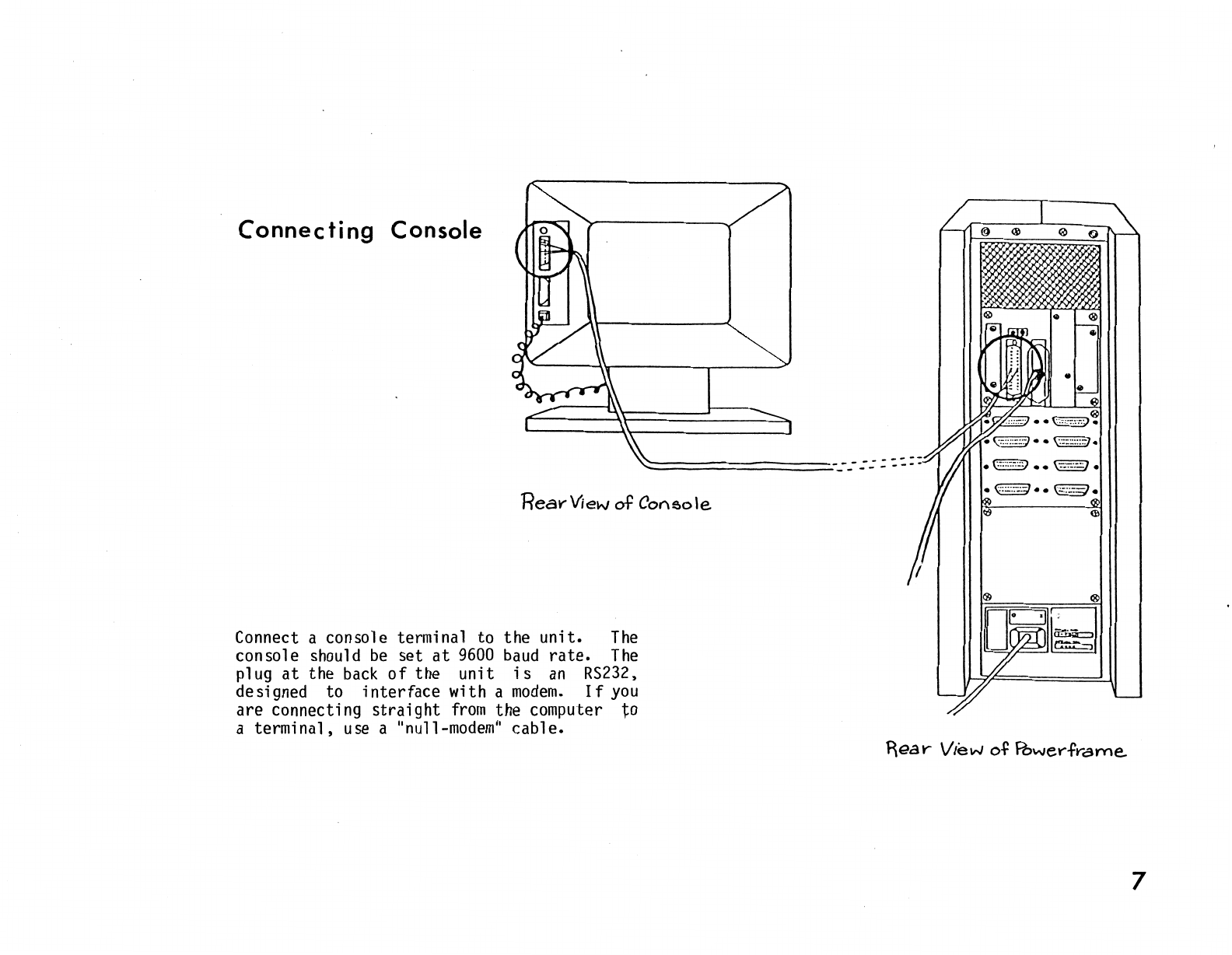
Connecting
Console
Rear-View
of
Cot'\sole
Connect a console terminal to the
unit.
The
console should
be
set
at
9600
baud
rate.
The
plug
at
the
back
of
the unit
is
an
RS232,
designed to interface with a
modem.
If
you
are connecting
straight
from
the computer to
a terminal,
use
a
"null-modem"
cable.
7

Checking
Switches
Check
the switches
below
the disk door
on
the
front
of
the unit.
Make
sure
that
the three
switches
(POWER,
BOOT,
RUN/HALT)
are in the
OFF
position,
which
is
down.
The
disk
START/STOP
switch (to the
left
of
the disk
door)
should
be
in the
STOP
position
and
the
WRITE
PROTECT
switch
(directly
above)
should
be
in the
OFF
position.
r
-I
I I
--
8

Turning Power.On
Turn
the
POWER
switch, located
on
the
back
of
the
unit,
to the
ON
{
11
1
11
) position.
9

Checking
Indicator
Lights
Turn
the
POWER
switch
on
the
front
of
the
unit
to
the
ON
position.
The
POWER,
LOAD,
DC
ON,
and
RUN
lights
on
the
front
of
the
unit
should
light
up.
The
system
will
arrive
with
the
disk
cartridge
already
inside,
so
no
insertion
is
necessary.
,
-~~
,,,
-~~
,~
I
-
-
10

Setting
Switches
After the terminal
is
plugged
in,
put the
RUN
switch
(on
the-front
of the
unit)
in the
RUN
position.
Also,
set
the
START/STOP
switch
(to the
left
of the disk door) to
START.
The
LOAD
light
will extinguish
when
the disk
begins to spin.
The
READY
light
will
illuminate
when
the system
is
ready to boot.
/ II
-~--
i'UWC-.
0
L<MO
;'t
0
.......
TI!
f'1\<1T"(J:T
I 1 '
-
L;
-
11

Booting
System
Depress the
BOOT
switch
(on
the
front
of the
unit)
momentarily.
On
the console screen,
the message:
TESTING
MEMORY
will
appear.
After the
memory
test,
the system
will
respond with the
amount
of
memory
listed
in
the format:
XXX.KW
on
the following
line.
Then
the system will ask:
START?
To
answer,
type in
either:
Y or
DMn
("n"
representing
the
unit
to
be
booted).
The
removable
portion
of
the disk
is
unit
.0';
the fixed
portion
is
unit
1.
NOTE:
Do
not boot a
DMl
(fixed)
disk
unless
there
is
a formatted
cartridge
in
DM@.
The
system
should
now
be
booted
up
and
ready
for use.
( I I
( I I I I
( I I I I
T
fS:
TI
Nl~
Mf/'1(1/;:Y
XXX.l<'I./
I I I I I I I I
I I I I I I I I I
I l I I I I I I I
STARP
Y
I I I I I I I I I
I I I I I I I I I
I I I
~
I I I I I
rrn11111111111111111
11
LilJllllllllllllllllllll
(I
1111JJJ11
111111!I11
I
I)
( .
)
)
)
12

Unlocking Heads
(Double-wide
Systems
Only} -
--
@)lw··
- - -
--
FLATHEAD <P,,,,.. - -- - -
~~£W.5
"'
FRONT
PAt-.!EL-
BOAR.
D
----+-14--i-llli
The
following procedure for unlocking the
heads should only
be
performed
after
the
computer has
been
positioned in place,
and
before
it
has
been
plugged
in.
Do
not
move
the computer
after
the heads
have
been
unlocked, as
damage
may
occur
to
the disk
drive.
·
STEP
1:
Remove
the four flathead screws
located
on
the front
panel
board.
@J'Ji"'
v~·~
fLAIH€AD
s:!,.RcWS
DOUBLE-wt
DE-
PowE.RFf<'AME...
F~ONT
\J\E.W
13
Other manuals for POWERFRAME
1
Table of contents
Popular Computer Hardware manuals by other brands


Blackrock Microsystems
Blackrock Microsystems Cerebus Instructions for use

American Megatrends
American Megatrends MegaRAID Enterprise 1600 quick hardware installation guide

Texas Instruments
Texas Instruments TUSB1004EVM user guide

ZALMAN
ZALMAN CNPS7000C-Cu/AICu user manual

Renesas
Renesas SH7262 Series Hardware Design Guide

ZALMAN
ZALMAN FS-V7 user manual