foris TwinFresh Expert RA1-50 V.3 User manual

TwinFresh Expert RA1-50 V.3
TwinFresh Expert RA1-50 C1 V.3
TwinFresh Expert RM1-50 V.3
Single-room reversible energy recovery ventilator
USER’S MANUAL

2
TwinFresh Expert RA/M1-50 (C1) V.3
Safety requirements..................................................................................................................................................................... 2
Purpose................................................................................................................................................................................................ 4
Delivery set........................................................................................................................................................................................ 4
Designation key.............................................................................................................................................................................. 4
Technical data.................................................................................................................................................................................. 5
Design and operating principle ........................................................................................................................................... 6
Mounting and set-up.................................................................................................................................................................. 8
Connection to power mains .................................................................................................................................................. 12
Technical maintenance.............................................................................................................................................................. 17
Troubleshooting............................................................................................................................................................................. 19
Storage and transportation regulations.......................................................................................................................... 19
Manufacturer’s warranty........................................................................................................................................................... 20
Certificate of acceptance.......................................................................................................................................................... 23
Seller information.......................................................................................................................................................................... 23
Installation certificate.................................................................................................................................................................. 23
Warranty card................................................................................................................................................................................... 23
This user’s manual is a main operating document intended for technical, maintenance, and operating staff.
The manual contains information about purpose, technical details, operating principle, design, and installation of the
TwinFresh Expert RA/M1-50 (C1) V.3 unit and all its modifications.
Technical and maintenance staff must have theoretical and practical training in the field of ventilation systems and should be able to
work in accordance with workplace safety rules as well as construction norms and standards applicable in the territory of the country.
CONTENTS
All user’s manual requirements as well as the provisions of all the applicable local and national
construction, electrical, and technical norms and standards must be observed when installing
and operating the unit.
Disconnect the unit from the power supply prior to any connection, servicing, maintenance, and
repair operations.
Only qualied electricians with a work permit for electrical units up to 1000 V are
allowed for installation. The present user’s manual should be carefully read before
beginning works.
Check the unit for any visible damage of the impeller, the casing, and the grille before starting
installation. The casing internals must be free of any foreign objects that can damage the
impeller blades.
While mounting the unit, avoid compression of the casing! Deformation of the casing may result
in motor jam and excessive noise.
Misuse of the unit and any unauthorised modifications are not allowed.
Do not expose the unit to adverse atmospheric agents (rain, sun, etc.).
Transported air must not contain any dust or other solid impurities, sticky substances, or fibrous
materials.
Do not use the unit in a hazardous or explosive environment containing spirits, gasoline,
insecticides, etc.
SAFETY REQUIREMENTS

3
Do not close or block the intake or extract vents in order to ensure the efficient air flow.
Do not sit on the unit and do not put objects on it.
The information in this user’s manual was correct at the time of the document’s preparation.
The Company reserves the right to modify the technical characteristics, design, or configuration
of its products at any time in order to incorporate the latest technological developments.
Never touch the unit with wet or damp hands.
Never touch the unit when barefoot.
THE PRODUCT MUST BE DISPOSED SEPARATELY AT THE END OF ITS SERVICE LIFE.
DO NOT DISPOSE THE UNIT AS UNSORTED DOMESTIC WASTE.
This unit is not intended for use by persons (including children) with reduced physical, sensory
or mental capabilities, or lack of experience and knowledge, unless they have been given
supervision or instruction concerning use of the unit by a person responsible for their safety.
Children should be supervised to ensure that they do not play with the unit.
Connection to the mains must be made through a disconnecting device, which is integrated
into the fixed wiring system in accordance with the wiring rules for design of electrical units,
and has a contact separation in all poles that allows for full disconnection under overvoltage
category III conditions.
If the supply cord is damaged, it must be replaced by the manufacturer, its service agent, or
similarly qualified persons in order to avoid a safety hazard.
Ensure that the unit is switched off from the supply mains before removing the guard.
Precautions must be taken to avoid the back-flow of gases into the room from the open flue of
gas or other fuel-burning appliances.

4
TwinFresh Expert RA/M1-50 (C1) V.3
PURPOSE
The ventilator is designed to ensure continuous mechanical air exchange in flats, cottages, hotels, cafés and other domestic and public
premises. The ventilator is equipped with a regenerator that enables supply of fresh filtered air heated by means of extract air heat energy
recovery.
The ventilator is designed for installation on external walls.
The unit is rated for continuous operation.
Name TwinFresh Expert RA/M1-50 (C1) V.3
Indoor assembly unit of the ventilator 1 pc.
Air duct 1 pc.
Sound-absorbing material 1 pc.
Fan assembly 1 pc.
Heat exchanger assembly 1 pc.
Outer ventilation hood 1 pc.
Remote control 1 pc.
Cardboard mounting plate 1 pc.
Mounting kit 2 packages
Foam wedges 1 kit
User’s manual 1 pc.
Mounting hood installation instruction 1 pc.
Packing box 1 pc.
TwinFresh Expert R A 1 -50 C1 L-14 V.3
Unit version
Ventilation hood model
Air duct length
_ – 500 mm
L – 700 mm
L035 – 350 mm
L10 – 1000 mm
Regenerator modication
_ – standard regenerator 150 mm long
C1 – shortened regenerator 100 mm long
Rated air ow [m/h]
Front panel modication
1 – flat front panel
Automation availability
A – controls and control unit are included in the delivery set
M – model without shutters, with manual airflow blocking
Air duct cross section
R – round
Ventilator series
Expert – series of reversible ventilators with unidirectional air flow
DELIVERY SET
DESIGNATION KEY

5
The temperature in the room where the indoor unit of the ventilator is installed must be in the range from +1 ˚C to +40 ˚C with relative
air humidity up to 80 % (no condensation buildup).
If the conditions of use of the ventilator are outside the specified limits, turn off the ventilator. Provide fresh air with open windows.
The temperature of the transported air should be in the range from -20 ˚C to +40 ˚C.
The unit is rated as a class II electric appliance.
Ingress protection rating against access to hazardous parts and water ingress is IP24.
The ventilator design is constantly being improved, thus some models may be slightly different from those described in this manual.
Technical specifications of the particular model are indicated on the unit casing.
The air duct length depends on the unit model, refer to the Designation Key.
* For the TwinFresh Expert RA1-50 C1 V.3 model, this value is 270 mm.
The supplied ventilation hood model depends on the ventilator model.
The overall dimensions of the outer ventilation hood, the required outside protrusion length of the air duct A and the mounting sequence
of the hood are stated in its mounting instruction.
The overall dimensions of the front panel are stated below
OVERALL DIMENSIONS OF THE INDOOR UNIT [MM]
68
235
285
207
85
137
138
TECHNICAL DATA
A
370 mm*
Air duct length
Wall thickness
Outer ventilation
hood
Indoor unit
Regenerator unit
Fan unit
Sound absorbing
material
Layout of the ventilator units inside the wall

6
TwinFresh Expert RA/M1-50 (C1) V.3
The ventilator consists of an indoor unit with a decorative front panel, a fan unit, a regenerator unit, an air duct with a sound absorbing
layer and an outer ventilation hood.
The fan and regenerator units consist of two filters that ensure rough air filtration and prevent ingress of dust and foreign objects into
the regenerator and the fan.
The indoor unit of the TwinFresh Expert RA1-50 V.3 and TwinFresh Expert RA1-50 C1 V.3 models is equipped with shutters that close
when the ventilator is turned off and prevent the backflow of air, thereby preventing drafts.
The outer ventilation hood is used to prevent direct ingress of water and other objects to the ventilator.
Outer ventilation hood
Prevents ingress of water and foreign objects into the ventilator.
Each ventilator model has a matching ventilation hood model.
Regenerator unit
Provides heat recovery.
Fan unit
Creates air flow.
Air duct
Plastic air duct.
Sound-absorbing material
A layer of sound-absorbing material for attenuation
of noise generated during the ventilator operation.
Fine lter holder*
Provides the required distance between the fan and
the heat exchanger to improve the heat recovery efficiency.
Back part of the indoor unit
The assembly unit includes a control board and basic control units located on the
side of the indoor unit.
The design enables to shut off the air duct in case of an extended downtime of the
ventilator.
Front part of the indoor unit with a face panel
Press down on the front panel to close the air duct tightly. To open the air duct, pull the
front panel towards you using the grooves in the top and bottom of the panel.
Fulfils the decorative function.
VENTILATOR DESIGN
DESIGN AND OPERATING PRINCIPLE
Technical specifications of the particular model are indicated on the unit casing.
*The TwinFresh Expert RA1-50 C1 V.3 model is not equipped with a fine filter holder.

7
Ventilator operation modes
Ventilation: the ventilator runs either in the air exhaust or air supply mode at a set speed.
In this mode some of the ventilators in the network run in the air supply mode and the other ones in air exhaust mode, depending on
the position of the DIP switch No. 2 (See section DIP switch positions).
Boost: the ventilator goes to the maximum speed without changing the operation mode.
Regeneration: the ventilator runs in two cycles, 70 seconds each, with heat and humidity regeneration.
• Cycle I. Warm stale air is extracted from the room and flows through the ceramic regenerator, which gradually absorbs heat and
humidity. In 70 seconds, as the ceramic regenerator gets warmed, the ventilator is switched to supply mode.
• Cycle II. Fresh intake air from outside flows through the ceramic regenerator, absorbs accumulated moisture and is heated up to
the room temperature. In 70 seconds, as the ceramic regenerator gets cooled down, the ventilator is switched to air extraction
mode and the cycle is renewed. If two ventilators are installed, they operate with opposite rotation directions in this mode. While
one ventilator supplies air, the other one extracts it.
The shutters are closed The shutters are open
Operating principle of the louver shutters of the TwinFresh Expert RA1-50 V.3 and TwinFresh Expert RA1-50 C1 V.3
The indoor unit of these models is equipped with automatic shutters.
During the ventilator operation the automatic shutters are open and let the air flow freely through the ventilator.
The automatic shutters are closed for 2 minutes at the ventilator shut down.
WARNING! In case of supplying power to the ventilator when the frontal part of the indoor unit is removed, no power is supplied to the
actuator and its rod is not lifted to avoid damage.
After installing the front part of the indoor unit into place, the louver actuator will start operating normally.

8
TwinFresh Expert RA/M1-50 (C1) V.3
READ THE USER'S MANUAL BEFORE INSTALLING THE UNIT.
DO NOT BLOCK THE AIR DUCT OF THE INSTALLED VENTILATOR WITH DUST
ACCUMULATING MATERIALS, SUCH AS CURTAINS, CLOTH SHUTTERS, ETC.
AS IT PREVENTS AIR CIRCULATION IN THE ROOM.
1. Prepare a round core hole in the outer wall. The hole size is shown in the figure below.
While preparing core holes it is recommended to make preparations for layout of the power cable and other required cables.
A
AA-A
ø 180
min 300
min 300
min 300
2. Install the air duct in the wall and fix it with mounting foam. The air duct end must protrude for the distance that enables installation
of the outer ventilation hood (see the User’s manual for the outer ventilation hood).
A
min 3 mm
Fill the gaps between
the wall and the hole
with a mounting foam.
Mounting wedge
Install the air duct in the wall in such a way so it protrudes
from the wall surface for maximum 3 mm or is flush with
the wall.
Install the air duct with the minimum slope 3 mm
downwards.
On the outer wall side the air duct end must protrude to a
distance that enables installation of the outer ventilation
hood. The distance A is stated in the installation
instruction for the ventilation hood.
MOUNTING AND SETUP

9
3. Stick the delivered cardboard master plate on the indoor wall using a mounting tape. The large opening in the master plate must be
axially aligned with the air duct. For aligning the master plate with respect to the horizon line it is recommended to use a builder’s level.
Then mark the fastening holes for installation of the supplied dowels and drill the holes to a required depth.
Route the power cable from the wall outside through the specially marked opening on the master plate.
Ø 5
85
207
Ø 160
87,5 138
103,5
137
Ø 23
4 holes
4. Unlatch and detach the front part of the indoor unit from its back part.
5. Fix the back part of the indoor unit on the wall with the screws supplied with the mounting kit of the ventilator.
Remove the two retaining screws from the left transparent cover to enable access to the terminals.
The thermal actuator rod
must be in lower position
when installing the front
panel of the
TwinFresh Expert RA unit.

10
TwinFresh Expert RA/M1-50 (C1) V.3
6. Route the power cable as figured below and connect the ventilator to power mains in compliance with the external wiring diagram.
Fix the power cable and the signal cables with cable clamps. After completion of the electrical connection re-install the transparent
cover in site.
Cable clamp
7. Install the fan unit and the regenerator unit into the air duct as figured below. Then fix the wire with the retaining clip and connect
the connector to the circuit board.
Insert the sound-absorbing material into the air duct. Roll the layer of the sound absorbing material to match the air duct diameter.
Insert the sound absorbing roll against stop. Cut off the excess part of the sound-absorbing material. Insert the ready sound absorbing
roll into the air duct.
Insert the wires under the
retaining clip and connect the
connector to the circuit board.
If the wall thickness is less than that in the layout of the blocks inside the wall from the Technical Data section, you can unfasten the fine
filter holder and assemble the ventilator without it and without sound-absorbing material, as shown in the figure below.
A
307 mm*
Air duct length
Wall thickness
Outer ventilation
hood
Indoor unit Heat recovery unit
Fan unit
Layout of the ventilator units inside the wall
with a minimum wall thickness
*For the TwinFresh Expert RA1-50 C1 V.3 model, this value is 270 mm.
With this type of installation, the recovery efficiency may decrease and the emission of street noise into the room may increase.
This will also increase the noise level of the ventilator itself.

11
8. Install the front part of the indoor unit.
10. Install the outer ventilation hood. For this, see the user’s manual for the hood.
12
TwinFresh Expert RA/M1-50 (C1) V.3
POWER OFF THE POWER SUPPLY PRIOR TO ANY OPERATIONS WITH THE UNIT.
THE UNIT MUST BE CONNECTED TO POWER SUPPLY BY A QUALIFIED ELECTRICIAN.
THE RATED ELECTRICAL PARAMETERS OF THE UNIT ARE GIVEN ON THE
MANUFACTURER’S LABEL.
The ventilator is rated for connection to single-phase AC 100-240 V 50/60 Hz power mains.
Connect the ventilator to power mains through an automatic circuit breaker with magnetic trip integrated into the home wiring
system. The tripping current of the circuit breaker is selected based on the electrical characteristics shown on the label of the fan
casing.
For electric installations use insulated, durable conductors (cables, wires) with the minimum cross section of 0.5 up to 0.75 mm for
a power cable and 0.25 mm for signal cables. The cable cross-section is given for reference only. The actual conductor cross-section
selection must be based on its type, maximum permissible heating, insulation, length and installation method. Use copper wires for all
the electric connections!
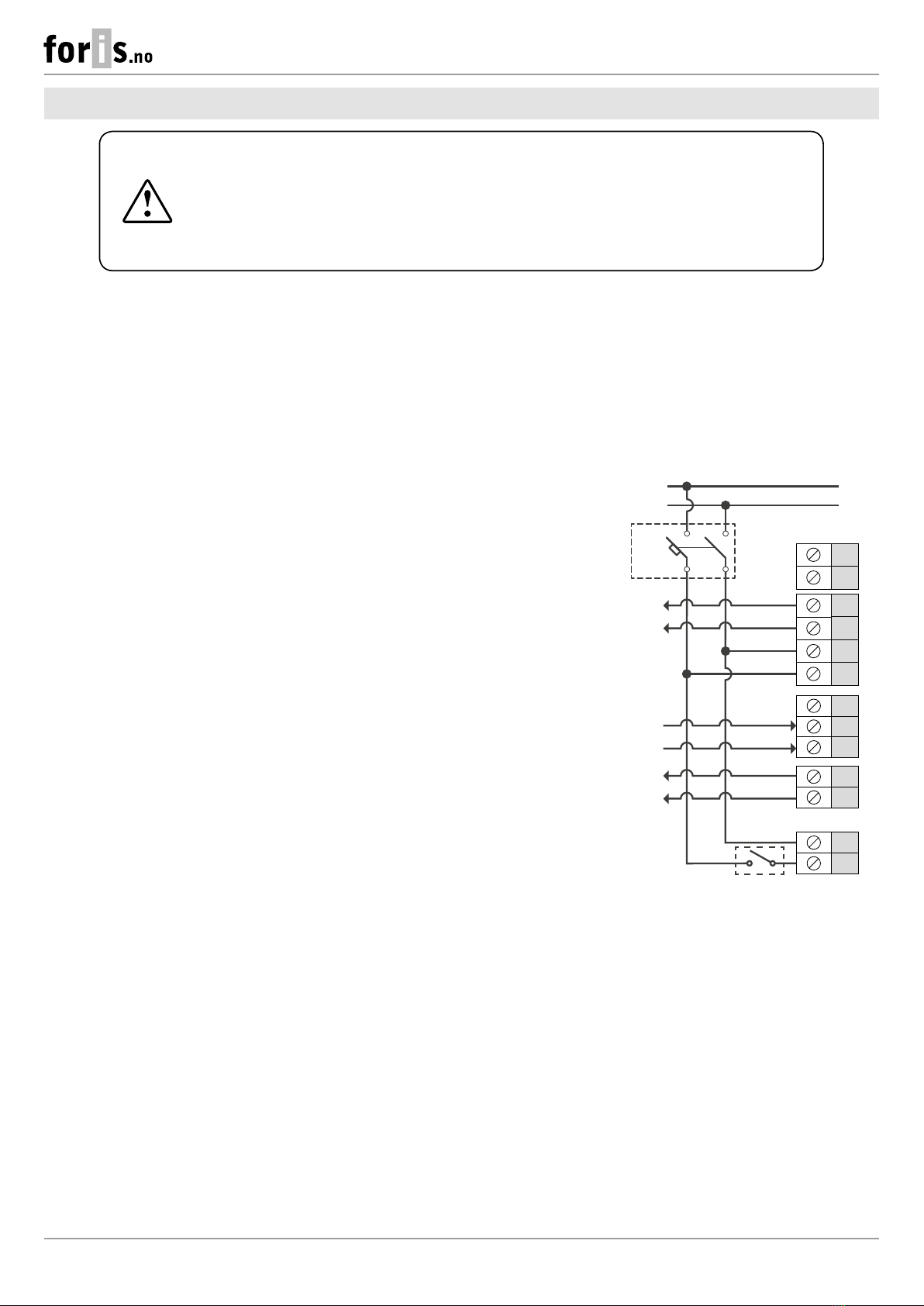
External connections diagram
The ventilator design enables connecting any external controls
with a normally opened contact (NO-contact), such as an external
CO₂ sensor, humidity sensor, relay switch, etc.
When the normally open contact of the external device is closed,
the ventilator goes to a maximum speed.
The ventilators can be connected in series and in parallel with a
central control by the master ventilator.
In case of in series or in parallel connection of several ventilators
power is supplied either from a previous ventilator or from power
mains.
N
L
1a
2a
N
L (~)
N (~)
L
In
Gnd
NO1
NO2
+12V
Gnd
Out
QF*
Control signal output
to the next ventilator
Power
АС 100-240V
50/60 Hz
Power to the
next ventilator
Normally open contact
of the external device
(relay sensor)
Control signal input from
the previous ventilator
CONNECTION TO POWER MAINS
13
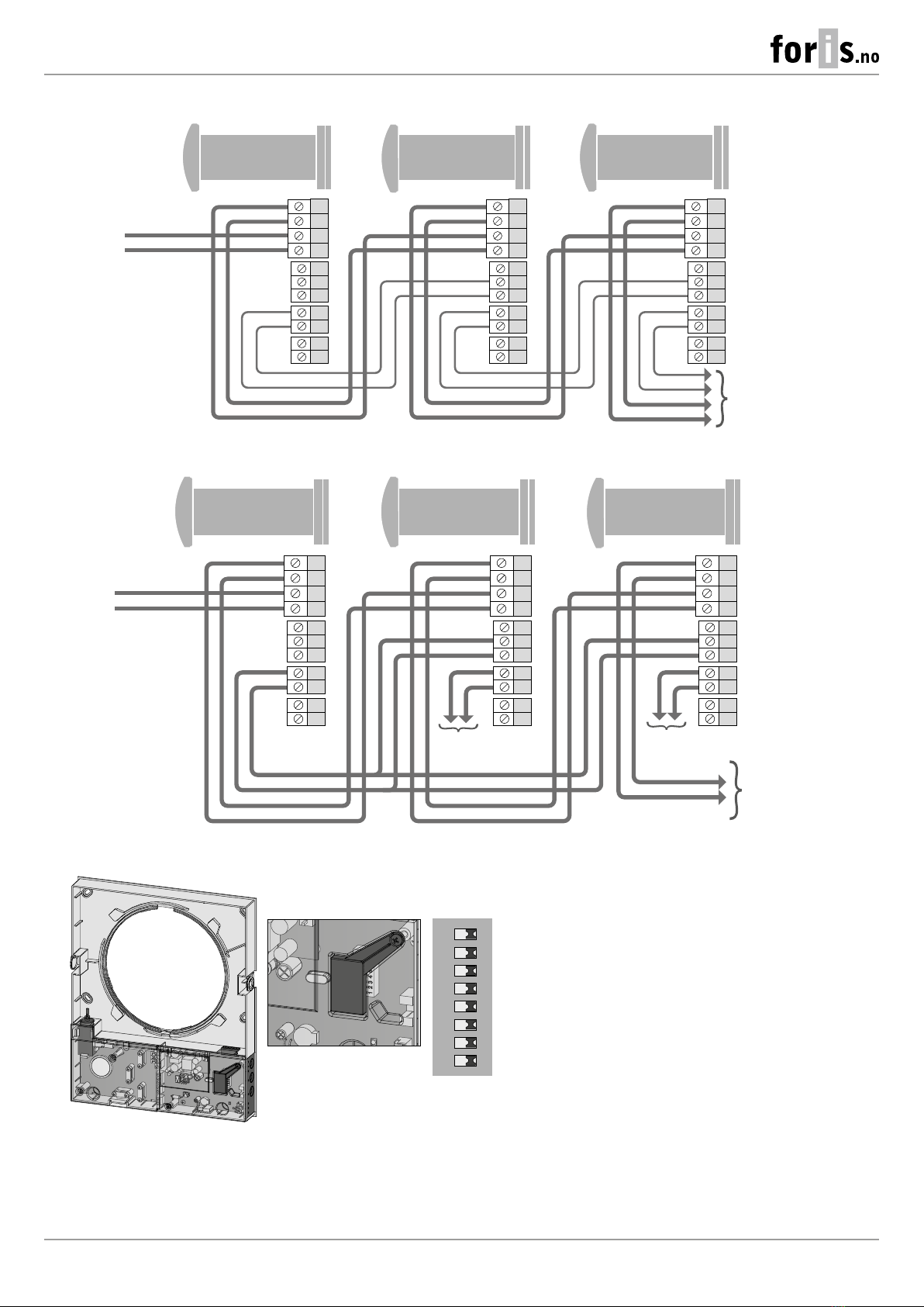
Wiring diagram for in series connection
N
L
N
L
In
Gnd
Gnd
Out
NO1
NO2
+12V
N
L
N
L
In
Gnd
Gnd
Out
NO1
NO2
+12V
N
L
N
L
In
Gnd
Gnd
Out
NO1
NO2
+12V
Master Slave 1 Slave N
N
L
Power input
АС 100-240V 50/60 Hz
to the next
ventilator
Wiring diagram for in parallel connection
Master Slave 1 Slave N
N
L
N
L
In
Gnd
Gnd
Out
NO1
NO2
+12V
N
L
N
L
In
Gnd
Gnd
Out
NO1
NO2
+12V
N
L
N
L
In
Gnd
Gnd
Out
NO1
NO2
+12V
N
L
Power input
АС 100-240 V 50/60 Hz
to the next
ventilator
to the next
ventilator
to the next
ventilator
Ventilator setup
ON DIP
12345678
Open the rubber plug
DIP switch
under the plug
Prior to operating the ventilator set it up using the DIP
switch. It is located on the controller circuit board.
To access the DIP switch, take off the front panel of the
indoor unit and uplift the rubber plug that covers the
switch.
14
TwinFresh Expert RA/M1-50 (C1) V.3
Positioning of the DIP switches
1
Turning the ventilator o is allowed. The switch position enables switching the ventilator off with the button on the side control
panel.
1
Turning the ventilator o is not allowed. The switch position disables switching the ventilator off with the button on the side control
panel.
TwinFresh Expert RA/M1-50 V.3
Fan rotation direction. For controlled ventilation it is recommended to install the ventilators pairwise and integrate them in a group using a signal
cable. Set one half of the connected units into supply mode and the other half into extract mode.
2
In the Ventilation mode the ventilator supplies air to the room.
In the Regeneration mode the ventilator starts operating first in the air supply mode.
2
In the Ventilation mode the ventilator extracts the air from the room.
In the Regeneration mode the ventilator starts operating first in the air exhaust mode.
Humidity sensor set value. The humidity sensor measures the extract air humidity. If the extract air humidity is above the set point, the ventilator
switches to Speed III. As humidity drops down to the set point, the ventilator changes to pre-set speed after elapsing of the time set on the turn-on
delay timer.
Humidity control is
disabled
Set value 40 % Set value 50 % Set value 60 % Set value 70 % Set value 80 %
345
345
345
345
345
345
Delay timer. During activation of the humidity sensor or any other external device the ventilator switches to higher speed. After normalization of the
indoor humidity level or any other air parameters the ventilator will switch to the previous mode after the set time.
Time delay 0 min Time delay 5 min Time delay 15 min Time delay 30 min
6 7
6 7
6 7
6 7
Resetting timer lter
8
To reset the filter timer, turn on the DIP switch for a period of at least 3 seconds and then turn it off.
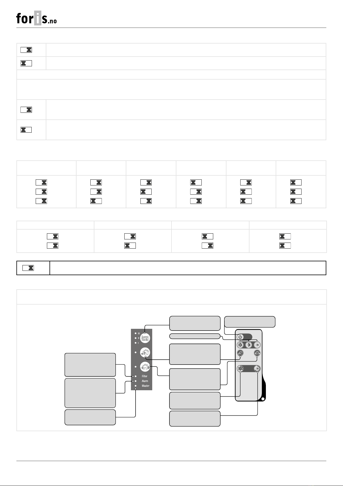
Ventilator control
The ventilator can be operated with the remote control or the control buttons on the side part of the indoor unit, as figured below.
In case of in series or in parallel connection, the signal from a control unit is received by the first ventilator (Master) only.
Turning
the ventilator on/o
Party mode
Activation of Speed III by timer
(4 hours by default).
Night mode
Activation of Speed I by timer
(8 hours by default).
Speed selection
Speed/Standby
The speed selection sequence is as
follows: I-II-III-Standby
Regeneration mode
In this mode the unit switches
between the supply and the
extraction modes every 70 seconds
with heat recovery. Heat recovery is
performed in this mode.
Ventilation mode
The ventilator operates in the supply
or extraction mode at a set speed.
Remote control
Buttons on the
ventilator casing
Alarm indicator
In case of the motor jam, the Alarm
indicator starts glowing and the
ventilator stops. All the ventilators
connected in series stop
synchronously.
Master indicator
Indicator of the first ventilator in the
group.
Filter indicator
After the set filter replacement
periodicity (90 days) has expired, the
Filter indicator starts glowing. In this
case, clean or replace the filters.

15
Ventilator control with the buttons on the indoor unit
The speed selection sequence is as follows: I-II-III-Standby. All the units integrated in a single network operate according to the speed
settings of the Master unit.
I: permanent indicator glowing indicates operation of the unit at Speed I. The indicator blinks when the first speed timer is activated.
Iand II: permanent glowing of these indicators indicates operation of the unit at Speed II.
I, II and III: permanent glowing of these indicators indicates operation of the ventilation unit at Speed III. Blinking of the indicators I, II and
III indicates activation of the timer for Party mode or the turn-off delay timer triggered by any connected external sensors or the integrated
humidity sensor.
Regeneration mode:
TwinFresh Expert RA/M1-50 V.3
The rotation direction of both fans changes to opposite every 70 seconds. Heat recovery is performed in this mode.
Ventilation mode:
TwinFresh Expert RA/M1-50 V.3
The ventilator operates in the supply or extraction mode at a set speed. The air flow direction depends on positioning of the DIP switch
(set to air extract by default).
Filter
Contamination indicator of lters. 90 days (continuous operation) after installation of the cartridge the Filter contamination indicator
starts glowing. In this case, clean or replace the filters (see section Technical maintenance).
During in-series connection the Master ventilator indicator has a steady glow and the indicator of the ventilator requiring filter replacement
blinks. To reset the filter timer of the units, switch the DIP switch no. 8 on for at least 3 seconds and then turn it off.
Alarm
Alarm indicator for emergency shutdown of the unit. Permanent glowing of the Alarm indicator of the Master unit indicates an alarm in
the network of the connected ventilation units. Its blinking indicates shutdown of a specific ventilation unit in the network.
In case of an emergency shutdown of the TwinFresh Expert RA/M1-50 V.3 unit in the network, the defective ventilation unit is marked with
the blinking Alarm indicator. All the connected TwinFresh Expert RA/M1-50 V.3 ventilation units are also stopped.
Master
Master unit indicator. Permanent glowing of the indicator shows the leading unit in the network (Master unit). Indicator blinking indicates
the driven unit (Slave unit) and no connection to the Master unit.
No glowing of the lamp indicator means that this ventilation unit is a Slave ventilation unit and it is connected to a Master unit.
Remote control of the ventilator
Turning the ventilator on/off. The unit may be turned off only if it is enabled by the settings.
Reset of alarm and timer settings.
Ventilator speed selection: Speed III-II-I respectively.
Regeneration mode
In this mode, for the TwinFresh Expert RA/M1-50 V.3 ventilators, the direction of fan rotation changes every 70 seconds.
Heat regeneration is performed in this mode.
Ventilation mode
In this mode, the TwinFresh Expert RA/M1-50 V.3 ventilators supply or extract air at the selected speed. The air flow direction
depends on positioning of the DIP-switch (set to air extract by default).
Timer buttons:
Party mode: 4 hours on the third speed Night ode: 8 hours on the first speed
Upon expiration of the set time period the ventilator reverts to a pre-set speed.
Press any button of the manual speed setting to deactivate the timer.

16
TwinFresh Expert RA/M1-50 (C1) V.3
Air ow cut-o
Press the front panel to close the air duct. The fan turns off automatically. The unit functionality is not changed.
To open the air duct, pull the front panel while holding the special recesses. The fan starts operating according to the actual speed
setting.
Air duct shut-off Air duct
opening
The front panel incorporates an operating LED indicator. During the dark time the indicator light intensity drops down.

17
TECHNICAL MAINTENANCE
Maintenance of the ventilator means regular cleaning of the ventilator surfaces of dust and cleaning and/or replacement of the filters.
After the set filter replacement periodicity (90 days) has expired the Filter indicator starts glowing. Before performing maintenance,
stop the ventilator using the remote control or the buttons on the indoor unit, then disconnect it from power mains using the circuit
breaker. Afterwards, carry out the following steps:
1. Press the latches on the side of the indoor control unit to take off the front part.
Please make sure the shutter actuator rod is in lower position during re-installation of the front panel. If the rod is up, please
wait for about 2 minutes until it goes down.
2. Disconnect the connector from the circuit board. Do not remove the connector by pulling the wires. Use a flat screwdriver to uplift
it if required.
Disconnect the connector
from the circuit board.
Do not pull on
the electric cable! Use a flat screwdriver to
disconnect the connector.
3. Pull the cord to remove the cartridge from the air duct. Clean the filters as often as required, but at least 3 times a year.
When installing the front
panel, the shutter actuator rod
of the TwinFresh Expert RA1
model must be lowered
.

18
TwinFresh Expert RA/M1-50 (C1) V.3
4. Wash the filters and let those dry out completely. Install the dry filters in their place and assemble the unit in the reverse order. Vacuum
cleaning is allowed.
The filter rated service life is 3 years. For new filters contact the Seller.
Some dust may accumulate on the heat exchanger block even in
case of regular maintenance of the filters.
To maintain high heat recovery efficiency, the regenerator should
be cleaned regularly with a vacuum cleaner at least once a year.
To reset the filter timer, before installing the front part of the indoor unit back in place, supply power to the ventilator using the circuit
breaker, then switch on the DIP switch no. 8 for at least 3 seconds and switch it off.
If necessary, the battery in the remote control can be replaced.
After long-term usage of the remote control the battery must be
replaced.
No response of the unit for pressing the remote control buttons
indicates the need to replace the battery.
The battery type is CR2025.
Remove the holder with the battery from the lower part of the
remote control.
Replace the battery and install the holder with a new battery back
to the remote control.
+
CR2025
3V
+
CR2025
3V

19
Possible reasons and troubleshooting
Problem Possible reasons Troubleshooting
When switching on the
ventilator, the fan does not
start.
No power supply.
Make sure the power supply line is connected
correctly, otherwise troubleshoot the connection
error.
The motor is jammed, the impeller blades are
soiled.
Turn the ventilator off. Troubleshoot the motor jam
and impeller clogging. Clean the blades. Restart the
ventilator.
Circuit breaker tripping during
the ventilation unit start-up.
Overcurrent as a result of short circuit in the
electric line.
Turn the ventilator off.
Contact the Seller for further information.
Low air flow.
Low set fan speed. Set higher speed.
The filters, the fan or the regenerator are clogged. Clean or replace the filter. Clean the fan and the
heat exchanger.
Noise, vibration.
The impeller is clogged. Clean the impeller.
Loose screw connection of the unit casing or the
outer ventilation hood.
Tighten the screws of the ventilator or the outer
ventilation hood.
TROUBLESHOOTING
STORAGE AND TRANSPORTATION REGULATIONS
• Store the unit in the manufacturer’s original packaging box in a dry closed ventilated premise with temperature range
from +5 °C to +40 °C and relative humidity up to 70 %.
• Storage environment must not contain aggressive vapors and chemical mixtures provoking corrosion, insulation, and sealing
deformation.
• Use suitable hoist machinery for handling and storage operations to prevent possible damage to the unit.
• Follow the handling requirements applicable for the particular type of cargo.
• The unit can be carried in the original packaging by any mode of transport provided proper protection against precipitation and
mechanical damage. The unit must be transported only in the working position.
• Avoid sharp blows, scratches, or rough handling during loading and unloading.
• Prior to the initial power-up after transportation at low temperatures, allow the unit to warm up at operating temperature for at least
3-4 hours.

20
TwinFresh Expert RA/M1-50 (C1) V.3
MANUFACTURER’S WARRANTY
The product is in compliance with EU norms and standards on low voltage guidelines and electromagnetic compatibility. We hereby
declare that the product complies with the provisions of Electromagnetic Compatibility (EMC) Directive 2014/30/EU of the European
Parliament and of the Council, Low Voltage Directive (LVD) 2014/35/EU of the European Parliament and of the Council and CE-marking
Council Directive 93/68/EEC. This certificate is issued following test carried out on samples of the product referred to above.
The manufacturer hereby warrants normal operation of the unit for 24 months after the retail sale date provided the user's observance
of the transportation, storage, installation, and operation regulations. Should any malfunctions occur in the course of the unit operation
through the Manufacturer's fault during the guaranteed period of operation, the user is entitled to get all the faults eliminated by the
manufacturer by means of warranty repair at the factory free of charge. The warranty repair includes work specific to elimination of faults
in the unit operation to ensure its intended use by the user within the guaranteed period of operation. The faults are eliminated by means
of replacement or repair of the unit components or a specific part of such unit component.
The warranty repair does not include:
• routine technical maintenance
• unit installation/dismantling
• unit setup
To benefit from warranty repair, the user must provide the unit, the user's manual with the purchase date stamp, and the payment
paperwork certifying the purchase. The unit model must comply with the one stated in the user’s manual. Contact the Seller for warranty
service.
The manufacturer’s warranty does not apply to the following cases:
• User’s failure to submit the unit with the entire delivery package as stated in the user’s manual including submission with missing
component parts previously dismounted by the user.
• Mismatch of the unit model and the brand name with the information stated on the unit packaging and in the user's manual.
• User’s failure to ensure timely technical maintenance of the unit.
• External damage to the unit casing (excluding external modifications as required for installation) and internal components caused
by the user.
• Redesign or engineering changes to the unit.
• Replacement and use of any assemblies, parts and components not approved by the manufacturer.
• Unit misuse.
• Violation of the unit installation regulations by the user.
• Violation of the unit control regulations by the user.
• Unit connection to power mains with a voltage different from the one stated in the user's manual.
• Unit breakdown due to voltage surges in power mains.
• Discretionary repair of the unit by the user.
• Unit repair by any persons without the manufacturer’s authorization.
• Expiration of the unit warranty period.
• Violation of the unit transportation regulations by the user.
• Violation of the unit storage regulations by the user.
• Wrongful actions against the unit committed by third parties.
• Unit breakdown due to circumstances of insuperable force (fire, flood, earthquake, war, hostilities of any kind, blockades).
• Missing seals if provided by the user’s manual.
• Failure to submit the user’s manual with the unit purchase date stamp.
• Missing payment paperwork certifying the unit purchase.
FOLLOWING THE REGULATIONS STIPULATED HEREIN WILL ENSURE A LONG AND
TROUBLEFREE OPERATION OF THE UNIT.
USER’S WARRANTY CLAIMS SHALL BE SUBJECT TO REVIEW ONLY UPON PRESENTATION
OF THE UNIT, THE PAYMENT DOCUMENT AND THE USER’S MANUAL WITH THE
PURCHASE DATE STAMP.
This manual suits for next models
2
Table of contents
Other foris Fan manuals

Popular Fan manuals by other brands

Jaga
Jaga OXRE.015 installation instructions

Ruck Ventilatoren
Ruck Ventilatoren ROTO KOMPAKT Assembly and operating manual

Fantech
Fantech ERV-WI 500 Installation, operation and maintenance manual
Beacon
Beacon LUCCI AIRFUSION HAVANA installation instructions

ACB
ACB Vento BORA instructions

Panasonic
Panasonic FV-24JR2 Installation and operationg instructions


