foris TwinFresh Expert RW1-50 User manual
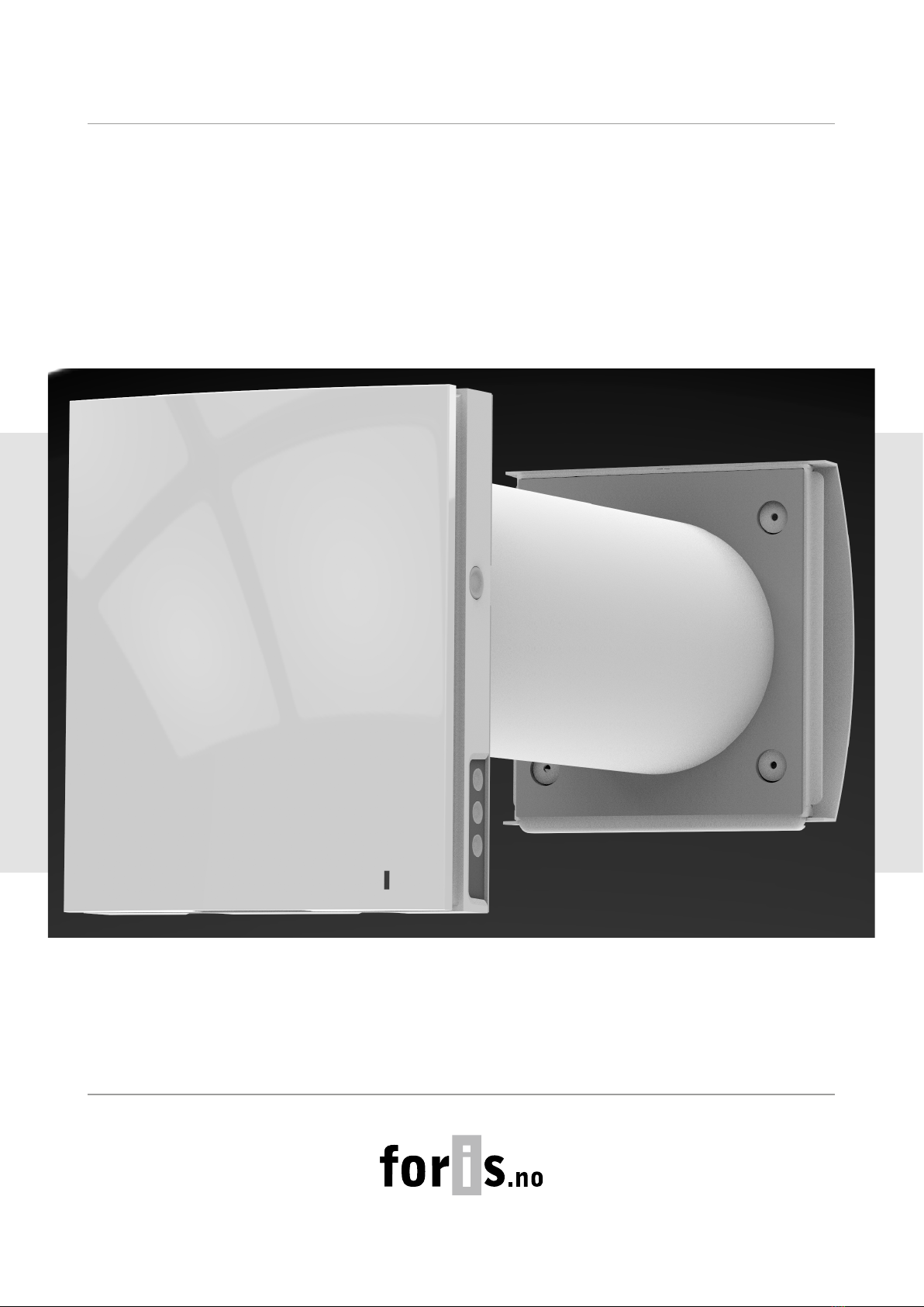
TwinFresh Expert RW1-50 V.3
Single-room reversible energy recovery ventilator
USER’S MANUAL

2
TwinFresh Expert RW1-50 V.3
CONTENTS
This user’s manual is a main operating document intended for technical, maintenance, and operating staff.
The manual contains information about purpose, technical details, operating principle, design, and installation of the
TwinFresh Expert RW1-50 V.3 unit and all its modifications.
Technical and maintenance staff must have theoretical and practical training in the field of ventilation systems and should be able to
work in accordance with workplace safety rules as well as construction norms and standards applicable in the territory of the country.
Safety requirements..................................................................................................................................................................... 2
Purpose................................................................................................................................................................................................ 4
Delivery set........................................................................................................................................................................................ 4
Designation key.............................................................................................................................................................................. 4
Technical data.................................................................................................................................................................................. 5
Design and operating principle ........................................................................................................................................... 6
Mounting and set-up.................................................................................................................................................................. 8
Connection to power mains .................................................................................................................................................. 11
Technical maintenance.............................................................................................................................................................. 24
Storage and transportation regulations.......................................................................................................................... 26
Manufacturer’s warranty........................................................................................................................................................... 27
Certificate of acceptance.......................................................................................................................................................... 31
Seller information.......................................................................................................................................................................... 31
Installation certificate.................................................................................................................................................................. 31
Warranty card................................................................................................................................................................................... 31
All user’s manual requirements as well as the provisions of all the applicable local and national
construction, electrical, and technical norms and standards must be observed when installing
and operating the unit.
Disconnect the unit from the power supply prior to any connection, servicing, maintenance, and
repair operations.
Only qualied electricians with a work permit for electrical units up to 1000 V are
allowed for installation. The present user’s manual should be carefully read before
beginning works.
Check the unit for any visible damage of the impeller, the casing, and the grille before starting
installation. The casing internals must be free of any foreign objects that can damage the
impeller blades.
While mounting the unit, avoid compression of the casing! Deformation of the casing may result
in motor jam and excessive noise.
Misuse of the unit and any unauthorised modifications are not allowed.
Do not expose the unit to adverse atmospheric agents (rain, sun, etc.).
Transported air must not contain any dust or other solid impurities, sticky substances, or fibrous
materials.
Do not use the unit in a hazardous or explosive environment containing spirits, gasoline,
insecticides, etc.
SAFETY REQUIREMENTS

3
TwinFresh Expert RW1-50 V.3
Do not close or block the intake or extract vents in order to ensure the efficient air flow.
Do not sit on the unit and do not put objects on it.
The information in this user’s manual was correct at the time of the document’s preparation.
The Company reserves the right to modify the technical characteristics, design, or configuration
of its products at any time in order to incorporate the latest technological developments.
Never touch the unit with wet or damp hands.
Never touch the unit when barefoot.
THE PRODUCT MUST BE DISPOSED SEPARATELY AT THE END OF ITS SERVICE LIFE.
DO NOT DISPOSE THE UNIT AS UNSORTED DOMESTIC WASTE.
This unit is not intended for use by persons (including children) with reduced physical, sensory
or mental capabilities, or lack of experience and knowledge, unless they have been given
supervision or instruction concerning use of the unit by a person responsible for their safety.
Children should be supervised to ensure that they do not play with the unit.
Connection to the mains must be made through a disconnecting device, which is integrated
into the fixed wiring system in accordance with the wiring rules for design of electrical units,
and has a contact separation in all poles that allows for full disconnection under overvoltage
category III conditions.
If the supply cord is damaged, it must be replaced by the manufacturer, its service agent, or
similarly qualified persons in order to avoid a safety hazard.
Ensure that the unit is switched off from the supply mains before removing the guard.
Precautions must be taken to avoid the back-flow of gases into the room from the open flue of
gas or other fuel-burning appliances.
4
TwinFresh Expert RW1-50 V.3
PURPOSE
The ventilator is designed to ensure continuous mechanical air exchange in flats, cottages, hotels, cafés and other domestic and public
premises. The ventilator is equipped with a regenerator that enables supply of fresh filtered air heated by means of extract air heat energy
recovery.
The ventilator is designed for installation on external walls.
The unit is rated for continuous operation.
Name Number
Indoor assembly unit of the ventilator 1 pc.
Air duct 1 pc.
Sound-absorbing material 1 pc.
Fan assembly 1 pc.
Heat exchanger assembly 1 pc.
Outer ventilation hood 1 pc.
Remote control 1 pc.
Cardboard mounting plate 1 pc.
Mounting kit 2 packages
Foam wedges 1 kit
User’s manual 1 pc.
Mounting hood installation instruction 1 pc.
Packing box 1 pc.
DELIVERY SET
DESIGNATION KEY
TwinFresh Expert RW1 -50 L-2 V.3
Unit version
Ventilation hood model
Air duct length
_ – 500 mm
L – 700 mm
L035 – 350 mm
L10 – 1000 mm
Rated air ow [m/h]
Ventilator series
Series of reversible ventilators with unidirectional air flow

5
TwinFresh Expert RW1-50 V.3
A
370 mm
Air duct length
Wall thickness
Outer ventilation
hood
Indoor unit
Heat recovery unit
Fan unit
Sound absorbing
material
Layout of the ventilator units inside the wall
68
235
285
207
85
137
138
The temperature in the room where the indoor unit of the ventilator is installed must be in the range from +1 ˚C to +40 ˚C with relative air
humidity up to 65 % (no condensation buildup). A short-term increase in the humidity level up to 80% is permissible, while condensate
may form on the surface of the unit.
If the conditions of use of the ventilator are outside the specified limits, turn off the ventilator. Provide fresh air with open windows.
The temperature of the transported air should be in the range from -20 ˚C to +40 ˚C.
The unit is rated as a class II electric appliance.
Ingress protection rating against access to hazardous parts and water ingress is IP24.
The ventilator design is constantly being improved, thus some models may be slightly different from those described in this manual.
Technical specifications of the particular model are indicated on the unit casing.
A – protruding part of the air duct on the outer wall. Depends on the selected ventilation hood type.
The supplied air duct length and the supplied ventilation hood model depends on the ventilator model, refer to the Designation Key
section.
The overall and connecting dimensions of the outer ventilation hood, the outside protrusion length of the air duct Aand the mounting
sequence of the hood are stated in its installation instruction.
The overall dimensions of the front panel are stated below.
TECHNICAL DATA
Wi-Fi technical data
Standard IEFE 802,11, b/g/n
Frequency band [GHz] 2.4
Transmission power [mW] (dBm) 100(+20)
Network DHCP
WLAN safety WPA, WPA2

6
TwinFresh Expert RW1-50 V.3
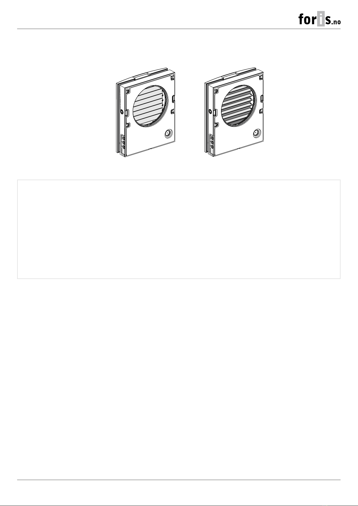
Front part of the indoor unit with a face panel
Press down on the front panel to close the air duct tightly. To open the air duct, pull the
front panel towards you using the grooves in the top and bottom of the panel.
Fulfils the decorative function.
Back part of the indoor unit
The assembly unit includes a control board and basic control units located on the
side of the indoor unit.
The design enables to shut off the air duct in case of an extended downtime of the
ventilator.
Air duct
Plastic air duct.
Outer ventilation hood
Prevents ingress of water and foreign objects into the ventilator.
Each ventilator model has a matching ventilation hood model.
Fan unit
Creates air flow.
Regenerator unit
Provides heat recovery.
Sound-absorbing material
A layer of sound-absorbing material for attenuation
of noise generated during the ventilator operation.
The ventilator consists of an indoor unit with a decorative front panel, a fan unit, a regenerator unit, an air duct with a sound absorbing
layer and an outer ventilation hood.
The fan and regenerator units consist of two filters that ensure rough air filtration and prevent ingress of dust and foreign objects into
the regenerator and the fan.
The indoor unit is equipped with automatic shutters that close during the ventilator standstill and prevent air backdraft.
The outer ventilation hood is used to prevent direct ingress of water and other objects to the ventilator.
DESIGN AND OPERATING PRINCIPLE
Technical specifications of the particular model are indicated on the unit casing.
7
TwinFresh Expert RW1-50 V.3
The shutters are closed The shutters are open
OPERATING LOGIC OF THE AUTOMATIC SHUTTERS
The indoor unit of the ventilators is equipped with automatic shutters. During the ventilator operation the automatic shutters are opened
and let the air flow freely through the ventilator. The automatic shutters are closed for 2 minutes at the ventilator shut down.
VENTILATOR OPERATION MODES
Ventilation: the ventilator runs either in the air exhaust or air supply mode at a set speed.
In this mode some of the ventilators in the network run in the air supply mode and the other ones in air exhaust mode, depending on
the position of the DIP switch No. 3 (See section DIP switch positions).
Boost: the ventilator goes to the maximum speed without changing the operation mode.
Regeneration: the ventilator runs in two cycles, 70 seconds each, with heat and humidity regeneration.
• Cycle I. Warm stale air is extracted from the room and flows through the ceramic regenerator, which gradually absorbs heat and
humidity. In 70 seconds, as the ceramic regenerator gets warmed, the ventilator is switched to supply mode.
• Cycle II. Fresh intake air from outside flows through the ceramic regenerator, absorbs accumulated moisture and is heated by
the heat stored in the regenerator. In 70 seconds, as the ceramic regenerator gets cooled down, the ventilator is switched to air
extraction mode and the cycle is renewed. If two ventilators are installed, they operate with opposite rotation directions in this
mode. While one ventilator supplies air, the other one extracts it.
Air supply: the ventilator operates in the air supply mode irrespective of the position of the DIP switch No. 3 (see section DIP switch
positions).
8
TwinFresh Expert RW1-50 V.3
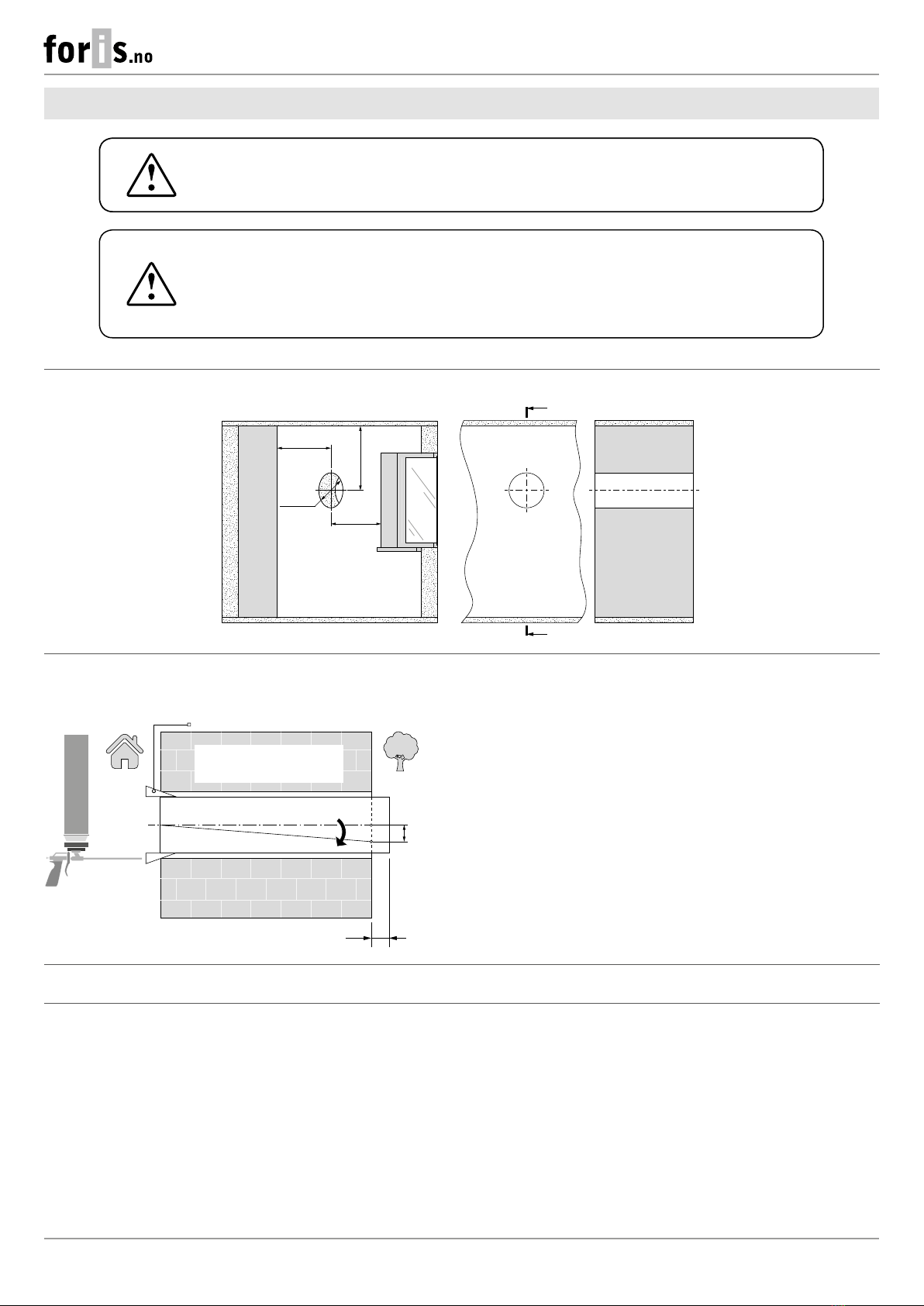
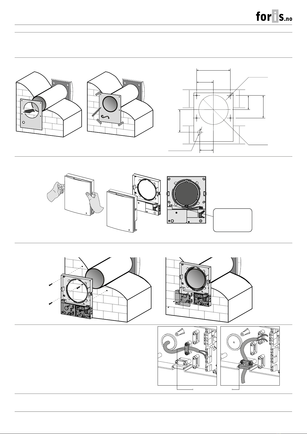
1. Prepare a round core hole in the outer wall. The hole size is shown in the figure below.
A
AA-A
ø 250
min 300
min 300
min 300
2. Insert the air duct in the wall. For ease of installation use the foam wedges included in the delivery set. The air duct end must protrude
for the distance A that enables installation of the outer ventilation hood. The distance A is stated in the installation instruction for the
ventilation hood.
A
Fill the gaps between the wall
and the hole with a mounting
foam.
Mounting wedge
Install the air duct with the minimum slope of 3 mm downwards
from the outer wall side.
The air duct can be cut by calculating preliminary the required length
or after fixing the air duct on the wall (in this case, it is necessary to
have access to the outside part of the wall).
3. Install the outer ventilation hood. The mounting sequence of the outer ventilation hood is described in the installation instruction for
the ventilation hood.
DO NOT BLOCK THE AIR DUCT OF THE INSTALLED VENTILATOR WITH DUST
ACCUMULATING MATERIALS, SUCH AS CURTAINS, CLOTH SHUTTERS, ETC.
AS IT PREVENTS AIR CIRCULATION IN THE ROOM.
READ THE USER'S MANUAL BEFORE INSTALLING THE UNIT.
MOUNTING AND SETUP
9
TwinFresh Expert RW1-50 V.3
4. Stick the delivered cardboard master plate on the indoor wall using a mounting tape. The large opening in the master plate must be
axially aligned with the air duct. For aligning the master plate with respect to the horizon line it is recommended to use a builder’s level.
Then mark the fastening holes for installation of the supplied dowels and drill the holes to a required depth.
Route the power cable of the ventilator from the wall through the marked opening on the template.
Hole marking for fan fastening
207
Ø 5
Ø 160
87.5 138
103.5
137
85
Ø 23
4 holes
5. Unlatch and detach the front part of the indoor unit from its back part.
WARNING!
Do not put on the front panel
until the thermal actuator rod
is completely lowered.
Blinking of the white LED
indicates that the
THERMAL ACTUATOR IS NOT LOWERED
6. Fix the back part of the indoor unit on the wall with the screws supplied with the mounting kit of the ventilator. Remove the two
retaining screws from the left transparent cover to enable access to the terminals.
7. Route the power cable as figured below and connect the
ventilator to power mains in compliance with the external wiring
diagram, see section Connection to power mains.
Fix the power cable and the signal cables with a cable clamp.
After completion of the electrical connection re-install the
transparent cover in site.
Cable clamp

10
TwinFresh Expert RW1-50 V.3
8. Install the fan unit and the regenerator unit into the air duct as figured below. Then fix the wire with the retaining clip and connect the
connector to the control board.
Insert the sound-absorbing material into the air duct. Roll the layer of the sound absorbing material to match the air duct diameter. Insert
the sound absorbing roll against stop. Cut off the excess part of the sound-absorbing material.
Insert the ready sound absorbing roll into the air duct.
Lay the cables under the clamp
and connect the socket
connector to the control board.
If the wall thickness is less than that in the layout of the blocks inside the wall from the Technical Data section, you can unfasten the fine
filter holder and assemble the ventilator without it and without sound-absorbing material, as shown in the figure below.
A
307 mm
Air duct length
Wall thickness
Outer ventilation
hood
Indoor unit
Heat recovery unit
Ventilation unit
Layout of the ventilator units inside the wall
with a minimum wall thickness
With this type of installation, the recovery efficiency may decrease and the immission of street noise into the room may increase. This will
also increase the noise level of the ventilator itself.
9. Install the front part of the indoor unit.
11
TwinFresh Expert RW1-50 V.3
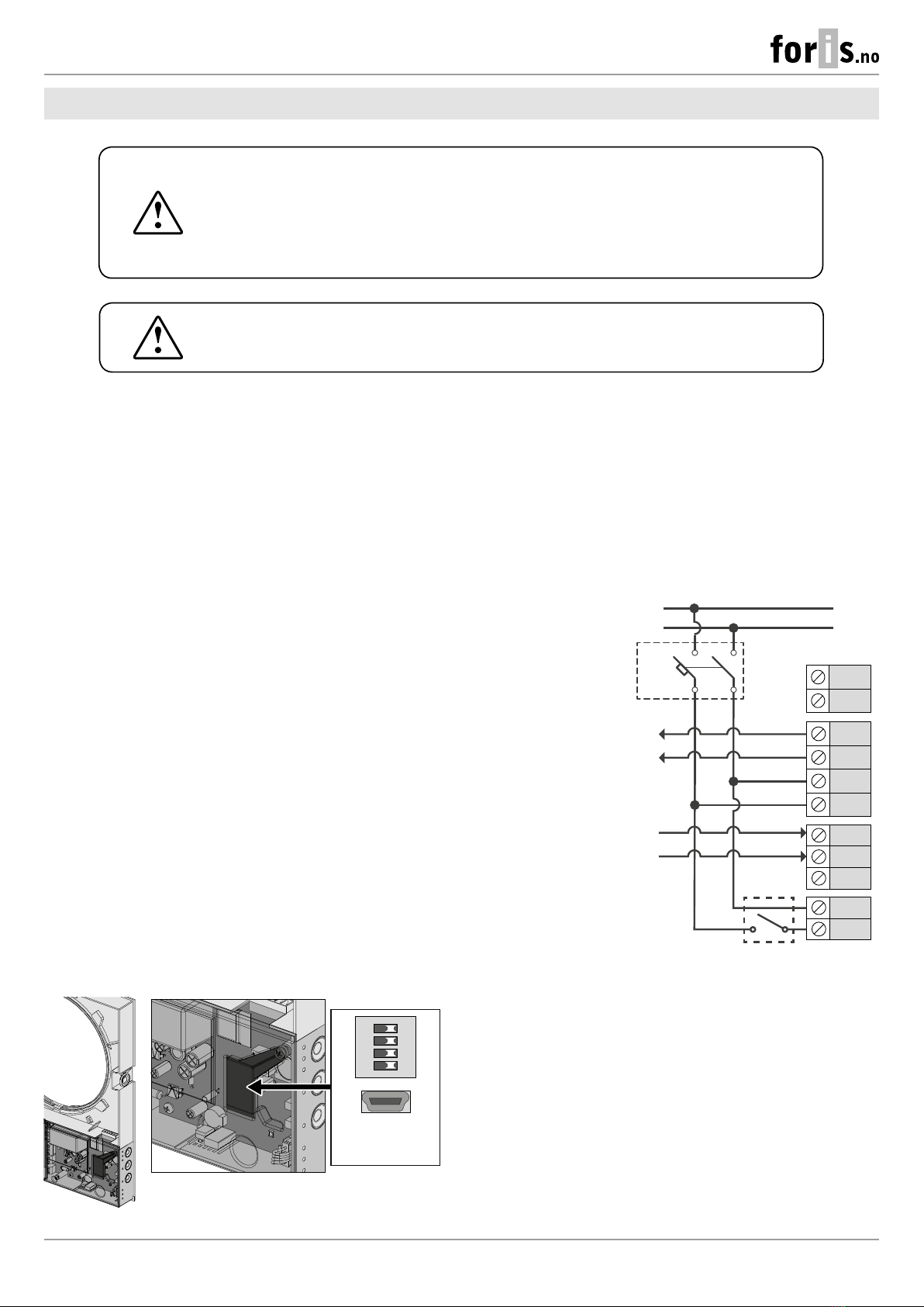
ANY TAMPERING WITH THE INTERNAL CONNECTIONS IS PROHIBITED
AND WILL VOID THE WARRANTY.
The ventilator is rated for connection to single-phase AC 100-240 V 50/60 Hz power mains.
The routing of the power and signalling cables is shown in the “Mounting and set-up” section.
For electric installations use insulated, durable and heat-resistant conductors (cables, wires) with the minimum cross section of 0.5 up to
0.75 mmfor a power cable and 0.25 mmfor signal cables. The cable cross-section is given for reference only. The actual conductor cross-
section selection must be based on its type, maximum permissible heating, insulation, length and installation method.
Use copper wires for all the electric connections!
Connect the unit to power mains via the terminal block installed in the control board in compliance with the wiring diagram and terminal
designation.
N
L
N
L (~)
N (~)
L
i1
Gnd
NO1
NO2
+12V
QF* 1a
2a
Power supply to
the next ventilator
Input for 0-10 V
analogue sensor
NO contact of the
external device
(relay sensor)
Power supply
AC 100-240 V
50/60 Hz
ON DIP
1 2 3 4
DIP switch and USB
connector under
the cover
EXTERNAL CONNECTIONS DIAGRAM
VENTILATOR SETUP
Prior to operating the ventilator set it up using the DIP switch. It is
located on the controller board.
To access the DIP switch, take off the front panel of the indoor unit
and uplift the rubber plug that covers the switch.
Connect the unit to power mains through the external automatic switch with a
magnetic trip integrated into the fixed wiring system. The tripping current of the
circuit breaker is selected based on the electrical characteristics shown on the
label of the ventilator casing.
The ventilator design enables connecting any external controls with a normally
opened contact (NO contact), such as an external COsensor, a humidity sensor,
a switch, etc.
When the NO contact of the external device is closed, the unit changes to the
maximum speed.
An analogue sensor with output voltage 0-10 V is also compatible with the unit.
POWER OFF THE POWER SUPPLY PRIOR TO ANY OPERATIONS WITH THE UNIT.
THE UNIT MUST BE CONNECTED TO POWER SUPPLY BY A QUALIFIED ELECTRICIAN.
THE RATED ELECTRICAL PARAMETERS OF THE UNIT ARE GIVEN ON THE
MANUFACTURER’S LABEL.
CONNECTION TO POWER MAINS
12
TwinFresh Expert RW1-50 V.3
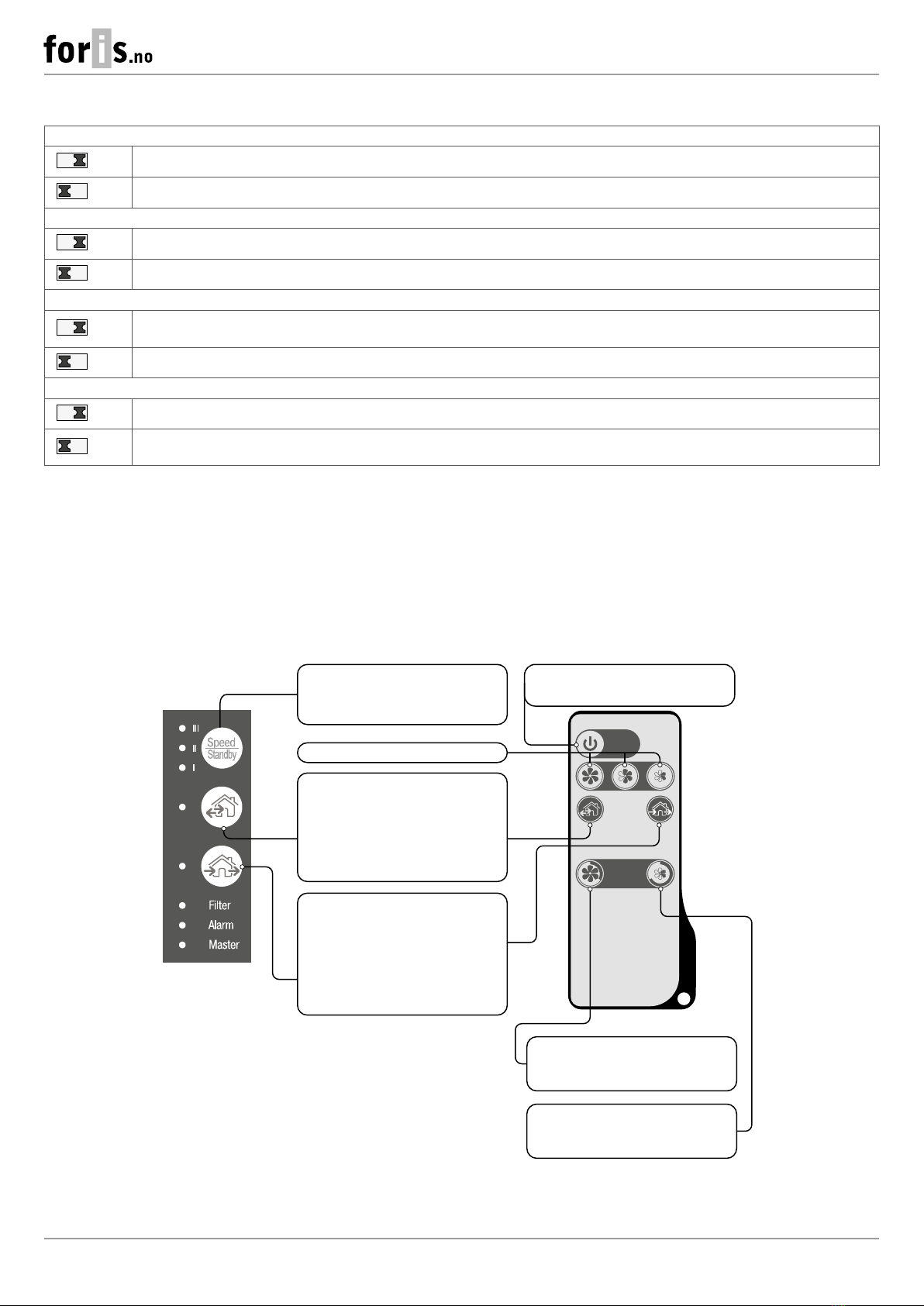
VENTILATOR CONTROL
The ventilation unit may be operated with the following controls:
• infra-red remote control
• control buttons located on the side of the indoor unit (see the figure below)
• Vents TwinFresh V.2 application from a mobile device (smartphone or tablet)
Turning ventilator on/off
Speed selection
Speed/Standby
The speed selection sequence
is follows: I-II-III-Standby
Regeneration mode
The fan rotation direction changes
to opposite every 70 seconds.
Heat recovery is performed
in this mode.
Ventilation mode
The ventilator operates in the supply
or extraction mode at a set speed.
Party mode. Activation of Speed III
by timer (4 hours by default).
Night mode. Activation of Speed I
by timer (8 hours by default).
DIP SWITCH POSITIONS
Ventilator network setup
1
OFF – master unit (hereinafter referred to as “Master unit”)
1
ON – slave unit (hereinafter referred to as“Slave unit”)
Standby mode setup
2
OFF – the ventilator is switched off in the Standby mode.
2
ON – the ventilator operates at Speed I in the Standby mode.
Setup of air flow direction in the Ventilation mode with running ventilators
3
OFF – operation in the exhaust mode.
3
ON – operation in the supply mode.
Restore factory default settings
4
OFF – standard operation of the unit.
4
ON – restore factory default settings. To do this, when the ventilator is running, turn the switch to the ON position, after the sound
signal, turn the switch to the OFF position.

13
TwinFresh Expert RW1-50 V.3
VENTILATOR CONTROL WITH THE BUTTONS ON THE INDOOR UNIT
The speed selection sequence is follows: I-II-III-Standby. All the units integrated in a single network operate
according to the speed settings of the Master unit.
I: permanent indicator glowing indicates operation of the unit at Speed I. Indicator blinking indicates activation
of the Night mode timer.
Iand II: permanent glowing of the indicators I and II indicates operation of the unit at Speed II.
I, II and III: permanent glowing of the indicators I, II and III indicates operation of the ventilation unit at Speed III.
Synchronous blinking of the indicators I, II and III indicates activation of the timer in Party mode or the turn-off
delay timer in the Boost mode in case of actuation of the connected external sensors or the integrated humidity
sensor.
Alternate blinking of the indicators I, II and III indicates that the ventilator runs at the speed set with the mobile
application using the slider selector for manual speed setting or that the Weekly Schedule mode is activated.
Regeneration mode
The rotation direction of both fans changes to opposite every 70 seconds. Heat recovery is performed in this
mode. To enable reverse phase operation of the ventilators, change the position of the DIP switch No. 3.
Ventilation mode
The ventilator operates in the supply or extraction mode at a set speed. The fan rotation direction depends on the
position of the DIP switch No. 3.
No glowing of the indicators “Regeneration” and “Ventilation” indicates forced operation of the ventilation unit in the air supply
mode. This mode may be activated only via the mobile application.
Filter
90 days after installation of the cartridge the filter replacement indicator starts glowing. In this case, clean or
replace the filters (see section Technical maintenance).
After replacement of the filters reset the timer using the mobile application or by pressing and holding the
button on the Master ventilator indoor unit for 5 seconds until a signal sounds.
Alarm
Alarm indicator. In case of failure, the Alarm indicator on the indoor unit glows or blinks.
Reasons of Alarm blinking:
• Battery charge is below the low level.
• No connection between the Master unit and the router.
• Alarm shutdown of the ventilator.
If several interconnected ventilators are running in the same network, in case of shutdown of one ventilator, all of
the ventilators of this network also stop. The Alarm indicator blinks on the defective ventilator and glows on the
other connected ventilators.
In case of communication loss of the Master unit with the router for longer than 20 seconds, the Master unit
switchestoStandbymode (Alarm indicatorblinking)and the Slave units will signalthat there is no communication
with the Master unit (see the description of the Master indicator). After resuming communication, the Slave units
are automatically synchronised with the Master unit.
Master
Permanent glowing of the indicator shows the leading unit in the network (Master unit).
Indicator blinking indicates the driven unit (Slave unit) and no connection to the Master unit.
No glowing of the lamp indicator means that this ventilation unit is a Slave ventilation unit and it is connected
to a Master unit.
Synchronous blinking of all the indicators on the casing of the ventilator indicates that the Setup mode is enabled.

14
TwinFresh Expert RW1-50 V.3
REMOTE CONTROL OF THE VENTILATOR
ON/Standby. The Standby mode depends on the position of the DIP switch 2 (see section DIP switch positions).
The same button is used to reset alarms (Alarm) and to turn off the timers.
Ventilator speed selection: Speed III-II-I respectively.
Regeneration mode
The rotation direction of both fans changes to opposite every 70 seconds. Heat recovery is performed in this
mode. The fan rotation direction depends on the position of the DIP switch 3.
Ventilation mode
The ventilator operates in the supply or extraction mode at a set speed. The fan rotation direction depends on
the position of the DIP switch No. 3.
Timer control buttons:
Party mode: the timer activates operation of the unit at Speed III for a set time period, 4 hours by default. The
timer setting may be changed during setup of the unit on the mobile device.
Night mode: the timer activates operation of the ventilation unit at Speed I for a set time period, 8 hours
by default. The timer setting may be changed during setup of the unit on mobile device.
The ventilation unit reverts to operation with a previous speed setting upon elapse of the set time period.
Press any speed setting key to deactivate the timer or press the timer control button once again.

15
TwinFresh Expert RW1-50 V.3
VENTILATION UNIT OPERATION WITH THE MOBILE APPLICATION
To enable operation of the unit with a mobile device, install the Vents TwinFresh V.2 application to your mobile device. .
Vents TwinFresh V.2 - App Store Vents TwinFresh V.2 Play Market
Your mobile device must have an operating system matching the following parameters:
• iOS – 8 or later. Compatible with iPhone, iPad, iPod.
• Android – 4 or later.
MOBILE APPLICATION CONNECTION TO THE VENTILATOR
Download the Vents TwinFresh V.2 application and install it on the mobile device.
Following message is displayed when launching an application without connection to the ventilator:
By default, the ventilator operates as a Wi-Fi access point. Connect the mobile device to a Wi-Fi access point (FAN: + 16 characters of the
ID number) indicated on the control board of the ventilator.
Wi-Fi access point password: 11111111.
1 2 4 56 873
Enter the Vents TwinFresh V.2 app and create a new connection by following the steps below:
1. Enter the app menu.
2. Select Connection - Home.
3. If the mobile device is connected to the Wi-Fi access point of the unit without a router, select the Default connection.
4. In case of connection via a router, search for network settings.
5. Find the new connection in the list and highlight its ID.
6. Edit the connection details.
7. If necessary, rename the connection and enter a ventilator password.
By default the ventilator password is 1111 (automatically inserted in the input line).
WARNING!!! At this stage the password for the ventilator cannot be changed.
8. Confirm the updated details.
Once the connection has been established, go to the app menu and choose CONTROL.

16
TwinFresh Expert RW1-50 V.3
DESCRIPTION OF MOBILE APPLICATION CONTROL BUTTONS
ON/Standby. Standby mode depends on the position of DIP-switch # 2
(see section DIP switch positions).
Selection of the preset speed: Speed I, II and III respectively.
Manual speed setup. To activate the scroll bar, check it.
Ventilation
The ventilator operates in the supply or extraction mode at a set speed.
The fan rotation direction depends on the position of the DIP switch
No. 3.
Regeneration mode
The rotation direction of both fans changes to opposite every 70
seconds.
Heat recovery is performed in this mode.
Air supply mode
The ventilation unit operates exclusively in the air supply mode.
Night mode
Activation of Speed I timer without changing the ventilator operation
mode (8 hours by default, adjustable in the
Settings – Timers menu).
Weekly schedule
Activation of the ventilator week-scheduled operation.
Party mode
Activation of the Speed III timer without changing the ventilator
operation mode (4 hours by default, adjustable in the
Settings – Timers menu).
DESCRIPTION OF MOBILE APPLICATION INDICATORS
Current type of connection to the ventilator.
Home connection or connection via a cloud server through Internet respectively.
Speed III activation indicator. It goes on after activation of any sensor.
When this mode is activated, all the other modes are deactivated. Upon elapse of the turn-off delay timer countdown
(30 minutes by default) the ventilation unit reverts to the previous mode. Press Power to deactivate this operation
mode.
Humidity indicator. It glows if the indoor humidity is above the set point.
Indicator of external relay sensor. It glows if the external relay sensor is activated.
Indicator of the external analogue sensor 0-10 V. It indicates exceeding the setpoint on the external sensor.
Alarm indicator. It glows in emergency case and can be of two colours:
Red – lights up in case of emergency shutdown of the ventilator.
Orange – lights up in case if there is no battery or the battery is low.
Filter replacement indicator. To reset the filter timer, go to Menu->Settings->Filter.
When simultaneously activating several operation modes that exclude each other, the ventilator selects the mode according to the
following priority:
1. Night mode timer or Party mode timer.
2. Standby.
3. Boost mode.
4. Weekly schedule.
5. Regular mode.

17
TwinFresh Expert RW1-50 V.3
VENTILATOR PASSWORD CHANGE
To change the ventilator password in the mobile device application, go to
Menu->Connection->Home.
1. Choose the connection and press the Settings button.
2. Enter and confirm the password.
3. Press the Change Password button.
1 2 3
TIMER SETUP
To set the Night mode, Party mode timer and the turn-off delay timer for the Boost mode, go to
Menu – Settings – Timers in the mobile application.
The Night mode timer sets the delay for the ventilator to switch to Speed I after the Night mode
activation (8 hours by default).
The Party timer defines the delay for the ventilator to switch to Speed III after the Party mode
activation (4 hours by default).
The turn-o delay timer for the Boost mode defines the delay time for operation at Speed III after
the actuation of any of the sensors and their return to the standard state.
SENSOR SETUP
To set up sensor operation via the mobile app, go to Menu -> Settings -> Sensors.
Humidity sensor: activation of the humidity sensor. When the indoor humidity exceeds the set point,
the unit switches to Speed III. When the humidity level drops below the threshold value, the Boost
turn-off delay timer is activated. When the timer elapses, the ventilator reverts to the previous speed
setting.
0-10 V sensor: activation of the external analogue sensor 0-10 V. When a 0-10 V control signal value
exceeds the set point, the ventilation unit changes to the maximum speed. When the signal drops
below the threshold value, the Boost turn-off delay timer is activated. When the timer elapses, the
ventilator reverts to the previous speed setting.
Relay sensor: activation of the external relay sensor. When the no-contact of the external relay sensor
is closed, the unit changes to the maximum speed. Upon the opening of the NO-contact the Boost
turn-off delay timer is activated. When the timer elapses, the ventilator reverts to the previous speed
setting.
DATE AND TIME SETUP

18
TwinFresh Expert RW1-50 V.3
To set up the ventilator date and time, go to Settings-> Date and time.
Current time: set the current time.
Current date: set the current date.
WEEKLY SCHEDULE SETUP
To set up the weekly schedule in the mobile app, go to Menu -> Settings -> Schedule.
The weekly schedule can be set by means of 4 time intervals available for each day of the week.
You can select one of the three fan speeds or Standby mode for each time interval.
To get the current settings for the selected day of the week, press the Receive button.
To apply the selected settings for the selected day of the week, press the Apply button.
For weekly schedule proper operation make sure to set the correct date and time.
FILTER TIMER RESET
The ventilator filters must be serviced after every 90 hours of continuous operation. The need to replace
the filters is signalled by the indicator in the upper section of the CONTROL menu. Replace the filter
and reset the filter timer.
To reset the filter timer via the mobile app, go to Menu -> Settings -> Filter. Then press the Reset filter
timer button.
The 90 days are counted on the master ventilator only. The filter replacement indication is replicated on
all the Slave units.
If so, replace the filters on all the ventilators on the network. Upon filter timer reset the filter replacement
warning is disabled on all the connected ventilators.
The filter timer can be reset using the button located on the indoor unit (see section Remote control
of the ventilator).
RESTORE FACTORY DEFAULT SETTINGS
To restore the factory settings via the mobile app, go to Menu -> Settings -> Factory settings. Then
press the Reset to factory settings button.
WARNING!
Resetting the factory settings may result in losing Wi-Fi connection with the device.
WIRELESS CONNECTION OF SEVERAL VENTILATION UNITS

19
TwinFresh Expert RW1-50 V.3
The unit operates in two modes:
Master. The unit acts as a leading unit in the network. All the Slave units and mobile devices are connected to the Master unit via Wi-Fi.
The Master unit is operated by means of a mobile device, the remote control or the touch buttons on the unit casing. The control signal
is automatically transferred to the connected Slave units. In this mode the unit responds to a signal from sensors, as a humidity sensor,
an external digital sensor, an external analogue sensor 0-10V and changes its operation mode respectively.
Slave. The unit acts as a driven unit in the network. The Slave unit responds to a signal from the master ventilator only.
Any other signals from other controls are ignored. In this mode the units ignore any other signals from the sensors. In case of
communication loss with the Master unit above 20 seconds, the unit switches to Standby mode.
Timer operation
The ventilators respond to sensor feedback only in the Master mode.
In case of actuation of any sensors, all the connected ventilators go to maximum speed.
WIFI PARAMETER SETUP
Wi-Fi parameters are only set on Master units. To set up ventilator Wi-Fi parameters via the mobile app
go to Menu -> Connection -> Wi-Fi Setup.
Press the Receive button to display the current Wi-Fi settings.
Select one of the Wi-Fi operation modes:
Access Point: access point mode without a home router.
Select the desired security level for the Access point mode:
• Open – open Wi–Fi network without a password.
• WPA PSK: password-protected. Encryption technology, using the WPA protocol, which does not
guarantee complete security.
• WPA2 PSK: password-protected. The type of data encryption for modern network devices.
• WPA/WPA2 PSK: password-protected (recommended). Combined technology that activates
WPA and WPA2 and at the same time provides maximum compatibility with any of your devices.
Enter your access point password and press the Apply button.
Client – the unit operates on the home router network.
Enter the home router details and the IP address type for the Client mode.
• Enter the name of the Wi-Fi home router access point.
• Enter the password for the Wi-Fi home router access point.
Select IP address type:
DHCP: the IP address is set up automatically upon connection to the home router (recommended).
Static: enables manual entry of the desired IP address, subnet mask and default gateway. These
settings are recommended for expert users only. Select this IP address type at your own risk.
Then press the Apply button.
VENTILATOR WIRELESS CONNECTION DIAGRAMS

20
TwinFresh Expert RW1-50 V.3
Wiring diagram 1
Connection of up to 8 Slave units or mobile devices to the Master
unit with its own wireless access point.
In case of connection of 8 Slave units to the Master unit with its
own wireless access point, a mobile device may not be connected.
Master
with a Wi-Fi access point
Slave No. 1 Slave No. 2 Slave No. N
Mobile device
Wiring diagram 2
The Master units, the Slave units and the mobile devices are connected to a wireless access point of the Wi-Fi router.
In this case, the Master unit can operate with the number (N) of Slave units, limited by the technical characteristics of the router.
Master Slave No. 1 Slave No. N
Mobile device Mobile device
Router
with its wireless access point
If the Wi-Fi router capacity is not enough to connect a required number of the units, you may use an extra wireless access point to
connect the other the unit. Several Master units can optionally be connected to the network for arranging a zone control.
Master Slave No. 1 Slave No. N
Mobile device Mobile device
Router
with its wireless access point
Slave No. N+1 Slave No. N+N
Mobile device Mobile device
Extra wireless access point
Table of contents
Other foris Fan manuals


