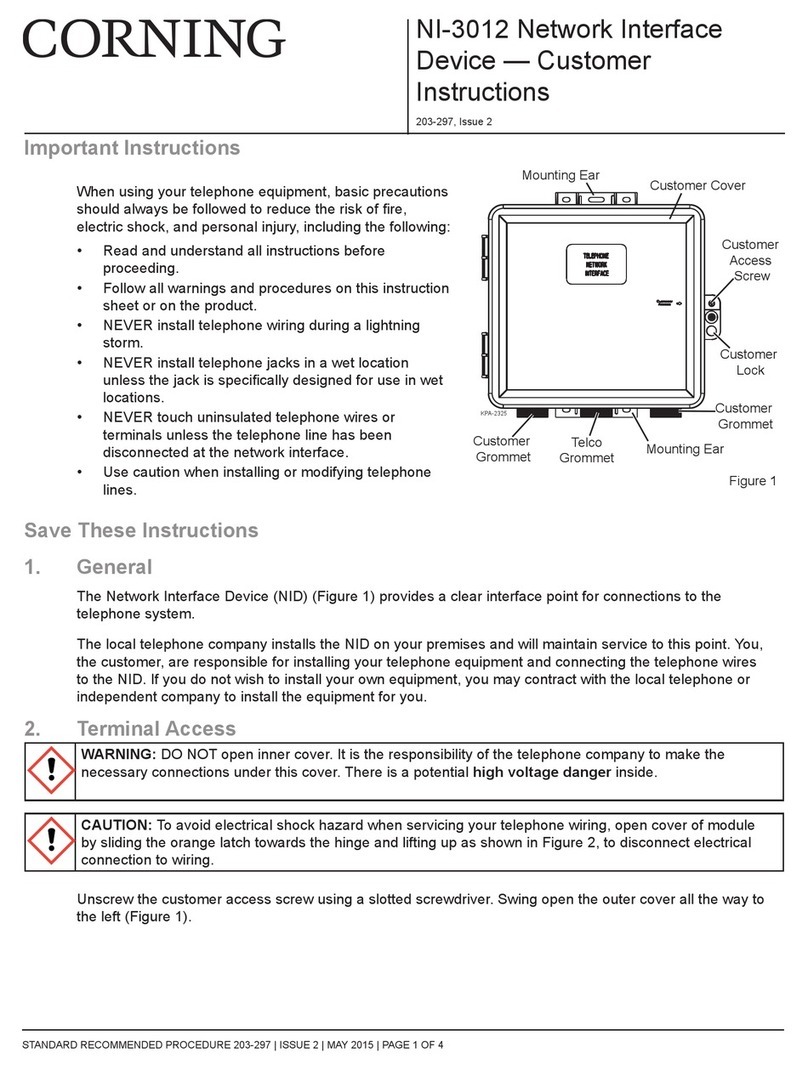
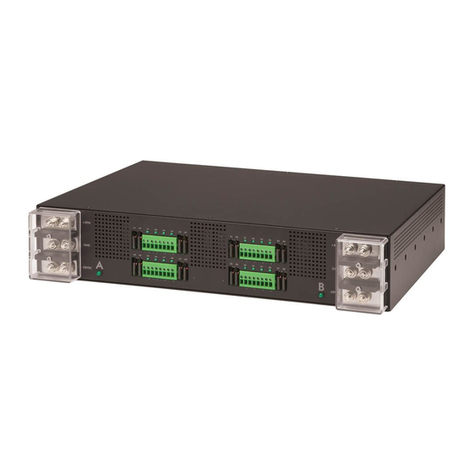
Formosa MIMO WiTDM Series User manual

1
MIMO WiTDM
®
Series
KW50-O8500
User’s Manual
2017/11/02 v2

2
Copyright
There is no any clear or implicit assurance in the user's manual of our company, including the
assurance of selling or installing for the special purpose. There are rival's volumes to carry on the
power to alter or revise in our company, if alter and forgive me for not issuing a separate notice. You
can’t duplicate any content of this manual by the written permission of our company.
About this manual
The purpose to use this manual is for install the wireless Bridge. This manual is including
disposing course and method and helping the customer to solve the unpredictable problem.
The following typographical conventions are used in this purpose:
Notice:
This indicates an important Note.
Caution:
This indicates a warning or caution
Bold Type:Indicates the function, important words, and so on.

3
Index
CHAPTER 1 INTRODUCTION ............................................................................................................................................ 4
INTRODUCTION ....................................................................................................................................................................... 4
APPEARANCE OF PRODUCT ..................................................................................................................................................... 4
FEATURES AND BENEFITS ....................................................................................................................................................... 4
CHAPTER 2 HARDWARE INSTALLATION ..................................................................................................................... 5
SYSTEM REQUIREMENT .......................................................................................................................................................... 5
PRODUCE KIT ......................................................................................................................................................................... 5
HARDWARE INSTALLATION ..................................................................................................................................................... 5
LED DESCRIPTIONS ............................................................................................................................................................... 5
CHAPTER 3 SYSTEM SETUP .............................................................................................................................................. 6
FACTORY DEFAULT SETTINGS ................................................................................................................................................. 6
USING THE WEB MANAGEMENT ............................................................................................................................................. 7
STATUS ................................................................................................................................................................................... 8
MAP .................................................................................................................................................................................... 10
SYSTEM ................................................................................................................................................................................ 11
CHAPTER 4 WIRELESS SETTINGS ................................................................................................................................ 15
BASIC WIRELESS SETTINGS .................................................................................................................................................. 15
CHAPTER 5 MANAGEMENT ............................................................................................................................................ 19
CHANGE PASSWORD ............................................................................................................................................................. 19
UPGRADE FIRMWARE ........................................................................................................................................................... 21
BACKUP/RESTORE ................................................................................................................................................................ 22
EVENT LOG .......................................................................................................................................................................... 23
REBOOT ................................................................................................................................................................................ 23
CHAPTER 6 TROUBLESHOOTING ................................................................................................................................. 24
FAQ ..................................................................................................................................................................................... 24
SERVICE SUPPORT ................................................................................................................................................................ 25

4
Chapter 1 Introduction
Introduction
Thank you for choosing the Formosa’s KW50-O8500 Wireless Outdoor MIMO WiTDM Bridge. It is a PoE
power supply, waterproof, and dust-proof wireless bridge that is specially designed for connecting among
multiple network location. The KW50-O8500 work on 5GHz, and it based on powerful TDMA technology that
provides higher channel bandwidth for long distance connect.
Appearance of Product
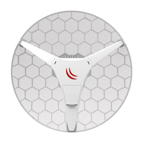
KW50-O8500
Features and Benefits
Support Power over Ethernet (PoE)
IP68 class of enclosure
Support TDMA mechanism, to ensure quality for multi-media application
Easy to install and friendly to user, just plug and play.
Provides Web-based configuration utility.

5
Chapter 2 Hardware Installation
System Requirement
Installation of MIMO WiTDM® outdoor unit of KW50-O8500 system requirement:
Two PCs with automatic speed control NIC support the transfer rate of 10/100/1000 Mbps data.
The IP address of NIC should be the same subnet with the AP, the default IP address of AP is 192.168.1.1
Microsoft Internet Explorer 6 or above.
Produce Kit
KW50-O8500 x 1
Injector-GT3 (48V, 0.65A) x 1
Mounting Kit x 1
User’s Manual CD x1
Hardware Installation
The following steps will help you while installing MIMO WiTDM®.
LED Descriptions
LED Status Description
Power Green Power ON
STATUS Green Power on Flash 1 Sec , then OFF
Remote
RSSI Green
CPE:Go around while surveying ( not connect yet ),
Represent strength of RSSI after connected.
Low ( 1 LED ) → High ( 5 LEDs )
RST Push 5 seconds then release to reset device to default
LED Definition

6
Chapter 3 System Setup
Factory Default Settings
We’ll elaborate the KW50-O8500 factory default settings. You can re-acquire these parameters by default. If
necessary, please refer to the “Restore Factory Default Settings”.
Item Factory Default
Login Information
User Name admin
Password password
Basic Settings
Device Name DEVICExxxxxx (xxxxxx Represent the last 6
digitals of the MAC address)
Ethernet Data Rate Automatic
Spanning Tree Protocol Enable
VLAN (802.1Q) Disable
IP Settings
IP Type:Manual
IP Address:192.168.1.1
IP Subnet Mask:255.255.255.0
Default Gateway:0.0.0.0
Primary DNS Server:0.0.0.0
Secondary DNS Server: 0.0.0.0
Time Settings
Time Server: None
Time Sever Port: 123
Time Zone: (GMT-08:00)Pacific Time(US &
Canada);Tijuana
Wireless Setup
Radio Frequency (RF) Enable
Operation Mode Base Station
Network ID Wireless
Time Slot 10ms
RF Bandwidth 20MHz
Channel / Frequency 5060 MHz
Data Rate SS BPSK 1/2 – SS 64QAM 5/6 , SS BPSK 1/2 – DS
64QAM 5/6
Output Power Full
Default Settings

7
Using the Web Management
The KW50-O8500 provides you with user-friendly Web-based management tool.
Open IE and enter the default IP address (Default: 192.168.1.1) and Login as below:
Login Interface
Enter the username (Default: admin) and password (Default: password) and click “Login”
Caution:
IP address of your PC must be the same subnet of device
After login, you can check basic information of device, such as MAC address off device, Firmware version, etc.
Device Information

8
Status
Select Status, you will get the information as below,
Status
System: This field identifies the current time and Coordinates.
GPS: GPS Satellites Information (Only for GPS Model)
Wireless:
MAC Address: MAC of Remote MIMO WiTDM Bridge.
IP Address: IP of Remote MIMO WiTDM Bridge.
Local RSSI: RSSI of Local Bridge.
Remote RSSI: RSSI of Remote Bridge.
Tx/Rx Rate: Current Data Rate of Tx/Rx.
Tx/Rx Modulation: Current Modulation of Tx/Rx.
How to Setup MIMO WiTDM Bridge
Get Position, Longitude and Latitude
Get Direction and Azimuth
Signal Status, In Status page, it can show remote bridge Signal Strength for local bridge (Local RSSI) and local
bridge Signal Strength for remote bridge (Remote RSSI). We can decide the best direction of antenna from
following steps:
1. We check the Local RSSI only in one side. (We call it local side.)
2. Fix remote side antenna, and adjust local side antenna. In local side, check the “Local RSSI” first, to
find a best Local RSSI and then fix the local antenna.

9
3. Adjust the Remote antenna, to find the Best Remote RSSI, and then fix the remote antenna.
4. If “Local RSSI” is changed, and worse than before, adjust local antenna again to get a best one and fix
local antenna.
5. If “Remote RSSI” is changed and worse, adjust remote antenna again.
6. Follow the same ways to get a better Local RSSI and Remote RSSI value. And Fix both side antennas.
Port Statistic:
Display Wireless and Ethernet statistics of packets including transmitted and received packets, Unicast, Broadcast,
Multicast and total Packets. Click “Refresh” can get instant information.

10
MAP
Global Positioning System, GPS (Only for GPS Model)
Select GPS, Can obtain current position from GPS receiver.
Topology
Select Topology, Can enable topology discovery protocol to establish the structure of connections.

11
System
Basic Settings
Device Name
Specify the device name, which is composed of no more than 15 characters with (0-9), (A-Z), (a-z) or (-).
Due to support WINS, You can use “Device Name” instead of IP address to access device via WEB interface. For
instance, device named as DEVICE0000FF, you can enter “DEVICE0000FF” in the IE, then click “ENTER” and
WEB page; or use “ping” command to check settings is active or not, such as ping DEVEICE0000FF.
Ethernet Data Rate
Specify the transmission rate of data, default is Automatic.
Automatic 10/100/1000Mbps / T-base10Mbps / T-Base100Mbps
VLAN
Virtual local network can promote network security. By default, the function is disabled.
GPS Coordinates (Only for GPS Model)
Obtain current position from GPS receiver.

12
IP Settings
IP Address
This IP in your network must be unique ,default is 192.168.1.1.
IP Subnet Mask
Use subnet mask to ensure two devices in the same network, default is 255.255.255.0
Default Gateway
Default gateway and DNS server for your local area network which connects to LAN port.
Primary DNS Sever
First choice of domain name server
Secondary DNS Sever
Second choice of domain name server

13
STP Settings
Enabling spanning tree can prevent undesirable loops in the network, ensuring a smooth-running network. By
default, the function is disabled.
STP Settings
Bridge priority : 0 – 65535
Hello Time : 0 – 10 seconds
Max Age : 6 – 40 seconds
Forward Delay : 4 – 30 seconds
Wireless Node Aging : 2– 300 seconds

14
Time Settings
Time Settings
Current Time
This field identifies the current time in your specific time zone.
Time Zone
Select the time zone location for your setting.
GPS Time Setting (Only for GPS Model)
Synchronize time with GPS
Internet Time Setting
Synchronize time with an Internet Time Server
Time Server Port
This field identifies the time server port like 123.

15
Chapter 4 Wireless Settings
Basic Wireless Settings
Radio Settings

16
Radio Frequency (RF)
RF-Wireless, default is enable.
Operating Mode
Bridge Point-to-Point
Remote MAC Address
Input the MAC address of Remote Bridge.
RF Bandwidth
Decide bandwidth of Radio Frequency. Including 5 / 10 / 20 / 40 MHz, default is 20MHz.
Channel / Frequency
Using different frequency
TX Power
Setting power of TX, default is max.
TX Rate Range
Normally choice transmission rate as “Best”, system will adapt best rate for real environment.
Including
Single Stream Model, SS 64QAM 5/6, SS 64QAM 3/4, SS 64QAM 2/3, SS 16QAM 3/4, SS 16QAM 1/2, SS
QPSK 3/4, SS QPSK 1/2, SS BPSK 1/2
Dual Stream Model, DS 64QAM 5/6, DS 64QAM 3/4, DS 64QAM 2/3, DS 16QAM 3/4, DS 16QAM 1/2, DS
QPSK 3/4, DS QPSK 1/2, DS BPSK 1/2
Advanced Parameters
Coverage Range: Based on Channel Bandwidth, default is 1Km
40MHz, 1-25Km
20MHz,
10MHz,
5MHz,

17
Differential Tx Rates
Setup different Tx modulation for different Clients.
Differential Tx Rates
Security Settings
Security Settings
Network Authentication
There are Open System/ WPA2 PSK to set, default is Open System.
Data Encryption
None/ AES.

18
Access Control
Access Control
Access Control Mode
Turn off/Allow/Deny
Select “Allow”, the listing clients are allowed to access the base station. Other clients are blocked.
Select “Deny”, the listing clients are blocked to access the base station. Other clients are allowed.

19
Chapter 5 Management
Change Password
Change Password
You can use the Change Password page to change the Bridge administrator's password for
accessing the Settings pages.
To change the password, Type the old password. The default password for the Bridge is:
password. Type a new password and type it again in the Repeat New Password box to confirm it.
Click Apply to have the password changed or click Cancel to keep the current password.
Remote Management
Remote Management
Bridge supports SNMP. If you use SNMP to control bridge. At first you should set SNMP settings
The KW50-O8500 supports CLI too , which could be accessed by Secure Shell (SSH). It is recommended PuTTY
be used to login.
Once the program is downloaded, open up by double-clicking. Note that before using PuTTY, be sure you are able
to connect to the MIMO WiTDM bridge.
1. Active Secure Shell(SSH). By SSH instruction setting the bridge.

20
Double-clicking Putty.
SSH. Enter IP Address of devices, check Protocol as SSH type
PuTTY Configuration
From “Connection” in the lift menu bar, click “SSH”, select”2”as “Preferred SSH protocol version”, make
“3DES” the top position in “Encryption cipher selection policy”.
Figure 16 PuTTY Configuration 2
Click “Open”, a window as below will popup:
This manual suits for next models
1
Table of contents

