Formula Sound NN106 User manual

NN106
MULTI INPUT MIXER
USERS MANUAL

NN106 INTRODUCTION
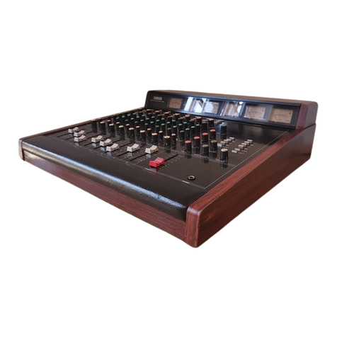
The features and layout of the NN106 are intended to provide the user with a creative tool
suitable for DJ mixing, live mixing and home studio mixing
The NN106 has 6 channels, each channel has four inputs selectable by a rotary switch, the
fourth input is fed from a single dual stereo USB input There is also a seventh input
which is the console microphone input
Channel 1 and 2 each have a low impedance microphone input on XLR sockets, stereo
line input on RCA phono sockets, balanced line input on ¼” jacks and one of the two
stereo USB inputs A recessed switch selects USB stereo channel 1 or USB stereo
channel 2 Phantom power (17V) is available for the microphones (recessed switch)
and gain adjustment (recessed)
Channels 3 to 6 each have a low impedance microphone input on XLR sockets, stereo
line input on RCA phono sockets, phono input on RCA phono sockets and one of the
two stereo USB inputs A recessed switch selects USB stereo channel 1 or USB stereo
channel 2 Phantom power is available for the microphones (recessed switch) and gain
adjustment (recessed)
Each channel has a 4 position input select switch, clip indicator LED, gain control, 3 band
“full kill” EQ, FX loop select switch, AUX switch, XFA switch, XFB switch, cue switch
and channel fader
The FX loop switch sends the signal to the FX LOOP stage in the output section, and then
onto the FX loop jack sockets, if nothing is connected to the jack sockets the signal is
automatically returned to the channel via the FX LOOP stage wet/dry control If more than
one channel has the FX loop selected then the facility is disabled, this is because if multiple
FX switches are enabled there would be multiple sends and multiple returns without a
disable mechanism so we have included circuitry to sense when more than one FX switch
is selected
The FX LOOP stage includes selectable variable frequency high and low pass filters and a
selectable compressor The variable frequency high pass filter is adjustable from 20Hz to
2Khz; the variable frequency low pass filter is adjustable from 20Khz to 2Khz
The compressor threshold is indicated by an LED and the threshold and ratio may be
adjusted by recessed pots in the base of the unit
The MIC in each channel has selectable phantom power, gain control and a recessed
switch that allows the MIC to be put on a separate MIC bus or following the normal
routing There is a recessed switch in the base of the unit that allows the MIC buss to be
included in the booth or to be fed post booth (as the console MIC), if the MIC buss is fed
post booth then it will also operate the voiceover circuit along with the console MIC
Channels 1 – 6 are assignable to cross fader, however if MIC is selected and the MIC is
selected to the MIC buss then the MIC signal will not be assigned to the cross fader The
cross fader has a fader curve control located just above the cross fader
The console MIC is upper right on the NN106 and includes recessed
phantom power switch and recessed gain trim There is volume control, 3
band EQ (+5dB to -26dB); MIC ON/OFF switch and cue switch on the
front panel
The master output is balanced stereo on XLR’s which may be strapped for

unbalanced operation with no loss of signal, master level is indicated on a
stereo 12 LED meter with volume control below the meter There is an
insert (stereo jack) in the master output enabled by a push switch and a
VOICEOVER facility enabled by a switch and operated by the console
MIC plus any channel MIC selected to the MIC buss providing the MIC
buss is set to be out of the booth
The booth output is also balanced stereo on XLR’s, the booth level is
indicated on a stereo 12 LED meter with volume control below the meter
There is also a balance pan control and mono select switch for the booth
The AUX output is balanced stereo on dual jack sockets with a level
control on the front panel
There are two headphone outputs (1/4” jack and 3 5mm jack) with volume
control and cue balance pots, a split switch is also fitted
There is a balanced stereo zone output with connection for remote zone
control panel (remote panel not included), the zone output may be switched
to mono via recessed switch
There is also record output on RCA phono sockets plus mono and sub bass
on balanced ¼” 3 pole jacks Remote mute connection is on a 2 pin
connector

Mechanical and Power Supply
Dimensions (Excluding Knobs & connectors):
Width 342mm (13 5") Height 355 3mm (14"-8RU) Depth 110mm (4 33")
Power Supply
There is a fully regulated power supply that is designed to operate on 220-240Vac or 110-
120Vac Voltage is factory set
THE POWER SUPPL MUST HAVE A MAINS EARTH CONNECTION, THE
EARTH OF THE MIXER IS TESTED BEFORE SHIPPING HOWEVER THE
USER MUST ENSURE THE POWER SUPPL THE MIXER IS CONNECTED
TO HAS A FULL FUNCTIONAL EARTH CONNECTION.
DAMAGE MA RESULT IF THE UNIT IS CONNECTED TO THE WRONG
SUPPL VOLTAGE.
Fuses
Mains fuse sizes are 1A anti-surge for 220-240Vac and 2A anti-surge for 110-120Vac
operation
It is important for safety reasons that the correct fuse ratings are always
used.
Appendixes:
Appendix 1 - Front panel detail
Appendix 2 - Back panel detail
Appendix 3 - Base adjustments
Appendix 4 – USB
Appendix 5 – Technical Specification

Input Channels
All channels have 4 inputs, the required input is selected on a rotary input select
switch at the top of the channel
Each channel has a MIC input, line input and a feed from one of the 2 USB stereo
inputs There is a single USB connector located in the output section, this takes two
stereo USB inputs which are routed to all the channels, a recessed switch adjacent to
the channel fader allows each channel to be set to either USB1 or USB2 (the first or
second USB stereo channel)
The MIC input can be routed to a MIC buss by a recessed switch below the bass EQ
control on the front panel, this MIC buss has a further control (through the back
panel) allowing it to be included in the booth or routed to the master output
(bypassing the booth) along with the console MIC If the MIC buss is bypassing the
booth the MIC buss will act with the console mic in operating the voiceover facility
(described later)
There is a clip indicator LED located between the input select and channel gain
controls
There is a GAIN control on each channel to adjust the input level and a linear channel
fader to control the level sent to the output
All channels have a “full kill” 3 band EQ, FX loop switch, AUX send switch and a
CUE select switch for headphone monitoring
There are also switches to assign the channel to one side of the cross fader marked
XFA (left) and XFB (right)
Channels
All channels have 4 inputs selected by a rotary channel input select switch at the top
of the channel Channels 1 & 2 have MIC, balanced line, line and USB (1 or 2)
Input switch position 1 is a microphone input on an XLR and has a gain adjustment
accessible through the back panel and phantom power selectable with a switch
through the base of the mixer The microphone input can also be assigned to a MIC
buss by a recessed switch through the front of the mixer (just below bass EQ control),
if the microphone is assigned to the MIC buss it will not be assignable to the cross
fader however if it is not assigned to the MIC buss it will be assignable to the cross
fader using XFA and XFB switches
Input switch position 2 is a line input on RCA phono connectors, there is a recessed
gain trim accessible thorugh the back panel

Channels 1 & 2 have a balanced stereo line input is on a pair of ¼” 3 pole jack
sockets for input switch position 3
Channels 3 – 6 have a phono input on RCA phono connectors on input switch
position 3, this phono input has an input capacitance selection switch (4 positions)
and a gain trim accessible through the back panel
Input 4 is one of the tow USB stereo inputs, the two stereo USB inputs are on a single
USB connector located on the back panel output section, the two stereo USB inputs
are routed to all channels and a recessed switch adjacent to the channel fader allows
USB1 or USB2 (USB stereo channel 1 or USB stereo channel 2) to be selected Note
there are only two stereo USB channels for the whole mixer, and each channel is may
be set for either of these two
Each channel has an FX loop switch that sends the signal to the FX LOOP stage in the
output section, and then onto the FX loop jack sockets, if nothing is connected to the jack
sockets the signal is automatically returned to the channel via the FX LOOP stage wet/dry
control If more than one channel has the FX loop selected then the facility is disabled, this
is because if multiple FX switches are enabled there would be multiple sends and multiple
returns without a disable mechanism so we have included circuitry to sense when more
than one FX switch is selected
This allows any channel to access a single FX unit connected to the FX jack sockets
by selecting that channels FX switch, only one channel at a time may access the FX
loop and if more than one channel FX switch is selected then the facility is disabled
An AUX switch sends a copy of the signal at the top of the channel fader to the AUX
output, if several AUX are selected the AUX signals are summed There is an AUX
output level control in the output section
The XFA and XFB switches assign the channel signal to a side of the cross fader
(XFA is left and XFB is right), when a channel has microphone selected and the
microphone is assigned to the MIC buss then no mic signal is assigned for that
channel to the cross fader (the MIC buss goes direct to the output)
The CUE switch sends a copy of the signal at the top of the fader to the headphones
in the output section and the CUE meter in the output section indicates the level
providing only one CUE switch is selected (if more then one CUE switch is selected
then the signals are summed and the summed signal level is indicated)
USB input
The USB input is type B connector The USB input module is an Amanero
Combo384 Module (See www amanero com website for full specification) operating
up to 192Khz

The I2S output from the Amanero USB module is converted to audio by a Formula
Sound Ltd designed DAC based on Texas PCM1502 integrated circuits
The output from the Amanero USB module is digitally isolated from the Amanero
USB module reducing any noise from the USB connection (the USB earth is isolated
from the NN106 earth)
The Amanero USB module provides 2 stereo channels, these 2 channels are routed to
all 6 channels of the NN106 and each channel can selects USB stereo 1 or USB
stereo 2 on a recessed switch
Output Section
Console microphone
The output section includes the 7th input, a console microphone, the console
microphone input is on XLR and there is a gain trim and phantom power switch
The console microphone has a 3 band EQ (not full kill), gain control, MIC ON switch
and CUE The console microphone is routed directly to the master and is not included
in the booth output
Headphone monitoring
Any CUE selection on the inputs sends a copy of that input to the headphone section,
if multiple input CUE switches are selected those inputs are summed together
The CUE/BAL control selects the CUE content or the master signal to be sent to the
headphones (setting the control part way gives a mix of master and CUE signals in
proportion to the position of the control eg mid is 50:50)
The split control gives CUE in the left ear and master signal in the right ear of the
headphones when the CUE/BAL control is in the CUE position
There are 2 headphone outputs, a stereo ¼” jack socket and a 3 5mm jack socket, the
headphone impedance on each should be no less than 32 Ohms
The headphone volume control is marked PHONES, the level from the headphones is
also dependent on the settings on the rest of the mixer and of course the level of the
input signal
Hearing damage is caused by loud sound, the louder the sound the shorter the
length of time to cause permanent hearing damage. Always start with the
PHONES control at a quarter turn and increase as required.
The UK acceptable sound level for employees on an 8 hour shift is 86dB(A).

Master output
The master output is on a pair of balanced XLR connectors, there is a 12 LED stereo
meter and volume control labelled MASTER
There is a voiceover facility in the master section which allows a signal on the
microphone buss to automatically reduce the music level by an adjustable amount
The voiceover is selected on a switch, the microphone level that triggers it is set by
the sensitivity pot and the amount the music is reduced is set by the attenuation pot
The microphone buss consists of the console microphone signal plus any channel
microphone inputs that are assigned to the microphone buss
There is also an insert in the master output stage on a pair of ¼” jack sockets, the
insert is enabled by a switch marked INSERT
Note the send path is always active, the insert switch bringing in the return path
Booth output
The booth output is on a pair of balanced XLR connectors; there is a 12 LED stereo
meter and volume control labelled BOOTH
There is a MONO select switch that sums the booth left and right to mono There is a
PAN control that operates in stereo mode, with MONO selected the PAN pot has no
effect
FX LOOP
Each channel has a FX switch, when one channel is selected that channel is sent to
the FX loop and the return from the FX loop routed back to that channel (Selecting
FX on more than one channel disables the facility)
The FX loop has variable frequency high and low pass filters (enabled by a switch)
and a compressor (enabled by a switch) The compressor has preset threshold and
ratio that is preset by pots through the back panel
The FX loop goes to FX send return jacks on the back panel, the jacks are switching
so if no FX unit is connected the send signal is automatically returned
The FX return goes to a wet/dry pot (along with a copy of the send signal), the
wet/dry pot setting determines how much original signal and how much FX return is
sent back to the channel with FX selected In the wet position the signal is the FX
return signal

AUX
The AUX contains a summed signal of each channel with AUX selected, the level of
the summed AUX 1 signal is adjusted by the volume control marked AUX The AUX
signal is balanced stereo on a pair of ¼” jack sockets
ZONE output
A balanced stereo zone output is provided on a 6 pin rectangular connector, the zone
output is controlled by a remote panel (not included) that connects to an adjacent 3
pin rectangular connector
Balanced Zone output on the 6 way connector, left pin 1 + pin 2 0V/grnd Pin 3 -,
right pin 4 + pin5 0V/grnd pin 6 -
The remote panel (not included) may be located up to 30 metres from the mixer and
allows the zone volume to be controlled entirely separately
Remote panel pin 3 is 0V/grnd, pin 2 and 1 connect to the wiper of the pot providing
the volume control
Crossfader
The crossfader has signals assigned to it by the XFA and XFB controls on input
channels 1 – 6 If multiple XFA and/or XFB switches are selected then those signals
are summed at the crossfader
XFA signals are sent to the left of the cross fader and XFB signals are sent to the
right of the cross fader If one or both sides has no signals assigned then that side will
have no signal
The signal from the crossfader that is routed to the output is dependent on the
position of the crossfader, with crossfader set full left any XFA selection is sent to the
output and with the crossfader full right any XFB selection is sent to the output
With the crossfader in centre position equal amounts of XFA and XFB will be sent to
the output, with the crossfader off to one side (but not at end) a mix of XFA and XFB
will be sent to the output The relative level of XFA and XFB will depend on the
position of the crossfader, more to the left and XFA will be larger and more to the
right and XFB will be larger
The rate at which the signal changes from XFA to XFB as the crossfader moves left
to right (or vice versa) can be adjusted by the contour control
A recessed switch in the base of the unit can switch the crossfader off

MONO and SUB BASS outputs
There is a pair of ¼” 3 pole jacks on the back panel with balanced outputs for mono
and sub-bass
Record output
A record output is provided on a pair of RCA phono sockets
Remote mute
The remote mute connection is on a 2 pin rectangular connector, shorting pin 1 and
pin 2 will mute the mixer with the exception of the console microphone and any
channel microphones set to MIC buss with MIC buss selected post booth
This may be used to interface to a fire alarm, if the alarm has a set of isolated contacts
that close on alarm then these may be used directly, otherwise an isolating interface
relay will be required
SET UP GUIDE
Use the channel back panel gain trims (MIC, Line, Phono) to set the inputs from your
equipment to be reasonably near equal when each type of input is selected while at
the same time ensuring the maximum level at the output is not approaching clipping
Channel and console MICs all have phantom power switches (17V), so check if your
mics require phantom power and select for those inputs accordingly
Channel microphones can be sent to the mic buss or included in the stereo mix, when
sent to the mic buss they are not available for cross fader assignment
The microphone buss can be routed into the booth or routed to bypass the booth, the
console mic always bypasses the booth
The channel mic assignment switch and booth bypass switch gives flexibility in how
the microphones are routed
Choose which USB stereo channel is routed to each channel, it may be you only use 1
stereo USB channel in which case you would select USB1 for all channels
The compressor has recessed pre-sets in the base of the mixer, if adjustment is
required the following approach is suggested Play a CD with a piece of music that is
reasonably even level on say channel 3, route channel 3 to FX and select compressor
and set FX loop wet/dry pot to wet Set channel 3 cue on

Use the channel gain pot to set the music to the level you want the compressor to
operate at (threshold level), now lift the mixer and adjust the compressor threshold
pot until the threshold (THR) light just above the compressor button just comes on
Now turn up the channel gain pot and adjust the compressor ratio pot to the
compression level you require (pot at minimum will be no compression so note the
CUE meter reading at this point and then turn the compressor pot reducing the level
until you achieve the compression you require So a 6dB reduction in metered level
when adjusted will mean 2:1 compression
Generally the factory setting is suitable for most uses of the compressor but following
this routine should help if you want an individual setting
Formula Sound Limited
Unit 23; Stadium Business Centre
North End Road
Wembley
HA9 0AT
Tel 0208 900 0947 FAX 0208 903 6283
Email info@formula-sound co uk
Web www formula-sound co uk


APPENDIX 4
USB operations
For windows user it is necessary to download drivers, for MAC it is ready to use.
T e drivers are located on www.superstereo.co.uk in t e download section marked
DOWNLOAD Drivers for windows.
Note Superstereo is owned by Formula Sound Ltd, t e USB in t e NN106 is t e
same as t e USB in t e Superstereo DN78.
1 For windows download t e driver.
2 Unzip t e file into a folder of your c oice.
3 Open folder Superstereo windows driver 2, and t en Superstereo driver folder.
4 Run eit er setup 32 for windows XP or run setup64 for 64 bit versions of windows
(windows 7 and later).
5 Follow on screen instructions, pressing install option w en asked to install driver
software.
6 A message will pop up to say t e Superstereo driver is installed.
7 Once you ave pressed t e finis button, you can t en connect to t e NN106 USB
port.
8 To configure t e soundcard for use goto Hardware and Sound in t e control panel
and click on Manage audio devices.
9Select SUPESTEREO speakers option and click configure.
10 For 4 c annel operation (2 stereo c annels) click on Quadrop onic, for 2 c annel
(one stereo c annel) operation click on stereo.
11 Click finis to complete.
12 To c ange your sample rate and quality repeat steps 8 but click on properties
instead, t en click on advanced.
13 Select your desired sample rate and bit rate.
14 Your NN106 is now ready to use.
For MAC
1 Plug into NN106
2 Open MIDI and audio setup
3 Select superstereo driver and select t e required sample rate up to 192K z.
4 Go into configuration and select eit er 4 c annel (2 stereo c annels) or 2 c annel
mode (one stereo c annel).
5 Your NN106 is now ready to use.
T e USB will work wit a range of DJ software suc as Traktor.

APPENDIX 5
Technical specification
All figures are at 230V setting and 20 C room temperature.
Power suppl 230V +/- 10% or 115V +/- 10%.
Parameter Rating
Noisefloor, 0dB output setting channel faders down <-80dB
Phono noise floor, 0dB setting, 1 channel fader up. <-56dB
(Deck connected)
Mic input, 0dB setting EIN <-120dB
Distortion, line input at 0dB, 0dB out <0.01%
EQ in mid position 20Hz – 20KHz <+/- 0.5dB
Phantom power 17V+/-0.5V

FORMULA SOUND LIMITED
UNIT 23; STADIUM BUSINESS CENTRE; NORTH END ROAD; WEMBLEY; MIDDLESEX; HA9 0AT
TELEPHONE +44 (0)208 900 0947 FAX +44 (0)208 903 8657
www.formula sound.co.uk email info@formula sound.co.uk
E.U. CERTIFICATE OF CONFORMITY
We declare that the products listed conform to the following directives and standards
89/336/EEC amended by 92/31/EEC and 93/68/EEC
BS EN 50082 1 BS EN 50081 1
PRODUCT TYPE
NN106
The CE mark was first applied in 1995
igned
B. J. Penaligon General Manager
Attention
The attention of the specifier, purchaser, installer, or user is drawn to the fact that good wiring practice
must be observed when connecting the above equipment. Good quality connectors and screened cables
must be used for all audio connections. Twin screened cables should be used for all balanced lines.
THI EQUIPMENT MU T BE EARTHED
CONSULT THE USERS MANUAL FOR TECHNICAL DETAILS
Table of contents
Other Formula Sound Mixer manuals
