FORNI CLASSICO 80 G User manual

www.stefanoferraraforni.it
CLASSICO GAS
INSTALLATION AND OPERATING MANUAL
CLASSICO GAS 80 – 90
MLF GAS 80 – 90
SOMMA GAS 80 – 90
VULCANO GAS 80 – 90
PLEASE READ ALL INSTRUCTIONS BEFORE INSTALLING AND USING
THE APPLIANCE
A MAJOR CAUSE OF OVEN-RELATED FIRE IS FAILURE TO MAINTAIN
REQUIRED CLEARANCES (AIR SPACES) TO COMBUSTIBLE
MATERIALS. IT IS OF UTMOST IMPORTANCE THAT THIS OVEN BE
INSTALLED ONLY IN ACCORDANCE WITH THESE INSTRUCTIONS.
SAVE THESE INSTRUCTIONS
Vers. 1.2
Stefano Ferrara Forni S.R.L.
Forni a legna artigianali
Neapolitan handmade brick ovens
Via Provinciale Pianura, 2 – int.12
80078 Pozzuoli, Napoli
Tel./Fax: +39 081 876 1664
e-mail: info@stefanoferraraforni.it
P.IVA 06771801211
C.C.I.A.A. 838246

2
www.stefanoferraraforni.it
Table of content
Page
- Introduction .............................................................................................................................................................. 3
- Installation operating and maintenance preface ...................................................................................................... 5
- Features .................................................................................................................................................................. 6
- Models and sizes ..................................................................................................................................................... 7
- Instruction for lifting and moving oven ..................................................................................................................... 9
- Packaging removing and placement oven on support stand ………………………………….... ................................ 11
- Installation procedures
•General information …………………………………………………………………………..... .......................... 12
•Stand covering installation (optional for Classico,Somma, Vulcano models)………………………………… 13
•Stand covering installation for MLF model………………………………… ................................................... 14
•Installation lateral marbles .......................................................................................................................... 17
•Burner installation....................................................................................................................................... 18
- Connections
•Electrical connection ………………………………………………………………………….............................. 21
•Gas connection …………………………………………………………………………...................................... 22
- Sample of LPG system ……………………………… ................................................................................................ 24
- Oven venting …………………………………………………………………………………………….............................. 25
- Oven care during first fires …………………………………………………………………………… .............................. 26
- Use of the oven with wood ...................................................................................................................................... 27
•Maintenance and cleaning ......................................................................................................................... 28
- Burner components.................................................................................................................................................. 29
- Control panel............................................................................................................................................................ 30
- Celsius/Fahreneit change ....................................................................................................................................... 31
- First ignition and adjustment .................................................................................................................................... 32
•First burner ignition ..................................................................................................................................... 32
•Cooking temperature setting....................................................................................................................... 33
•Low flame gas adjustment .......................................................................................................................... 33
•Air adjustment............................................................................................................................................. 34
•Setting safety limit temperature ................................................................................................................. 36
•Burner operation with control panel ............................................................................................................ 37
•On/Off function .......................................................................................................................................... 37
•High flame power adjustment .................................................................................................................... 37
•Switching the burner OFF through control panel ........................................................................................ 38
•Error messages ......................................................................................................................................... 39
- Maintenance ............................................................................................................................................................ 40
•Routine maintenance ................................................................................................................................. 41
•Special maintenance ................................................................................................................................. 42
- Burner gas conversion ............................................................................................................................................. 43
•Conversion on control panel ...................................................................................................................... 43
•Nozzles replacement .................................................................................................................................. 43
•Flame arrestor replacement ....................................................................................................................... 44
- Replacing components
•Sit control equipment replacement ............................................................................................................ 45
•Probe replacement .................................................................................................................................... 47
•Control Unit fuse replacement .................................................................................................................... 47
•Detection electrode replacement ................................................................................................................ 47
- Error messages ....................................................................................................................................................... 48
- Troubleshooting ....................................................................................................................................................... 49
•Control unit doesn’t switch on..................................................................................................................... 49
•Control unit turns on but the burner doesn’t start ...................................................................................... 49
•Control unit turns on, the spark strikes, low flame doesn’t turn ON and the burner blocks ........................ 49
•The control unit turns ON, low flame turns ON but the burner blocks and flame turns OFF ...................... 50
•Low flame turns ON but after 15-20 seconds high flame does not turn ON................................................ 50
•Probe fault led turns ON ............................................................................................................................. 50
•Red display with “- - -”................................................................................................................................. 51
•Green display: Set T° does not increase ................................................................................................... 51
•Slower heating than the normal parameters .............................................................................................. 51
•Soot under the dome ................................................................................................................................. 52
- Control unit diagram................................................................................................................................................. 53
- Connections diagram .............................................................................................................................................. 53

3
www.stefanoferraraforni.it
INTRODUCTION
This manual has been made so that the user of the oven can work in complete safety.
THE USER HAS OBLIGATION TO READ CAREFULLY AND TO OBSERVE CAREFULLY THE
INSTRUCTIONS OF THE MANUAL.
Failure to comply with the instructions contained in this manual, means to operate in the conditions of use
not foreseen by the manufacturer.
THE MANUFACTURER IS NOT LIABLE FOR ANY DAMAGES CAUSED BY THINGS OR PERSONS,
DUE TO THE FAILURE TO OBSERVE THE INSTRUCTIONS AND THE RECOMMENDATIONS IN THIS
MANUAL.
The manual must be kept in good condition and must always be available for quick reference in case of
need.
THE MANUAL IS OF OWNERSHIP OF THE MANUFACTURER AND CANNOT BE REPRODUCED EVEN
PARTIALLY, AS WELL AS IT CANNOT BE DIFFUSED OR USED FOR ADVERTISING PURPOSE OR
SHARED WITH THIRD PARTIES.
ANY TRANSGRESSION WILL HAVE CIVIL AND PENAL SANCTIONS AS A CONSEQUENCE.
EXPLANATION OF SYMBOLS AND WARNINGS
SYMBOL DESCRIPTION
Symbol used to identify information of particular importance within the manual. The
information also concerns the safety of the personnel involved in the use of the
machine.
Symbol used to indicate passages of technical importance in the instructions and
warnings or procedures related to operator safety.
Symbol used to indicate warnings or procedures related to electricity.
NOTE ON THE PRODUCT
The aim of the manufacturing company is to make ovens that meet the current technical state. So we always
take care of our products even after delivery.
For any problems or inconveniences contact the service center:
Email: info@stefanoferraraforni.it - tel. +39 081 876 16 64

4
www.stefanoferraraforni.it
INTRODUCTION ABOUT INSTRUCTIONS OF WORKING
These instructions have the task of allowing and facilitating the safe and appropriate use of the OVEN and of
exploiting the regulatory use possibilities provided.
Their observance helps to avoid dangers, repair costs, to reduce off-duty times and to increase the lifespan
of the device.
Operating instructions are to be followed also taking in consideration the regulations on accident prevention
and environmental protection valid in the country of installation
BUYER'S OBLIGATIONS
The buyer is obliged to:
• Observe the national regulations concerning workplace safety;
• Observe the instructions contained in the manual.

5
www.stefanoferraraforni.it
INSTALLATION OPERATING AND MAINTENANCE PREFACE
WARNING !
READ THIS ENTIRE MANUAL BEFORE YOU INSTALL THE OVEN. FAILURE TO
FOLLOW INSTRUCTIONS MAY RESULT IN PROPERTY DAMAGE, BODILY INJURY, OR
EVEN DEATH.
•When this oven is not properly installed, a fire may result. To reduce the risk of fire, follow the
installation instructions
•Contact your local building or fire officials for clarification on any restrictions on installation of this
oven in your area, or need for inspection of the oven installation.
•DO NOT close the oven door while a fire is in the oven.
•Place the door over the oven opening after cooking is completed at the end of the work day.
•Hot while in operation. Keep children, clothing and furniture away. Contact may cause skin burns.
•Do not burn garbage or flammable fluids.
•Smokes of the burning must be expelled through a flue system conform to the local rules.
•Do not connect the oven to a chimney flue serving another appliance.
•Keep children and pets away from hot oven.
•DO NOT USE products not specified for use with this oven.
•DO NOT USE liquid fuel (firelighter fluid, gasoline, lantern oil, kerosene or similar liquids) to start or
maintain a fire.
•DO NOT use water to dampen or extinguish fire in the oven.
•Keep a proper extinguisher (class A) close to the oven at all times.
•Instruct all personnel about location and use of the fire extinguisher and proper fire emergency
procedures.
•DO NOT pack required air spaces with insulation or other materials.
•DO NOT expose the oven to the weather, if the oven is installed outdoors to shelter it under a
canopy.
•The oven is meant only for cooking pizza and/or bread it is not recommended for cooking other food
or food in pan ,chafe of metal pans can get the floor soon damaged and grease spatter from
roasting can be absorbed from the floor that lose its correct properties of cooking.
•DO NOT pack required air spaces with insulation or other materials.
•In case of use of the oven with wood use only well dried wood.
•In case of use of the oven with wood, use a metal shovel to remove the ashes and place them in a
metal bin with a tightly fitting lid. The container should be stored on a non-combustible surface, away
from all combustible materials. Ensure ashes are completely cold before disposing of them
appropriately.
•DO NOT expose the oven to the weather, if the oven is installed outdoors to shelter it under a
canopy.
•The oven is meant only for cooking pizza and/or bread it is not recommended for cooking other food
or food in pan ,chafe of metal pans can get the floor soon damaged and grease spatter from
roasting can be absorbed from the floor that lose its correct properties of cooking
SAVE THESE INSTRUCTIONS

6
www.stefanoferraraforni.it
FEATURES:
Plain of cooking: Biscotto di Sorrento
Crown and dome: Refractory bricks 60 mm. thick, temperature resistance over 900°C (1650F)
External hood: Handmade Santa Maria Bricks
Support stand: Reinforced and painted iron structure (four legs)
External covering: Mosaic tiles – palladiana marble
Electronic burner with one modulating flame max thermal capacity kW 24 – kcal/h 20.640
Temperature range of working: 0 °C – 500 °C (32F – 392F)
Electronic unit control for temperature management
Alimentation: Gas
Gas consumption at max. temperature:
- Natural gas: 2,54 Nmc/h
- LPG : 0,86 Nmc/h
Flue output: Ø 250 mm.
Max heat output: 20.640 kcal – 24 kW
Smokes temperature output: 190 °C (374 F)
Extract air flow: 650 mc/h (at starting)
500 mc/h (at full operating)
Required CFM: 380
Venting: Natural draft
Electrical supply: 230 V – 50/60 Hz one phase
Electrical absorption: 100 Watt
Gas connection: ½ inch
Gas pressure:
- Natural gas: from 15 mbar - to 25 mbar
- LPG: from 25 mbar - to 50 mbar
It’s required a direct connection of the tube that serves the oven from gas meter to the oven no other
equipment must be installed on the same line between the meter and the oven.
For the gas line use the follows pipes size:
- Distance from the gas meter to the oven until 10 meters (32 ft) use:
For LPG ½” pipe
For Natural gas ¾” pipe
- Distance from the gas meter to the oven over 10 meters (32 ft) use 1” pipe (independently to the
gas in use)

7
www.stefanoferraraforni.it
MODELS AND SIZES
CLASSICO
MLF

8
www.stefanoferraraforni.it
SOMMA
VULCANO

9
www.stefanoferraraforni.it
INSTRUCTIONS FOR LIFTING AND MOVING OVEN
FOR OVENS ALREADY INSTALLED ON THE SUPPORT STAND
1- USING A FORKLIFT
Determine if forklift capacity is sufficient to lift oven. (See pag. 7-8 for weights and sizes)
Prior to lifting, make sure the forks are long enough as whole diameter of the oven, if not fork extensions
should be used.
Keep forklift straight. Carefully place forks on the back of the oven through the stand legs
and position under the oven. Slowly lift and move the oven as needed
WARNING: MAKE SURE NOT TO DAMAGE THE BURNER DURING INSERTING THE
FORKS BETWEEN THE STAND LEGS.
2- USING A PALLET JACK
Determine if pallet jack capacity is sufficient to lift oven. (See pag. 7-8 for weights and sizes)
Prior to lifting, make sure pallet jack is long enough to reach both horizontal angles at lower end of steel tube
support legs. Place pallet jack on the back of the oven , place the forks between tube steel support legs
under horizontal angles.
Carefully lift oven and move slowly.

10
www.stefanoferraraforni.it
INSTRUCTIONS FOR LIFTING AND MOVING OVEN
FOR OVEN SEPARATED FROM THE SUPPORT STAND
1- USING A FORKLIFT
Determine if forklift capacity is sufficient to lift oven. (See pag. 7 – 8 for weights and sizes)
Prior to lifting, make sure the forks are long enough as whole diameter of the oven, if not fork extensions
should be used.
Under the oven there are four little steel feet 4” (10 cm) high to permit placing of the forks.
Keep forklift straight. Carefully place forks through the steel feet and position under the oven. Slowly lift and
move the oven as needed.
2- USING A PALLET JACK
Determine if pallet jack capacity is sufficient to lift oven. (See pag.7 - 8 for weights and sizes)
Prior to lifting, make sure the forks are long enough as whole diameter of the oven.
Place pallet jack between the steel feet and position under the oven.
Carefully lift oven and move slowly.
.
WARNING : ONLY VERTICAL LIFTING IS ALLOWED DO NOT TURN UPSIDE
DOWN THE OVEN

11
www.stefanoferraraforni.it
PACKAGING REMOVING AND PLACEMENT OF THE OVEN ON SUPPORT STAND
On the bottom of the crate (front side and back side) there is the required space for insert the forks of the
forklift. (photo 1)
The crate is fixed to two metal brackets placed under the oven (photo 2)
photo 1 photo 2
Once removed the crate, in order to remove the brackets, lift the oven with a forklift and unscrew the bolts.
Note the removed bolts (17 mm.- 0.67 in hexagonal head screw) will be the same to use for fixing the oven
on the support stand, so preserve them for the next use.
Lift the oven with a forklift until a above the height of the metallic support stand
Let down carefully for inserting the steel feet placed under the oven into the legs of the support stand
respecting the marked letters :
- Front : A – A
- Back : B – B
Once placed the oven on the support stand to screw the furnished screws (17 mm.- 0.67 in hexagonal head
screw) in the existing holes on the back of each stand leg.
.
12
www.stefanoferraraforni.it
INSTALLATION PROCEDURES
1. Be sure to have a sufficient space in the desired location for the oven.
See pag. 7 – 8 for minimum space required according the model.
2. Place the oven on appropriate floor able to support the oven weight.
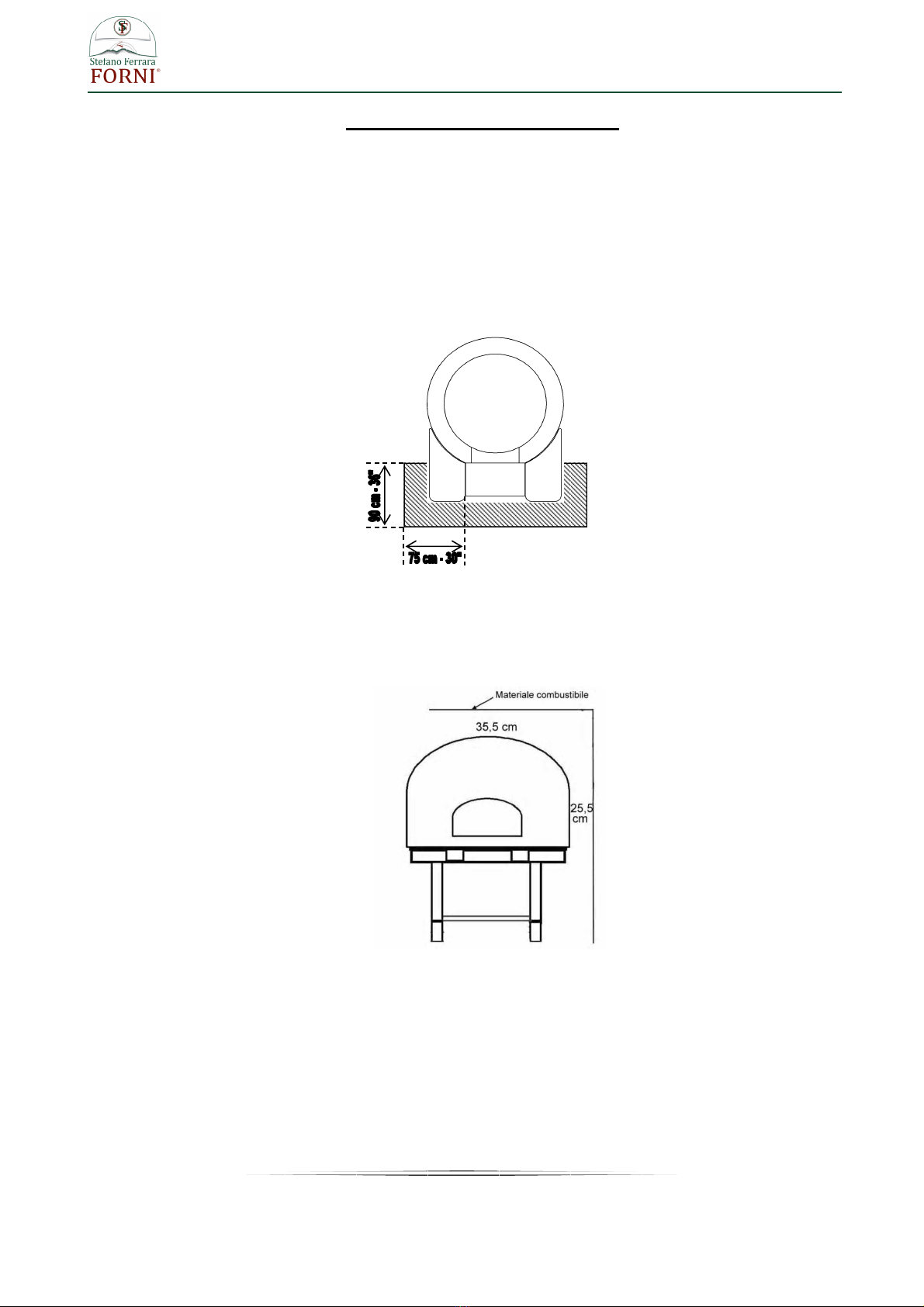
3. Any adjacent combustible floor which projects in front of the oven opening must be a minimum of 30
inches (75 cm) away from each side of the door opening and 36 inches (90 cm.) from the front of
the door opening.
4. It is essential to maintain clearance space between the oven components and any combustible
material, such as walls and ceilings.
The oven must have a minimum 10” (25,5 cm.) clearance to combustibles from all sides and 14"
(35,5 cm) clearance to combustibles from the top.
Warning : Don’t place any type type of insulation in the required clearance spaces surrounding the
oven
13
www.stefanoferraraforni.it
5. Stand covering installation (optional for models Classico, Somma e Vulcano)
For such working below listed tools are required:
a) Spanner for hexagonal head screws 10 mm. (0.40 in)
b) Spanner for hexagonal head screws 13 mm. (0.51 in)
c) Spanner for hexagonal head screws 17 mm. (0.67 in)
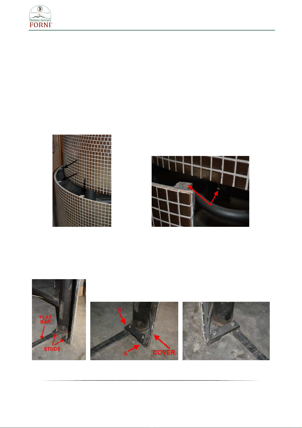
The stand leg covering is provided of some small holed metallic bands (photo 1) to fix at the bottom of the
oven with the furnished screws (Hex head self-threading screw mm. 10 – 0.40 in)
Place the cover getting the holes of the metallic bands and the holes of metallic ring underneath the oven
coincide between them (photo 2) , to screw the provided screws.
photo 1 photo 2
Fasten the front part of the cover to the flat bar of conjunction placed between the two front stand legs
The terminals of the flat bar and the bottom of the frontal cover arch are provided of pre welded studs,
connect these points with the bar ending 45 degree cut .
The 45 degree terminal of the bar (A) is to be fastened to the cover , the terminal with straight ending (B) is
to be fastened to the flat bar . Screw with the provided hexagonal nuts mm. 17 (0.67in)
photo 3 photo 4 photo 5
14
www.stefanoferraraforni.it
Fasten the sides of the cover to the two lateral cross tubes of the metallic support stand using the stirrup like
on the photo 6
photo 6 photo 7
The curved terminal of the stirrup is to be overlapped to the cross tube (photo 7) getting joint the hole of the
stirrup with the hole existing on the cross tube, screw with the provided hexagonal head screws 10 mm.
The opposite terminal of the stirrup must overlapped and fastened on the pre welded bar placed on the side
of the cover . Screw with hexagonal head screw 13 mm.(0.51 in)
On the top and internally to the front arch of the cover two metal fins are welded, insert hexagonal head
screw mm. 13 and screw well so to get perfect joint of the edges
5.1 Installation of stand covering for MFL model
For such working below listed tools are required:
a) Spanner for hexagonal head screws 10 mm. (0.40 in)
b) Spanner for hexagonal head screws 13 mm. (0.51 in)
c) Spanner for hexagonal head screws 17 mm. (0.67 in)
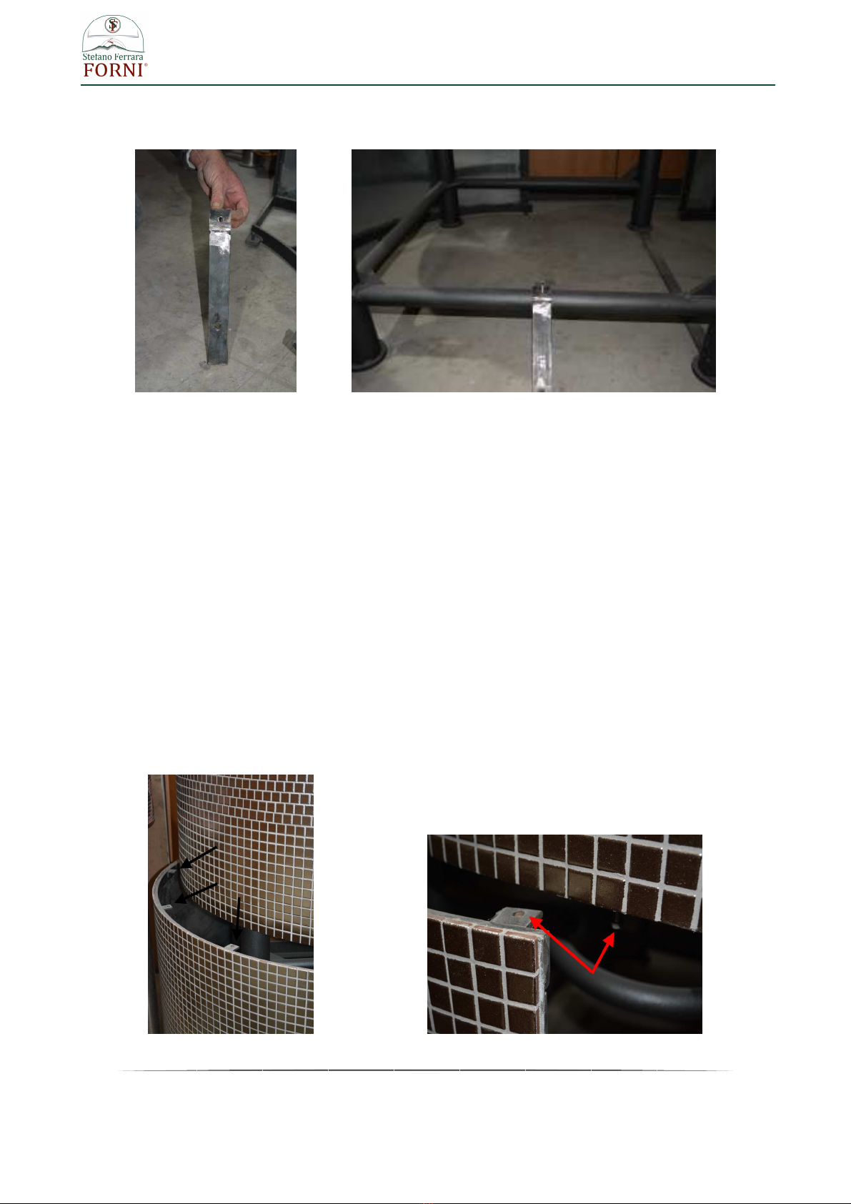
Install the back paneling , it’s provided provided of some small holed metallic bands(photo 1) to fix at the
bottom of the oven with the furnished screws (Hex head self-threading screw mm. 10 – 0.40 in)
photo 1 photo 2

15
www.stefanoferraraforni.it
Place the paneling getting the holes of the metallic bands and the holes of metallic ring underneath the oven
coincide between them (photo 2 previous page), to screw the provided screws. (Hex head self-threading
screw mm. 10- 0.40 in)
Once installed the back panel install the front panel that is provided of junction points like shown on photo 3
photo 3
Install the front paneling getting its edges to coincide with the edges of the back panel already assembled
Match the hole of the point “1” (see photo above) with the holes of metallic ring underneath the oven and
screwing the provide screw (hex head self-threading screw mm. 10 – 0.40 in)
The paneling is provided of some studs on the top and on the sides (see point 2 and 5 photo 3) and the
same studs are welded on the internal side of the perimeter metallic ring underneath the oven and on the
sides of the back paneling.
Put the metallic bands into the studs (photo 4) and screwing the provided hexagonal nuts mm. 13 – 0.40 in
(photo 5)
photo 4 photo 5

16
www.stefanoferraraforni.it
Screw the stirrup with curved end (point “3” photo 6) to the iron tube of the oven stand (photo 7) using hex
head self-threading screw mm. 10 – 0.40 in
photo 6 photo 7
Join the point 4 of the front stand cover (photo 8) to the stand using the metallic stirrup with 45 degrees end .
The stirrup side with 45 degree end must be fixed on the point 4 of the cover (photo 8) the other side with
straight end must be fixed to the prewelded screw on the junction band between the stand legs (photo 10 –
11)
For screwing use the provided hex nuts mm. 17 (0.67 in)
photo 8 photo 9
photo 10 photo 11

17
www.stefanoferraraforni.it
Fasten the sides of the oven stand cover to the cross tubes of the same stand with the stirrup showed on the
photo 12
photo 12 photo 13
The curved end of the stirrup must be overlapped on the cross tube of the support stand (photo 13) , get
matched the hole existing on the stirrup and the hole existing on the tube then screwing with the provided
hex screw mm. 10 (0.40 in)
The opposite terminal of the stirrup must be overlapped and fastened to the stirrup existing on the stand
cover (point 6 photo below) using the provided hex head 13 mm screw .
6) Installation of lateral marbles
Lateral marbles come into a separate package
Fasten the marbles on the metallic plate existing at the sides of the oven mouth using some silicone and
waiting complete drying before use them as support shelf

18
www.stefanoferraraforni.it
7) Burner installation
7.1 Temperature probe
The temperature probe “A” is inserted in a copper tube “B” .
Insert the probe through the copper tube “C” placed under the oven until getting it in the cooking room to a
height of around 1 cm (0.40 in). The probe must protrude not more than 1 cm from the oven floor.
Once placed the probe into the oven , connecting the copper tube “B” that comes from the unit control to the
tube “C” under the oven.
7.2 Burner
Before installing the burner , check the correct position of the electrode of the burner by following the below
procedure :
photo 1 photo 2
Check that the burner electrode discharge the spark onto the edge of the “A” circumference of one of the
holes of the external series of the flame breaker. (photo 1)
The tip of electrode “B” must be at a distance of 3 mm (0.12 in) from the surface of flame arrestor “A”. (photo
2)

19
www.stefanoferraraforni.it
Insert the burner in the hole under the oven making sure the holes of the fixing flange (“A” photo 3) coincide
with the existing pivots on the sides of the burner hole (“B” photo 3)
To screw the nuts (hexagonal nut 13 mm – “C” photo 3 ) until to fix strongly the burner
photo 3
The control panel complete of electrical cables and temperature probe (photo 4) is already installed on the
support stand of the oven
photo 4
Connect the burner to the control panel inserting the connectors A and B into the sockets placed on the
bottom of support plate of the control equipment (photo 5 next page)

20
www.stefanoferraraforni.it
photo 5
Connect the gas to the gas inlet Ø1/2” of the burner (point C – photo 5) and the blue plug ( C photo 4) to a
CEI 220V. 16A. 50HZ. electrical socket.
When requested a transformer is provided for allowing the working of the burner with different voltage than
220 V . In this case the electrical cable isn’t provided of any blue plug (C photo 4) and it will be need
connect to the cable an appropriate plug can be inserted in the existing socket on the place of installing oven
Take care to not exchange phase - neutral connection
Electrical lines must be placed sufficiently spaced from the hot parts of the oven
INSTALLATION ROOM VENTILATION:
The room where the oven is installed must be equipped with a suitable air intake that cannot be closed or
tampered with ( windows and doors cannot be considered suitable air intakes).
Direct air intake:
- rectangular opening: 200 mm x 200 mm (8 in x 8 in)
- round opening: Ø 250 mm (10 in)
If there is an extractor hood in the room, you need to increase the air intake by considering the air amount
extracted from the hood (according to its label) and considering that the burner requires 30-40 m ³ of air per
hour during operation (17.66- 23.50
ft
3
/min)
. If the air intake is too little, pressure variations are generated
and the burner may not work properly.
DRAUGHTS
The room must not have draughts that can cause malfunctions, such as an irregular flame or burner switch-
off: in the presence of draughts, that cannot be eliminated ( e.g. oven installed in a room with 2 windows
opposite each other) the base of the oven must be closed on three sides (right, left and back and the front
must remain open) so that the burner is protected from draughts without being isolated from the room where
it draws the air.
If the oven rests on a closed base, you need to create a minimum opening of 500 mm x 500 mm (20 in x 20
in) under the oven opening to ensure the correct amount of air reaches the burner.
This manual suits for next models
8
Table of contents
Popular Kitchen Appliance manuals by other brands

Cook's essentials
Cook's essentials CAST ALUMINUM ALL-IN-ONE SQUARE FRY PAN SET quick start guide

Scarlett
Scarlett Silver line SL-MC411S69 instruction manual

Westinghouse
Westinghouse POPCORN MAKER instructions

LeCavist
LeCavist LKV168PNDX user guide

SEVERIN
SEVERIN HM 3827 Instructions for use

Orved
Orved IDEA 30 User and maintenance manual


