Forsberg ReACT User manual

A0111-09-004 QUICK START GUIDE
Page 1 v1.00
Forsberg Services Limited
www.forsbergservices.co.uk | info@forsbergservices.co.uk
Company Registration No: SC104949, Registered Office: Forsberg Services Ltd, 1 East Craibstone Street, Aberdeen, LA1 4XF
INTRODUCTION
This guide provides the basic information required to set-up the ReACT+ GNSS System.
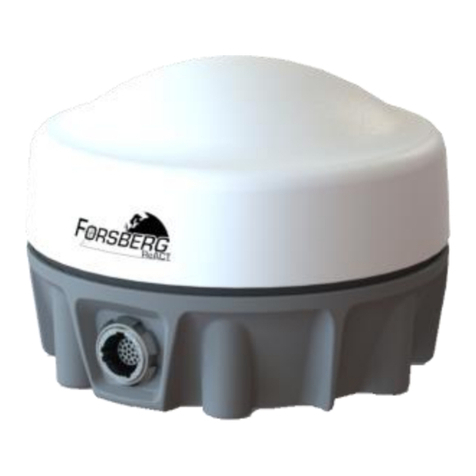
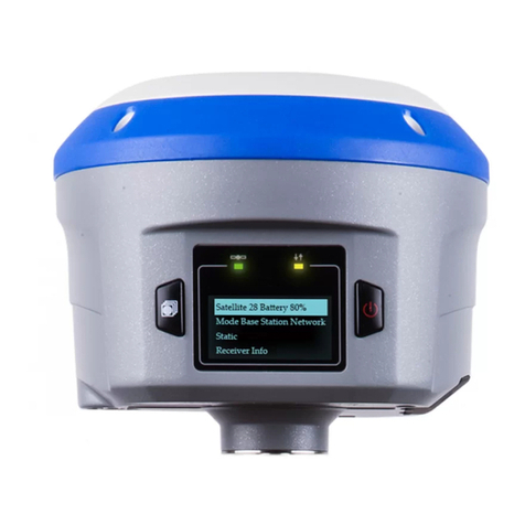
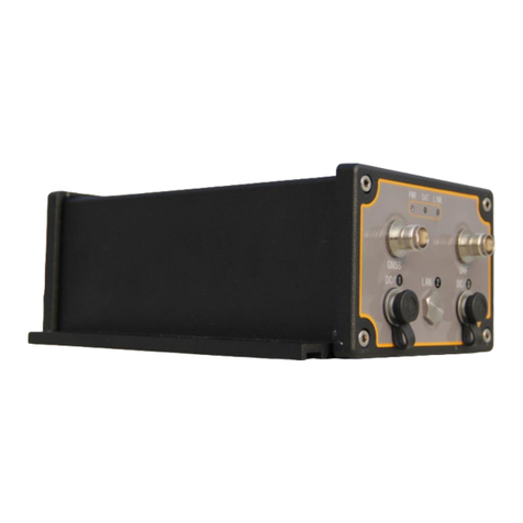
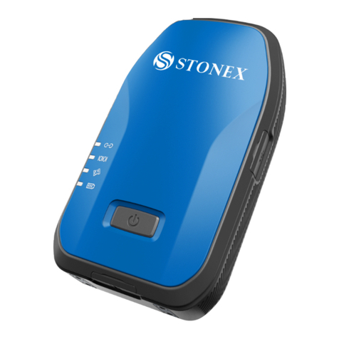
The ReACT+® Smart Antenna is a compact, rugged
enclosure including a high precision GPS and GNSS
Receiver and antenna. It offers the latest technology
for precision position, velocities, heading and
attitude by GNSS-alone or inertial navigation.
FEATURES AND BENEFITS:
555 Channels with Multi-constellation
tracking (GPS, GLONASS, BEIDOU, GALILEO,
SBAS, L-BAND).
Triple-frequency and multi-constellation
tracking increases position reliability and mitigates ionospheric effects.
Capable of centimetre-level accuracy using Terrastar C and RTK positioning. (Firmware activation
required)
PHYSICAL AND ELECTRICAL
Dimensions 174mm x 174mm x 93.2mm
Weight ~ 600 g
Input Voltage +9 to +36 VDC
Power Consumption < 4 W
MOUNTING
2 x Magnet
4 x M4 inserts [70.5mm / 2.78" Sq.]
PHASE CENTRE MEASUREMENT
The phase centre of the antenna is provided on the bottom of the ReACT+ system.
BOX CONTENTS:
The ReACT+ system, Part No. FRL01-0004 is provided with the following items.
1. ReACT+ System Enclosure. P/N: FRL04-000?
2. Fischer Connector Cable Plug. P/N: UP01Q11 M019S BK1 Z1ZA
3. Fischer Connector Sealing Boot. P/N: UB11 A1BK Ø3.9

A0111-09-004 QUICK START GUIDE
Page 2 v1.00
Forsberg Services Limited
www.forsbergservices.co.uk | info@forsbergservices.co.uk
Company Registration No: SC104949, Registered Office: Forsberg Services Ltd, 1 East Craibstone Street, Aberdeen, LA1 4XF
4. Quick start Guide Doc No: A0111-09-0005
5. ReACT+ Comms cable (Optional)
ADDITIONAL EQUIPMENT REQUIRED
The additional equipment listed below is needed for a basic setup:
•A Windows-based PC with an RS-232 DB-9 or USB port
•A standard 12 VDC power outlet
REACT+ COMMS CABLE
The ReACT+ comms cable provides access to all communication ports on the system.
Description
Fischer Part Number
ReACT+ Cable (5m long)
UP01L11 M019S BK1 Z1ZA
Pin
Signal
Description
Terminated to
1
COM3 TXD / USB_D-
GNSS COM3 RS 232
Or GNSS USB
Connector B pin 2 & D5 Pin 2
2
COM3 RXD / USB_D+
Connector B Pin 3 & D5 Pin 3
3
GNSS CAN High
GNSS CAN port
Connector C Pin 7
4
GNSS CAN Low
Connector C Pin 2
5
COM2 TXD
GNSS COM2
Connector D4 Pin 2
6
COM2 RXD
Connector D4 Pin 3
7
CONFIG TXD*
Com port configuration
Connector D3 Pin 2
8
CONFIG RXD*
Connector D3 Pin 3
9
NC
Reserved/ Not Connected
NC
10
NC
NC
11
GNSS PPS
GNSS PPS strobe
(E) un-terminated
12
GNSS EVENT2
GNSS Event In strobe
(E) un-terminated
13
GNSS VARF
GNSS Variable frequency
strobe
(E) un-terminated
14
COM1 TXD / TX+
Connector D-1 Pin 2

A0111-09-004 QUICK START GUIDE
Page 3 v1.00
Forsberg Services Limited
www.forsbergservices.co.uk | info@forsbergservices.co.uk
Company Registration No: SC104949, Registered Office: Forsberg Services Ltd, 1 East Craibstone Street, Aberdeen, LA1 4XF
15
COM1 TX-
GNSS COM1 (RS232 or
RS422)
Connector D-1 Pin 8
16
COM1 RXD / RX+
Connector D-1 Pin 3
17
COM1 RX-
Connector D-1 Pin 7
18
Power Return
Power
Connector F (Ring)
19
9-36V Power Input
Connector F (Tip)
Shield. Signal Ground
(E) un-terminated
Connector A , Shell
Connector B Pin 4
Connector C Pin 3
Connector D1 Pin 5
Connector D3 Pin 5
Connector D4 Pin 5
SETTING UP YOUR REACT+
Complete the steps below to connect and power your ReACT+
1. Connect the ReACT+ Comms cable to the ReACT+ Connector
2. Mount the ReACT+ on a secure, stable structure with an unobstructed view
of the sky.
3. Connect Connector D-1 (COM1) to the PC serial port DB-9 RS232 port.
4. Connect the PWR connector to the 12VDC power source
5. Turn on power to unit
CONNECTING TO THE REACT+
Connecting to the ReACT+ can be done through FSL’s NAVpak software or through a serial terminal program,
such as RealTerm or HyperTerminal.
The default connections parameters are:
BAUD RATE: 9600 DATA BITS: 8 PARITY: NONE STOP BITS: 1 FLOW CONTROL: NONE
CHECKING THE REACT+ POSITION IS VALID
Once connected to the ReACT+ the BESTPOS message can be used to check the receiver position and position
quality.
To obtain the Position from the ReACT enter:
LOG BESTPOSA ONCE
This will return an ASCII message showing the Best Position from the receiver. For details of the message
please refer to: OEM7 Family Firmware Manual
QUICK START CONFIGURING THE UNIT
The following commands will offer a reference for setting up the receiver, the full list are found in the OEM7
Family Firmware Manual.

A0111-09-004 QUICK START GUIDE
Page 4 v1.00
Forsberg Services Limited
www.forsbergservices.co.uk | info@forsbergservices.co.uk
Company Registration No: SC104949, Registered Office: Forsberg Services Ltd, 1 East Craibstone Street, Aberdeen, LA1 4XF
SAVING A CONFIGURATION
SAVECONFIG
This will save any configurations in use by the system to Non-volatile memory. The settings will be retained
through power cycles.
LOGGING POSITION
LOG BESTPOSA ONTIME 1 (LOGS BEST POSITION)
ENABLING SBAS
SBASCONTROL ENABLE AUTO
CONFIGURE AS A BASE STATION (RTCMV3 WITH GLONASS)
SERIALCONFIG COM2 9600 N 8 1 N ON (CORRECTIONS OUTPUT ON COM2)
INTERFACEMODE COM2 NONE RTCMV3 OFF
FIX POSITION LAT LON HGT (ENTER YOUR OWN LAT, LON, HGT)
LOG COM2 RTCM1002 ONTIME 1 (FOR L1 ONLY MODELS)
LOG COM2 RTCM1004 ONTIME 1 (FOR L1/L2 MODELS)
LOG COM2 RTCM1010 ONTIME 1 (FOR L1 ONLY MODELS)
LOG COM2 RTCM1012 ONTIME 1 (FOR L1/L2 MODELS)
LOG COM2 RTCM1006 ONTIME 10
LOG COM2 RTCM1033 ONTIME 10
LOG COM2 RTCM1019 ONTIME 120
LOG COM2 RTCM1020 ONTIME 120
SAVECONFIG
CONFIGURE AS A DGPS ROVER
INTERFACEMODE COM2 RTCMV3 NOVATEL OFF
CONFIGURE AS AN RTK ROVER (RTK FIRMWARE ACTIVATION REQUIRED)
INTERFACEMODE COM2 RTCMV3 NOVATEL OFF
RTKSOURCE AUTO ANY
CONFIGURE FOR PPP TERRASTAR CORRECTIONS
ASSIGNLBANDBEAM AUTO
In some cases an automatic configuration of the L-Band signal may not fit the application or area of operation.
To manually configure the unit refer to APN061 NovAtel CORRECT with TerraStar
FACTORY RESET
To reset the system enter:
FRESET

A0111-09-004 QUICK START GUIDE
Page 5 v1.00
Forsberg Services Limited
www.forsbergservices.co.uk | info@forsbergservices.co.uk
Company Registration No: SC104949, Registered Office: Forsberg Services Ltd, 1 East Craibstone Street, Aberdeen, LA1 4XF
This will wipe all settings and return the unit to its default configuration.
CONNECTING TO NAVPAK
Forsberg’s NAVpak software suite provides real-time and post-processing quality control for a range of GNSS
receivers. The data is displayed in real-time and logged-to-file for monitoring navigational accuracy and the
receivers’ Built-In-Test. The graphical design of time-windowed graphs and sky plots simplifies the examination
of logged data and provides an advanced quality diagnosis tool.
NAVpak is offered as a free product but with premium features. The premium features are activated through a
Sentinel Key Dongle.
INSTALLATION
If you have purchased NAVpak Premium ensure that the
provided Sentinel Key has been connected to a spare USB
port. The drivers should install automatically.
To install NAVpak select and run the “setup.exe” file that is
provided on the NAVpak CD.
Follow on screen instructions to install the software.
CONNECT TO A RECEIVER
LIVE CONNECTION
For NAVpak to connect to a receiver a serial connection is required. This can be through a PC serial port or via
USB virtual serial ports.
Connect to a live receiver by selecting “Live Connection”
Enter a device name to identify the connected system and select the PC com port.
Select the Type of connection as either “NovAtel” when connected to a NovAtel GNSS system or
“NMEA” when connected to a device capable of outputting NMEA data.
Select “Create Device” to establish a connection
OPEN FROM FILE
NAVpak can open previously recorded data or import data from another device.
Select “Playback from File”
Browse for the file to be used on your PC, or select “Recent Files”
Select “Open Session”

A0111-09-004 QUICK START GUIDE
Page 6 v1.00
Forsberg Services Limited
www.forsbergservices.co.uk | info@forsbergservices.co.uk
Company Registration No: SC104949, Registered Office: Forsberg Services Ltd, 1 East Craibstone Street, Aberdeen, LA1 4XF
NAVPAK USER INTERFACE
The NAVpak user interface is described by the following sections:
Panels: Providing controls to open data panels in the work frame.
Tools: Providing access to Wizards, specialised tools and configuration controls.
Playback controls: Provides playback controls when applicable.
Status: GNSS quality, software and hardware alarms and alerts.
Active connections: To add and remove receiver connections or add data files.
Work Frame: Data panels are displayed in the work frame and can be moved around the screen as required.

A0111-09-004 QUICK START GUIDE
Page 7 v1.00
Forsberg Services Limited
www.forsbergservices.co.uk | info@forsbergservices.co.uk
Company Registration No: SC104949, Registered Office: Forsberg Services Ltd, 1 East Craibstone Street, Aberdeen, LA1 4XF
DATA PANELS
The tool bar at the top of the window provides access to all data panels and once clicked the selected panel will display
within the NAVpak work frame.
Panels
Position information
Displays Latitude, Longitude, Height and corresponding quality information.
Status Summary
Traffic light indicating the status of the connected device and active alarms
Sky plot
Displays GPS, GLONASS and SBAS Satellite sky position, signal strength and
health
Carrier to Noise
Displays GPS, GLONASS and SBAS Satellite signal strength in a bar chart.
Velocity information
Displays velocity data and corresponding quality information.
Inertial information
Displays pitch, roll and attitude (when operating with an IMU)
Data graphing - Custom
Premium NAVpak
The ability to graph data live or from a recorded file
Data graphing - Preset
Premium NAVpak
The ability to graph data live or from a recorded file
Command terminal
Send commands to the receiver for advanced configuration control
Mark Messages
If a pulse is received on the Event in port, displays the marked position.
LBand
Displays LBand tracking status, information and alarms.
Heading
If a NovAtel ALIGN receiver is attached the heading information is displayed
here.
Receiver logs
Displays the configuration of the receiver
NAVpak settings:
Adjust NAVpak settings
Tools
Inertial Wizard
Create the configuration file required for an Inertial system set-up

A0111-09-004 QUICK START GUIDE
Page 8 v1.00
Forsberg Services Limited
www.forsbergservices.co.uk | info@forsbergservices.co.uk
Company Registration No: SC104949, Registered Office: Forsberg Services Ltd, 1 East Craibstone Street, Aberdeen, LA1 4XF
EDGE-COM Wizard
Create custom data messages and configure EDGE ports
(Requires connection to EDGE port)
EDGE-CAN Wizard
Create custom CAN frames for output over the CAN port
(Requires connection to EDGE port)
NAVtrak
NAVtrak is an application for setting and navigating to Waypoints
Using NAVtrak will stop NAVpak logs and open the NAVtrak application
Status
Status alarms
Displays receiver status and built in test alarms
History alarms
Displays a history of all alarms that have been triggered
Table of contents
Other Forsberg Receiver manuals
