Fortec Star iBASE IBR210 User manual

The information contained in this document has been carefully researched and is, to the best of our
knowledge, accurate. However, we assume no liability for any product failures or damages, immediate or
consequential, resulting from the use of the information provided herein. Our products are not intended for
use in systems in which failures of product could result in personal injury. All trademarks mentioned herein
are property of their respective owners. All specifications are subject to change without notice.
Manual
iBASE
IBR210
3,5”Low Power Single-Board Computer with NXP i.MX 8M Dual/Quad Cortex-A53 ARM® Processor

IBR210
3.5” ARM-based SBC
With NXP Cortex™ A53 Quad/Dual i.MX8M
User’s Manual
Version 0.2
(Sep. 2019)

ii
IBR210 User’s Manual
Copyright
© 2018 IBASE Technology, Inc. All rights reserved.
No part of this publication may be reproduced, copied, stored in a retrieval
system, translated into any language or transmitted in any form or by any
means, electronic, mechanical, photocopying, or otherwise, without the prior
written consent of IBASE Technology, Inc. (hereinafter referred to as
“IBASE”).
Disclaimer
IBASE reserves the right to make changes and improvements to the
products described in this document without prior notice. Every effort has
been made to ensure the information in the document is correct; however,
IBASE does not guarantee this document is error-free.
IBASE assumes no liability for incidental or consequential damages arising
from misapplication or inability to use the product or the information
contained herein, nor for any infringements of rights of third parties, which
may result from its use.
Trademarks
All the trademarks, registrations and brands mentioned herein are used for
identification purposes only and may be trademarks and/or registered
trademarks of their respective owners.

IBR210 User’s Manual
iii
Compliance
In a domestic environment, this product may cause radio interference in
which case users may be required to take adequate measures.
This product has been tested and found to comply with the limits for a Class
B device, pursuant to Part 15 of the FCC Rules. These limits are designed to
provide reasonable protection against harmful interference in a residential
installation. This equipment generates, uses and can radiate radio frequency
energy and, if not installed and used in accordance with manufacturer’s
instructions, may cause harmful interference to radio communications.
WEEE
This product must not be disposed of as normal household
waste, in accordance with the EU directive of for waste
electrical and electronic equipment (WEEE - 2012/19/EU).
Instead, it should be disposed of by returning it to a
municipal recycling collection point. Check local
regulations for disposal of electronic products.
Green IBASE
This product is compliant with the current RoHS
restrictions and prohibits use of the following substances in
concentrations exceeding 0.1% by weight (1000 ppm)
except for cadmium, limited to 0.01% by weight (100 ppm).
• Lead (Pb)
• Mercury (Hg)
• Cadmium (Cd)
• Hexavalent chromium (Cr6+)
• Polybrominated biphenyls (PBB)
• Polybrominated diphenyl ether (PBDE)
iv
IBR210 User’s Manual
Important Safety Information
Carefully read the precautions before using the board.
Environmental conditions:
• Use this product in environments with ambient temperatures between
0˚C and 70˚C. (Industrial grade: -40° C and 85° C)
• Do not leave this product in an environment where the storage
temperature may be below -40° C or above 85° C. To prevent from
damages, the product must be used in a controlled environment.
Care for your IBASE products:
• Before cleaning the PCB, unplug all cables and remove the battery.
• Clean the PCB with a circuit board cleaner or degreaser, or use cotton
swabs and alcohol.
• Vacuum the dust with a computer vacuum cleaner to prevent the fan
from being clogged.
WARNING
Attention during use:
• Do not use this product near water.
• Do not spill water or any other liquids on this product.
• Do not place heavy objects on the top of this product.
Anti-static precautions
• Wear an anti-static wrist strap to avoid electrostatic discharge.
• Place the PCB on an anti-static kit or mat.
• Hold the edges of PCB when handling.
• Touch the edges of non-metallic components of the product instead of
the surface of the PCB.
• Ground yourself by touching a grounded conductor or a grounded bit of
metal frequently to discharge any static.
CAUTION
Danger of explosion if the internal lithium-ion battery is replaced by an
incorrect type. Replace only with the same or equivalent type recommended
by the manufacturer. Dispose of used batteries according to the
manufacturer’s instructions or recycle them at a local recycling facility or
battery collection point.

IBR210 User’s Manual
v
Warranty Policy
• IBASE standard products:
24-month (2-year) warranty from the date of shipment. If the date of
shipment cannot be ascertained, the product serial numbers can be
used to determine the approximate shipping date.
• 3rd-party parts:
12-month (1-year) warranty from delivery for the 3rd-party parts that are
not manufactured by IBASE, such as CPU, CPU cooler, memory,
storage devices, power adapter, panel and touchscreen.
* PRODUCTS, HOWEVER, THAT FAIL DUE TO MISUSE, ACCIDENT,
IMPROPER INSTALLATION OR UNAUTHORIZED REPAIR SHALL
BE TREATED AS OUT OF WARRANTY AND CUSTOMERS SHALL
BE BILLED FOR REPAIR AND SHIPPING CHARGES.
Technical Support & Services
1. Visit the IBASE website at www.ibase.com.tw to find the latest
information about the product.
2. If you need any further assistance from your distributor or sales
representative, prepare the following information of your product and
elaborate upon the problem.
• Product model name
• Product serial number
• Detailed description of the problem
• The error messages in text or in screenshots if there is any
• The arrangement of the peripherals
• Software in use (such as OS and application software, including the
version numbers)
3. If repair service is required, you can download the RMA form at
http://www.ibase.com.tw/english/Supports/RMAService/. Fill out the
form and contact your distributor or sales representative.

vi
IBR210 User’s Manual
Table of Contents
Compliance .................................................................................... iii
Important Safety Information ....................................................... iv
Warranty Policy .............................................................................. v
Technical Support & Services ....................................................... v
Chapter 1 General Information ............................................ 1
1.1 Introduction ............................................................................................ 2
1.2 Features ................................................................................................. 2
1.3 Packing List ........................................................................................... 3
1.4 Specifications ......................................................................................... 4
1.5 Overview ................................................................................................ 6
1.6 Dimensions ............................................................................................ 7
Chapter 2 Hardware Configuration .......................................... 9
2.1 Mini-PCIe & M.2 Card Installation ........................................................ 10
2.2 Setting the Jumpers ............................................................................. 11
2.3 Jumper & Connector Locations on IBR210 ......................................... 12
2.4 Jumpers Quick Reference ................................................................... 13
2.4.1 LVDS Power Setting (P16) ..................................................... 13
2.4.2 LVDS Backlight Power Setting (P15) ..................................... 14
2.5 Connectors Quick Reference ............................................................... 15
2.5.1 RTC Lithium Cell Connector (P2) ........................................... 16
2.5.2 COM RS-232/422/485 Selection (SW3) ................................. 16
2.5.3 COM RS-232/422/485 Port (P20) .......................................... 17
2.5.4 LVDS Display Connector (P13, P14) ..................................... 18
2.5.5 COM RS232 Connector (P19) ................................................ 19
2.5.6 LVDS Backlight Control Connector (P18) .............................. 20
2.5.7 Audio Line-In & Line-Out Connector (P9) ............................... 20
2.5.8 USB Hub Connector (P7) ....................................................... 21
2.5.9 Digital I/O (GPIO) Connector (P24) ........................................ 22
2.5.10 MIPI-CSI Connector (P10, P26) ............................................. 23
2.5.11 MIPI-DSI Connector (P12) ..................................................... 24
2.5.12 I2C Connector (P17) ............................................................... 25
Chapter 3 Software Setup .................................................. 27

IBR210 User’s Manual
vii
3.1 Make a Recovery SD Card ................................................................. 28
3.2 Display Parameter Setting in Kernel ................................................... 29
Chapter 4 BSP Source Guide ............................................. 30
4.1 Preparation ......................................................................................... 31
4.2 Building BSP release .......................................................................... 31
Appendix ....................................................................................... 32
A. How to Use GPIO in Linux .................................................................. 33
B. How to Use Watchdog in Linux ........................................................... 33
C. eMMC Test ......................................................................................... 34
D. USB (flash disk) Test .......................................................................... 35
E. SD Card Test ...................................................................................... 36
F. RS-232 Test ........................................................................................ 37
G. RS-485 Test ........................................................................................ 38
H. Audio Test ........................................................................................... 38
I. Ethernet Test ...................................................................................... 39
J. LVDS Test ........................................................................................... 40
K. HDMI Test ........................................................................................... 41
L. 3G Test ............................................................................................... 42
M. Onboard Connector Types .................................................................. 43

viii
IBR210 User’s Manual
This page is intentionally left blank.

1
Chapter 1
General Information
The information provided in this chapter includes:
• Features
• Packing List
• Specifications
• Block Diagram
• Board Overview
• Board Dimensions
2
IBR210 User’s Manual
1.1 Introduction
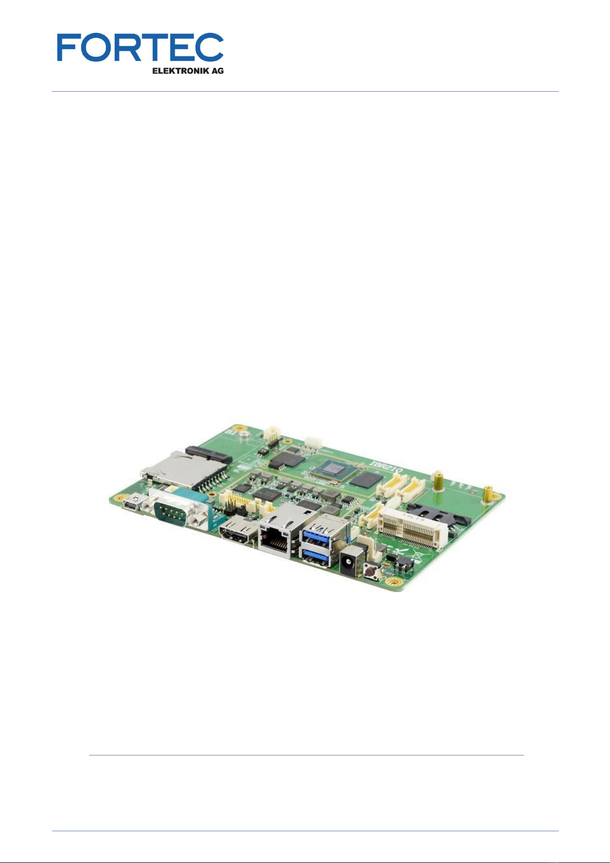
IBR210 is a 3.5" Disk-Size SBC w/ ARM Base NXP i.MX6 Cortex-A53
1.5/1.3 GHz CPU. The device offers 2D, 3D graphics and multimedia
accelerations, while also supporting numerous peripherals, including
RS-232/422/485, COM, GPIO, USB3.0/2.0, USB OTG, LAN and audio
interfaces. For the display, it also supports 1 HDMI for a 4K display or FHD
Dual-channel LVDS, for the wireless connectivity. Other features are an M.2
Key-E, type 2230 and mini-PCIe expansion that are well suited for industrial
applications.
Photo of IBR210
1.2 Features
• With NXP CortexTM-A53/CortexTM-M4, i.MX 8M Dual/Quad 1.5GHz
Processor
• Supports 4K HDMI, or dual channel FHD LVDS
• Supports 3GB LPDDR4, 8/16/32/64GB eMMC and SD socket
• Supports embedded I/O for COM, GPIO, USB3.0, USB-OTG, Audio
and Ethernet
• M.2 E2230 & mini-PCIe with the SIM socket for wireless connectivity
• Supports M.2 Key-E (2230) and mini-PCI-E with SIM socket for
wireless/4G/LTE connectivity

General Information
IBR210 User’s Manual
3
1
1.3 Packing List
Your IBR210 package should include the items listed below. If any of the
items below is missing, contact the distributor or dealer from whom you
purchased the product.
• IBR210 3.5” SBC x 1
• This User Manual x 1
4
IBR210 User’s Manual
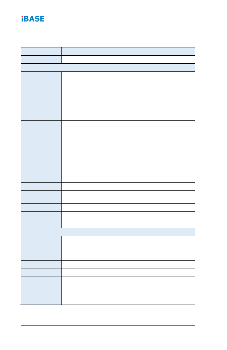
1.4 Specifications
Product Name
IBR210
Form Factor
3.5” SBC
System
Operating
System
• Yocto v2.5 (Kernel 4.14.62)
• Android 9 (Kernel 4.14.62)
CPU Type
NXP Cortex™ A53 i.MX8M Quad/Dual Core SoC
CPU Speed
Up to 1.5 GHz
Memory
• System memory: 3 GB LPDDR4
• Data Memory: 8/16 GB eMMC
Video Codec
• 4Kp60 HEVC/H.265 main, and main 10 decoder
• 4Kp60 VP9 decoder
• 4Kp30 AVC/H.264 decoder
• 1080p60 MPEG-2, MPEG-4p2, VC-1, VP8, RV9, AVS,
MJPEG, H.263 decoder
Touch
USB headers
RTC
IDT 1337AGDVGI8
Wireless
Wi-Fi / BT / 3G / LTE module (Optional)
Power Supply
12-24VDC-In Jack and Internal header
Watchdog
Timer
Yes (256 segments, 0, 1, 2…128 secs)
Dimensions
146 x 102 mm (5.74” x 4.02”)
RoHS
Yes
Certification
CE, FCC Class B
I/O Ports
DC Jack
l 1 x 12-24V DC jack
Display
• Dual Channel LVDS (FHD) or 4-lane MIPI-DSI
• HDMI V2.0a, support HDCP2.2 and HDCP1.4
Camera
• 2x MIPI-CSI (2*10 pin header)
LAN
l 1 x RJ45 GbE LAN
USB
• 2 x USB 3.0 Type A
• 1 x USB OTG via mini-USB Type B
• 2 x USB 3.0 internal port

General Information
IBR210 User’s Manual
5
1
Serial
• 1x I2C header
• 1x 2-wire RS232 header (for Debug Console Port)
• 2x 2-wire RS232 header
Audio
l 1 x Audio header (Line-in and Line-out)
Digital IO
l 8x GPIO (2*5 pin header 1.0mm)
Expansion
Slots
• 1x M.2 Key-E (2230) w/ USB, SDIO, UART, PCI-E
• 1x Mini PCI-E w/ SIM socket
Environment
Operating
Temperature
• 0 ~ 70 °C (32 ~ 158 °F)
• -40 ~ 85 °C (-40 ~ 185 °F)
Relative
Humidity
10 ~ 90 %, non-condensing
All specifications are subject to change without prior notice.

6
IBR210 User’s Manual
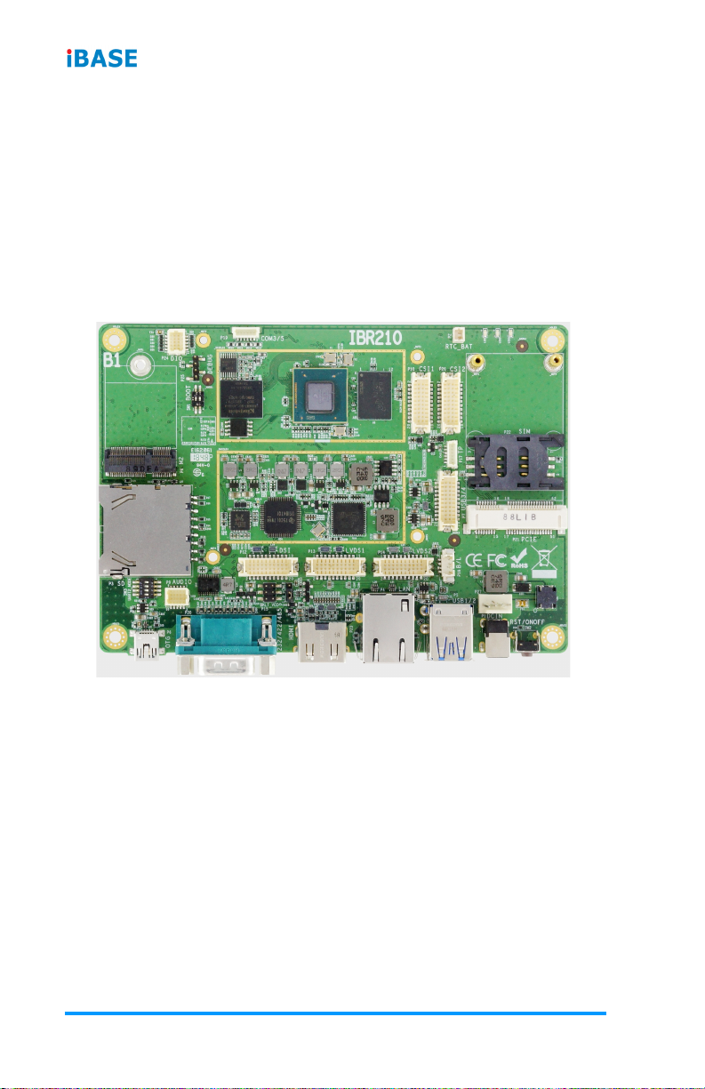
1.5 Overview
Top View
*The photos above are for reference only. Some minor components may differ.
I/O View

General Information
IBR210 User’s Manual
7
1
1.6 Dimensions
Unit: mm

8
IBR210 User’s Manual
IBR210 Reference Heat Sink

9
Chapter 2
Hardware Configuration
This section provides information on jumper settings and
connectors on the IBR210 in order to set up a workable system.
The topics covered are:
• M.2 card Installation
• Jumper and connector locations
• Jumper settings and information of connectors
10
IBR210 User’s Manual
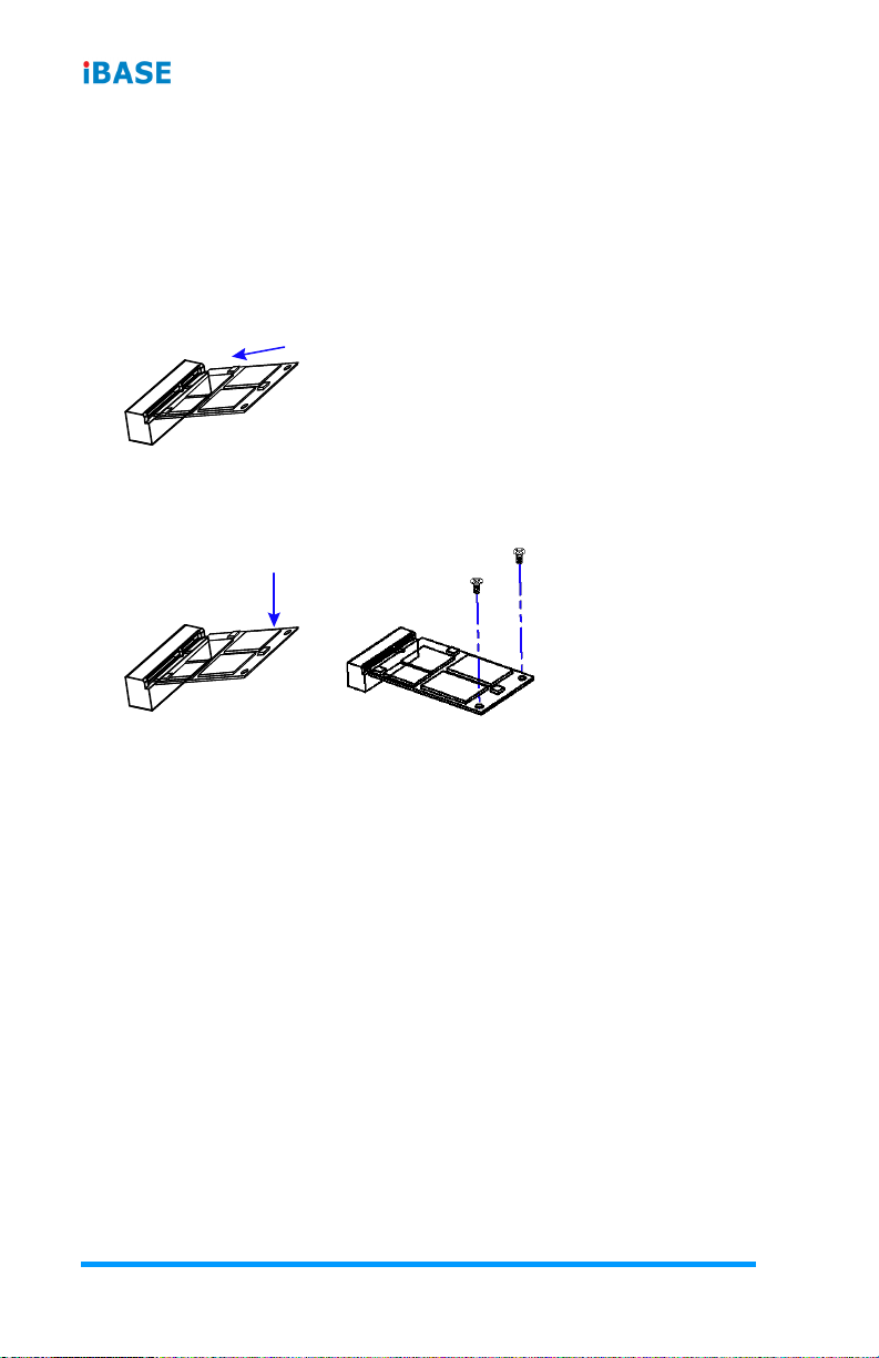
2.1 Mini-PCIe & M.2 Card Installation
To install the mini-PCIe and M.2 cards, perform the following steps.
1. Locate the mini-PCIe slot, align the key of the mini-PCIe card to the
interface, and insert the card slantwise.
(Insert the M.2 card in the same way.)
2. Push the mini-PCIe card down and fix it with 2 flat head screws.
(Fix the M.2 card with one screw.)
Table of contents
Other Fortec Star Motherboard manuals

Fortec Star
Fortec Star CM1-BT1 User manual

Fortec Star
Fortec Star ADVANTECH AIMB-229 User manual

Fortec Star
Fortec Star GIGAIPC QBiP-8565A User manual

Fortec Star
Fortec Star iBase MBB-1000 User manual

Fortec Star
Fortec Star iBASE MB995 User manual

Fortec Star
Fortec Star congatec conga-IC175 User manual

Fortec Star
Fortec Star Advantech AIMB-586 User manual

Fortec Star
Fortec Star conga-PA3 Pico-ITX SBC User manual


