Fortec Star CM1-BT1 User manual

The information contained in this document has been carefully researched and is, to the best
of our knowledge, accurate. However, we assume no liability for any product failures or
damages, immediate or consequential, resulting from the use of the information provided
herein. Our products are not intended for use in systems in which failures of product could
result in personal injury. All trademarks mentioned herein are property of their respective
owners. All specifications are subject to change without notice.
Manual
CMx-BTx
CM1-BT1 / CM2-BT2
CM3-BT2 / CM3-BT4
ADLINK Technology
Our company network supports you worldwide with offices in Germany, Austria,
Switzerland, Great Britain and the USA. For more information please contact:
FORTEC Elektronik AG
Hauptniederlassung
Lechwiesenstr. 9
86899 Landsberg am Lech
Telefon: +49 (0) 8191 91172-0
Telefax: +49 (0) 8191 21770
E-Mail: [email protected]
Internet: www.fortecag.de
FORTEC Elektronik AG
Büro West
Hohenstaufenring 55
50674 Köln
Telefon: +49 (0) 221 272 273-0
Telefax: +49 (0) 221 272 273-10
E-Mail: [email protected]
Internet: www.fortecag.de
FORTEC Elektronik AG
Büro Wien
Nuschinggasse 12
A-1230 Wien
Telefon: +43 1 8673492-0
Telefax: +43 1 8673492-26
E-Mail: [email protected]
Internet: www.fortec.at
ALTRAC AG
(Tochter der FORTEC):
Bahnhofstraße 3
CH-5436 Würenlos
Telefon: +41 (0) 44 7446111
Telefax: +41 (0) 44 7446161
E-Mail: [email protected]
Internet: www.altrac.ch

Advance Technologies. Automate the World.
CMx-BTx
PC/ 104-Plus Single Board Computer
Technical Manual
P/N 50-1Z161-1020
Rev 3.00

ii
Technical Manual CMx-BTx
Document: 50-1Z161-1020
Copyright © 2015, 2016 ADLINK Technology, All rights reserved
Trademarks
MS-DOS, Windows, Windows 95, Windows 98, Windows NT and Windows XP are trade-
marks of Microsoft Corporation. PS/2 is a trademark of International Business Machines, Inc.
Intel and Solid State Drive are trademarks of Intel Corporation. PC/104 is a registered trade-
mark of the PC/104 Consortium. All other trademarks appearing in this document are the
property of their respective owners.
Disclaimer
Information in this document is provided in connection with ADLINK products. No license,
express or implied, by estoppel or otherwise, to any intellectual property rights is granted by
this document. Except as provided in ADLINK´s Terms and Conditions of Sale for such prod-
ucts, ADLINK assumes no liability whatsoever, and ADLINK disclaims any express or implied
warranty, relating to sale and/or use of ADLINK products including liability or warranties relat-
ing to fitness for a particular purpose, merchantability, or infringement of any patent, copy-
right or other intellectual property right. If you intend to use ADLINK products in or as
medical devices, you are solely responsible for all required regulatory compliance, including,
without limitation, Title 21 of the CFR (US), Directive 2007/47/EC (EU), and ISO 13485 &
14971, if any. ADLINK may make changes to specifications and product descriptions at any
time, without notice.
Environmental Responsibility
ADLINK is committed to fulfill its social responsibility to global environmental preservation
through compliance with the European Union's Restriction of Hazardous Substances (RoHS)
directive and Waste Electrical and Electronic Equipment (WEEE) directive. Environmental
protection is a top priority for ADLINK. We have enforced measures to ensure that our prod-
ucts, manufacturing processes, components, and raw materials have as little impact on the
environment as possible. When products are at their end of life, our customers are encour-
aged to dispose of them in accordance with the product disposal and/or recovery programs
prescribed by their nation or company.

iii
CMx-BTx
Important Safety Instructions
For user safety, please read and follow all Instructions, WARNINGs, CAUTIONs, and
NOTEs marked in this manual and on the associated equipment before handling/operating
the equipment.
Read these safety instructions carefully.
Keep this manual for future reference.
Read the specifications section of this manual for detailed information on the operating
environment of this equipment.
Turn off power and unplug any power cords/cables when installing/mounting or un-install-
ing/removing equipment.
To avoid electrical shock and/or damage to equipment:
Keep equipment away from water or liquid sources;
Keep equipment away from high heat or high humidity;
Keep equipment properly ventilated (do not block or cover ventilation openings);
Make sure to use recommended voltage and power source settings;
Always install and operate equipment near an easily accessible electrical socket-
outlet;
Secure the power cord (do not place any object on/over the power cord);
Only install/attach and operate equipment on stable surfaces and/or recommended
mountings; and,
If the equipment will not be used for long periods of time, turn off the power source and
unplug the equipment.

iv

v
CMx-BTx
Table of Content
1 Introduction...................................................................................................................... 1
1.1 Overview ................................................................................................................................ 1
1.2 Features................................................................................................................................. 1
1.3 Block Diagram........................................................................................................................ 2
1.4 Ordering Information .............................................................................................................. 3
1.5 Specifications......................................................................................................................... 4
2 Getting Started................................................................................................................. 7
2.1 Header and Connector Locations .......................................................................................... 7
2.2 Mechanical Dimensions ....................................................................................................... 11
2.3 LED Indicators ..................................................................................................................... 12
2.4 Hardware Setup ................................................................................................................... 13
3 Module Description ....................................................................................................... 15
3.1 SoC (System on a Chip) ...................................................................................................... 15
3.1.1 Processor Core.................................................................. .............................................15
3.1.2 Memory Controller ............................................................. .............................................15
3.1.3 Graphics Engine ................................................................ .............................................15
3.1.4 Image Signal Processor..................................................... .............................................16
3.1.5 Power Management........................................................... .............................................16
3.1.6 PCI Express....................................................................... .............................................16
3.1.7 SATA Controller................................................................. .............................................16
3.1.8 USB xHCI Controller.......................................................... .............................................16
3.1.9 USB 2.0 EHCI Controller ................................................... .............................................16
3.1.10HD-Audio Controller........................................................... .............................................16
3.1.11Intel® Trusted Execution Engine (Intel® TXE) .................. .............................................17
3.1.12Platform Control Unit (PCU) .............................................. .............................................17
3.2 VGA Interface ...................................................................................................................... 17
3.3 LVDS Interface..................................................................................................................... 18
3.4 LVDS Backlight.................................................................................................................... 20
3.4.1 Selecting Panel and Backlight voltage............................... .............................................21
3.5 Ethernet Controllers ............................................................................................................. 21
3.6 USB Ports ............................................................................................................................ 23
3.7 On-Board Power Supply ...................................................................................................... 24
3.8 System Panel....................................................................................................................... 25
3.9 Serial Ports .......................................................................................................................... 26
3.10 Setting RS485/RS422 Termination...................................................................................... 28
3.11 mini-PCIe Interface .............................................................................................................. 29
3.12 PCI-104 Bus Interface.......................................................................................................... 30
3.13 PC/104 Bus Interface........................................................................................................... 32
3.14 Audio Interface..................................................................................................................... 34
3.15 BMC Service Connector ...................................................................................................... 35
3.16 User GPIO Interface ............................................................................................................ 37

vi
3.17 FAN Interface ......................................................................... ........................................... 38
3.18 Battery Interface.................................................................................................................. 38
4 Using the Module .......................................................................................................... 39
4.1 SEMA functions................................................................................................................... 39
4.1.1 Board specific SEMA functions .......................................... ............................................ 40
4.2 Watchdog Timer .................................................................................................................. 41
4.3 Setting SW4 BIOS Control Switch....................................................................................... 42
4.4 BIOS Setup Utility Screens ................................................................................................. 43
4.4.1 Main ................................................................................... ............................................ 43
4.4.2 Main > System Management ............................................. ............................................ 44
4.4.3 Main > System Management > Board Information............. ............................................ 44
4.4.4 Main > System Management > Temperatures and Fan Speed ...................................... 45
4.4.5 Main > System Management > Power Consumption......... ............................................ 45
4.4.6 Main > System Management > Runtime Statistics ............ ............................................ 46
4.4.7 Main > System Management > Flags ................................ ............................................ 46
4.4.8 Main > System Management > Power Up ......................... ............................................ 47
4.4.9 Main > System Management > LVDS Backlight ................ ............................................ 47
4.4.10Main > System Management > Smart Fan ........................ ............................................ 48
4.4.11Advanced ........................................................................... ............................................ 48
4.4.12Advanced > CPU Configuration ......................................... ............................................ 49
4.4.13Advanced > CPU Configuration > Socket 0 CPU Information ........................................ 49
4.4.14Advanced > CPU Configuration > CPU Thermal Configuration...................................... 50
4.4.15Advanced > CPU Configuration > PPM Configuration....... ............................................ 50
4.4.16Advanced > Graphics Configuration .................................. ............................................ 51
4.4.17Advanced > Graphics Configuration > Intel IGD Configuration....................................... 51
4.4.18Advanced > Graphics Configuration > Graphics Power Management Control ............... 52
4.4.19Advanced > Graphics Configuration > LCD Control .......... ............................................ 52
4.4.20Advanced > SATA Configuration ....................................... ............................................ 53
4.4.21Advanced > USB Configuration ......................................... ............................................ 53
4.4.22Advanced > USB Configuration > USB Configuration ....... ............................................ 54
4.4.23Advanced > SDIO Configuration ........................................ ............................................ 54
4.4.24Advanced > Network Configuration.................................... ............................................ 55
4.4.25Advanced > Audio Configuration ....................................... ............................................ 55
4.4.26Advanced > PCI/PCIe Configuration.................................. ............................................ 56
4.4.27Advanced > PCI/PCIe Configuration > PCIe Chipset Settings ....................................... 56
4.4.28Advanced > PCI/PCIe Configuration > PCI Subsystem Settings.................................... 57
4.4.29Advanced > PCI/PCIe Configuration > PCI Subsystem Settings >
PCI Express Settings .................................................... ............................................ 57
4.4.30Advanced > CI/PCIe Configuration > PCI Subsystem Settings > PCI Express Gen 2 Set-
tings .............................................................................. ............................................ 58
4.4.31Advanced > Baytrail Features Configuration...................... ............................................ 58
4.4.32Advanced > ACPI Settings................................................. ............................................ 59
4.4.33Advanced > Serial Port Console Redirection ..................... ............................................ 59
4.4.34Advanced > Serial Port Console Redirection > Console Redirection Settings ............... 60

vii
CMx-BTx
4.4.35Advanced > Thermal Configuration ................................... ............................................ 60
4.4.36Advanced > Security Configuration .................................................................................61
4.4.37Advanced > Miscellaneous ..............................................................................................61
4.4.38Advanced > NCT5104D Super IO Configuration .............................................................62
4.4.39Advanced > NCT5104D Super IO Configuration > Serial Port 1 Configuration...............62
4.4.40Advanced > NCT5104D Super IO Configuration > Serial Port 2 Configuration...............63
4.4.41Advanced > NCT5104D Super IO Configuration > Serial Port 3 Configuration...............63
4.4.42Advanced > NCT5104D Super IO Configuration Serial Port 4 Configuration..................64
4.4.43Advanced > Ethernet Controls.........................................................................................64
4.4.44Advanced > Mini-PCIe-slot function.................................................................................65
4.4.45Advanced > USB Controls ...............................................................................................65
4.4.46Advanced > Intel® I210 Gigabit Network Connection – 00:20:9D:….. ............................66
4.4.47Advanced > Intel® I210 Gigabit Network Connection – 00:20:9D:….. >
NIC Configuration .......................................................................................................66
4.4.48Security............................................................................................................................67
4.4.49Boot .................................................................................................................................67
4.4.50Boot > CSM Configuration...............................................................................................68
4.4.51Boot > Delete Boot Option ...............................................................................................68
4.4.52Save & Exit ......................................................................................................................69
4.5 Temperature Sensors ............................................................. ............................................ 69
4.6 Real Time Clock (RTC) .......................................................... ............................................ 69
4.7 Memory Address Map............................................................. ............................................ 70
4.8 I/O Address Map ..................................................................... ............................................ 73
4.8.1 PCI Configuration Registers ............................................................................................74
4.9 IO Register Maps .................................................................... ............................................ 76
4.9.1 CMOS Memory and RTC Registers ................................................................................76
4.10 Interrupts................................................................................. ............................................ 77
4.10.1SERIRQ Interrupt Mapping..............................................................................................77
4.11 Contact Information................................................................. ............................................ 78
4.11.1Additional Information ......................................................................................................80
4.11.2Getting Help.....................................................................................................................80
4.11.3Returning Products for Repair .........................................................................................80
4.11.4Revision History...............................................................................................................80

viii

Introduction 1
CMx-BTx
1 Introduction
1.1 Overview
The CMx-BTx is a PC/104-based, Single Board Computer (SBC), fully compliant with the
PCI-104 Specification, Version 1.1 and partially compliant with the PC/104 Specification, Ver-
sion 2.6. PC/104 SBCs are very compact and highly integrated computers. This SBC features
the 22nm, Intel®Bay Trail SoC.
The board provides a DDR3L SO-DIMM socket, a PC/104 connector, a PCI-104 connector, up
to four USB 2.0 ports (with one port routed to mini-PCIe slot), up to two Gigabit Ethernet ports,
up to two SATA 3 Gb/s ports, one dedicated HD-Audio panel connector, one VGA port, one
LVDS port, up to four COM ports, one mini-PCIe slot (including one USB 2.0 port).
The CMx-BTx can be run with only 5 volts and is capable of running operating systems like
DOS, Windows 7/8 in either 32-bit or 64-bit configuration, Linux, VxWorks, and others.
Another feature included on the board is a fail safe BIOS that enables the user to start the mod-
ule even if the original BIOS is corrupted.
1.2 Features
SoC
Intel® Bay Trail I/M/D with inte-
grated Graphics
Bay Trail-I Premium (E3845)
Bay Trail-I Med (E3825)
Bay Trail-I Entry (E3815)
Main Memory
Single channel 64bit DDR3L
1067 MT/s and 1333 MT/s
Non-ECC, unbuffered DDR3L
SO-DIMM up to 4 GB
Expansion slots
1x mini-PCIe with mSATA and
USB capability (3.3V I/O)
1x 16-bit PC/104 without DMA
and no bus mastering capability
1x 32-bit PCI-104
Interfaces
2x Ethernet, 1GBit
2x SATA 3Gb/s
4x USB 2.0 (one routed to
mini-PCIe slot)
4x RS232/485/422
5.1 channel HD-Audio (analog
& SPDIF)
1x VGA
1x 18/24 Bit LVDS for displays
8x User GPIO
System panel connector for
power and reset button cable,
watchdog out, speaker and
HDD-LED
Other configurations are possible. Please contact your local ADLINK
Technology representative to discuss requirements.

2Introduction
1.3 Block Diagram
Figure 1-1: Functional Block Diagram
Intel
BayTrail-I
SoC
E3845 (4C)
E3825 (2C)
E3815 (1C)
PCI
LPC
I210IT
Ethernet
(option)
PCIe[1] x1
Optional:
2nd GbE
LVDS Inver ter CTRL
PCI-104
I210IT
Ethernet
1st GbE
LVDS
single/dual channel 18/24-bit
PTN3460
eDP to LVDS
DDI 0
(eDP 1.3 / 2 lanes)
DDR3L-1333
SO-DIMM socket
Inverter
(Backlight)
PCIe[2] x1
BIOS 2
BIOS 1 BMC / SEMA
DIAG
LM 73
Power Supply
+- ATX
5VDC
Stack
I2C
PCIe[3] x1 mPCIe / mCard
slot
1x mSATA
PCIe[0] x1
DB40 Service
Connector
1x USB 2.0
System Panel Con.
XIO2001IZGU
PCIe to PCI
ISA F85226AF
LPC to ISA
(option)
Optional:
PC/104
3x USB 2.0 3x USB 2.0
VGA
ALC888
Audio Codec
HD Audio
8x GPIO
PCA9535BS
Channel 0
CM x-BTx
SPI[0]
I2C
LPC
1x SATA 3 GB/s
shared with mSATA
Optional:
2x SATA 3 GB/s
(1x shared with mSATA)
BIOS/Jumper selection
NCT5104D 2x COM
Optional:
4x COM
SDIO
Micro SD
socket
CMx_BTx_blk_diag_f

Introduction 3
CMx-BTx
1.4 Ordering Information
Table 1-1: CMx-BTx Models
Table 1-2: CMx-BTx Cable Sets and Accessories
Model Number Description
CM1-BT1-E3815 PC/104, E3815, 1.46 GHz, Single Core, incl. heat
spreader, 0°C to 60°C
CM2-BT2-E3825 PC/104-Plus, E3825, 1.33 GHz, Dual Core, incl. heat
spreader, 0°C to 60°C
CM3-BT4-E3845 PCI-104, E3845, 1.91 GHz, Quad Core, incl. heat
spreader, 0°C to 60°C
CM3-BT1-E3815 PCI-104, E3815, 1.46 GHz, Single Core, incl. heat
spreader, 0°C to 60°C
CM1-BT1-E3815-ER PC/104, E3815, 1.46 GHz, Single Core, incl. heat
spreader, -40°C to 85°C
CM2-BT2-E3825-ER PC/104-Plus, E3825, 1.33 GHz, Dual Core, incl. heat
spreader, -40°C to 85°C
CM3-BT1-E3815-ER PCI-104, E3815, 1.46 GHz, Single Core, incl. heat
spreader, -40°C to 85°C
Ordering number Description
CMx-BTx-X-10
Adapter Cable Set:
Power
2x GBit-Ethernet
3x USB 2.0
2x COM full & 2x COM
2x SATA (50 cm)
HD-Audio
1x System
External RTC Battery
CMx-BTx-TM-10 Passive, low-profile heat sink for CMx-BTx (see Table 1-9
on page 5 for more details)
CMx-BTx-TM-20 Active, low-profile heat sink (with fan) for CMx-BTx (see
Table 1-9 on page 5 for more details)
DDR3L memory Verified industrial grade 2GB and 4GB DDR3L SODIMM
memory modules available
4Introduction
1.5 Specifications
Electrical Specifications
Table 1-3: Electrical Specifications
Environmental Specifications
Table 1-4: Operating Environmental Specifications
Table 1-5: Non-Operating/Transport Environmental Specifications
Table 1-6: HALT Parameters
Rise time: < 10 ms
Supply voltage tolerance: 5VDC ±5 %
Inrush current: 3.5A at 5V in
Supply current: 3.5A
Temperature range: 0°C … +60°C
Temperature change: max. 10 Kelvin per 30 minutes
Humidity (relative): 10 % … 90 % (non condensing)
Pressure: 450 hPa … 1100 hPa
Temperature range: -40°C … +85°C
Temperature change: max. 10 Kelvin per 30 minutes
Humidity (relative): 5 % … 95 % (non condensing)
Pressure: 450 hPa … 1100 hPa
Cold Temperature Step
Stress:
The board remained operational during test down to
-100°C, starting at +20°C and decreasing in 10°C incre-
ments with 15 minute dwells
Hot Temperature Step
Stress:
The board remained operational during test up to +90°C,
starting at +30°C and increasing in 10°C increments with
15 minute dwells
Rapid Thermal Transitions: The board was subject to five rapid temperature cycles
from -90°C to +85°C @ set transition rate of 60°C per
minute
Vibration Step Stress: The board was subject to vibration step stress with set
points from 5 grams to 45 grams @ 20°C and vibration
increasing by 5 grams with 15 minute dwells at each level
of 2Hz to 5000Hz bandwidth
Combined Environment: The board was subject to thermal cycles from -90°C to
+85°C at an average rate of 60°C per minute combined
with vibration at set points of 8, 16, 24, 32 and 40 grams
from the first to the fifth thermal cycle and 10-minute
dwells at each extreme temperature
Introduction 5
CMx-BTx
Table 1-7: Mean Time Between Failures
Mechanical Specifications
Table 1-8: Mechanical Specifications
Heat Sink Specifications
Table 1-9: Cooling Requirements
MTBF at 40°C 253981 Hrs
MTBF at 85°C 74186 Hrs
Dimensions: (L x W) 90.6 mm x 95.2 mm
Height: 25mm with heat spreader
Weight: 172g with heat spreader
Mounting: 4 mounting holes
Heat spreader pre-mounted
Caution: ADLINK strongly recommends plastic spacers instead of metal
spacers for mounting the board. Metal spacers create the possibilities of short
circuits with the components located around the mounting holes. This can
damage the board.
Passive Heat Sink • Supported by all CMx-BTx models in standard temperature range (0°C to
+60°C) with 0.8m/s airflow. (Quad -core models start to throttle at +61°C.)
• Supported by all CMx-BTx models (except for Quad-core models) in
extended temperature range (-40°C to +85°C) with 0.8m/s airflow. (Dual-core
models start to throttle at +87°C.)
Active Heat Sink • Supported by all CMx-BTx models, including Quad-core models, in extended
temperature range (-40°C to +85°C)

6Introduction

Getting Started 7
CMx-BTx
2 Getting Started
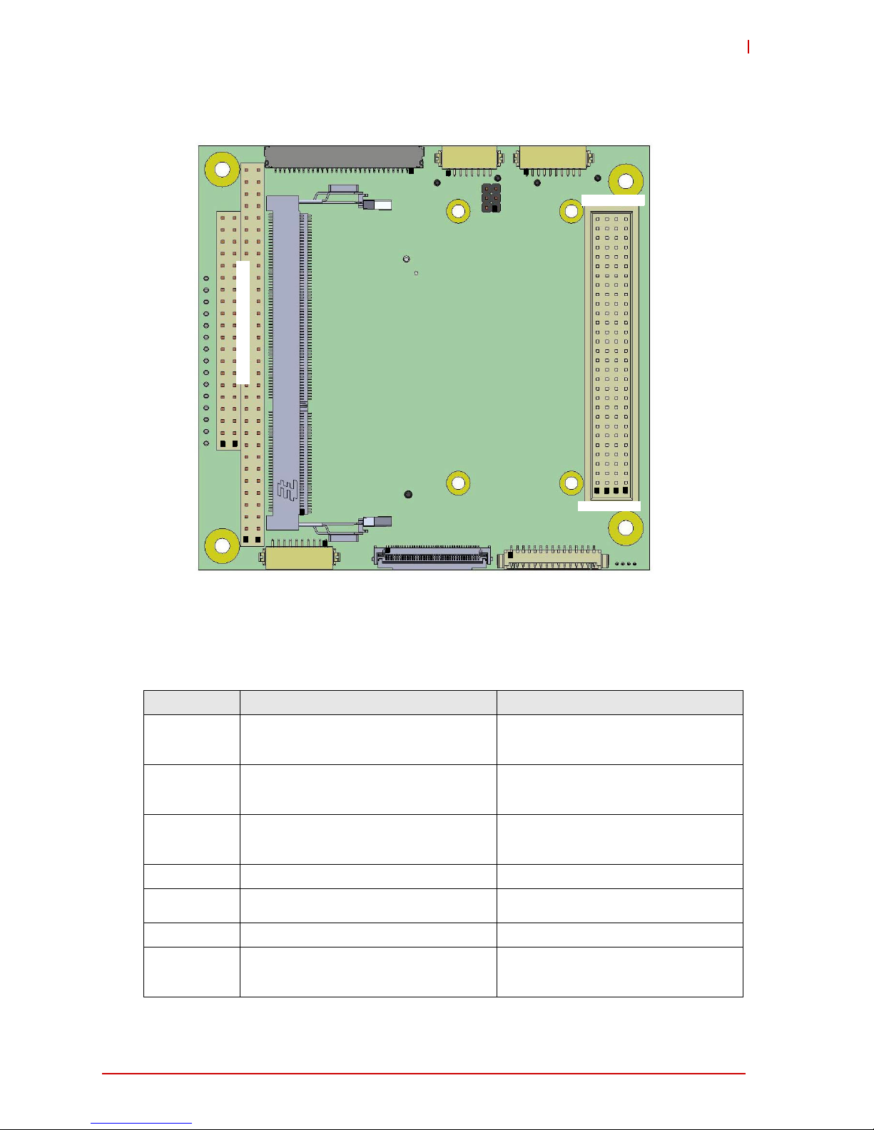
2.1 Header and Connector Locations
Top Side
Figure 2-1: Header and Connector Locations (Top Side)
Table 2-1: Header, Connector, Socket, and Switch Definitions (Top Side)
Connector Description Mating Connector
BAT1 External battery header, 1*2 pins, 1.25mm
pitch for power from external battery (SMP,
W125-0210-310-Z)
Molex, 51021-0200 housing for
50058-8000 terminals
CN1/CN2 Standard PC/104 connector, female Standard PC/104 connector, male
CN7 Standard SATA connector for the 3Gb/s,
SATA1 interface
Standard female SATA
CN8 Standard SATA connector for the 3Gb/s,
SATA2 interface (Shared with mSATA)
Standard female SATA
CN10 Gigabit-Ethernet header, 2*5 pins, 2.0mm
pitch for GbE1 interface
(Molex, 87832-1014)
Molex, 51110-1051 crimp housing for
50394 crimp terminals
CN11 Gigabit-Ethernet header, 2*5 pins, 2.0mm
pitch for GbE2 interface
(Molex, 87832-1014)
Molex, 51110-1051 crimp housing for
50394 crimp terminals
SATA1
(CN7) SATA2
GbE1 GbE2
System
VGA
3x USB 2.0
COM3
mPCIe / mSATA (CN4)
Micro-SD
Slot
SW3 SW4
SW2
COM2
FAN
(CN27) (CN18)
(CN19) (CN16) (CN14)
Panel
(CN20)
Power (CN24)
(CN11)
(CN10)
(CN8)
[full COM interfaces]
(CN28)
PC/104 (CN1/CN2)
CN1
CN2
B1
A1
LEDs 1-13
11
1
1
1
BAT1
1
1
C0 D0
1
1
1
1
1
1
8Getting Started
CN24 ATX Power Input connector, 1*15 pins,
1.5mm pitch
(JST, B15B-EH)
JST, EHR-15 with crimp contacts,
SHE-001T-P0.6
CN20 System panel header, 2*5 pins, 2.0mm pitch
(Molex, 87832-1014)
Molex, 51110-1051 crimp housing for
50394 crimp terminals
CN4 mini-PCIe socket, 1*52 pins, 0.08mm pitch
(shared with mSATA)
8mm, 52-pin mini PCIe edge
connector
CN14 VGA header, 2*5 pins, 2mm pitch
(Molex, 87832-1014)
Molex, 51110-1051 crimp housing for
50394 crimp terminals
CN16 USB 2.0 header, 2*10 pins, 2.0mm pitch
(Molex, 87832-2014)
Molex, 51110-2051 crimp housing for
50394 crimp terminals
CN18 COM 2 header, 2*5 pins, 2.0mm pitch
(Molex, 87832-1014)
Molex, 51110-1051 crimp housing for
50394 crimp terminals
CN19 COM 3 header, 2*5 pins, 2.0mm pitch
(Molex, 87832-1014)
Molex, 51110-1051 crimp housing for
50394 crimp terminals
CN27 FAN connector, 1*4 pins, 1.25mm pitch
(Hirose, DF13-4P-1.25DSA)
Hirose, DF13-4S-1.25C with crimp
contact DF13-2630SCFA (04)
CN28 Micro-SD card, push-pull (no ejection),
hinge-type, standard, right-angle, 1.83mm,
8-pin slot
Micro-SD card
SW2 4-pin, 8.1mm, 25mA 24VDC dip switch for
COM 0/1 termination
N/A
SW3 4-pin, 8.1mm, 25mA 24VDC dip switch for
COM 2/3 termination
N/A
SW4 4-pin, 8.1mm, 25mA 24VDC dip switch for
BIOS Settings
N/A
Getting Started 9
CMx-BTx
Bottom Side
Figure 2-2: Header and Connector Locations (bottom side)
Table 2-2: Header and Connector Definitions (bottom side)
Connector Description Mating Connector
CN13 LVDS connector, Hirose DF19, 1*30 pins,
1.0mm pitch
(Hirose, DF19G-30P-1H)
Hirose, DF19-30S-1C with crimp contact
DF19A-3032 SCF A
CN12 LVDS Backlight connector, Hirose DF13,
1*8 pins, 1.25mm pitch
(Hirose, DF13A-8P-1.25H)
Hirose, DF13-8S-1.25C with crimp
contact DF13-2630 SCF
CN21 User GPIO connector, Hirose DF13, 1*10
pins, 1.25mm pitch
(Hirose, DF13A-10P-1.25H)
Hirose, DF13-10S-1.25C with crimp
contact DF13-2630 SCF
CN22/CN23 Standard PCI-104 connector, male Standard PC/104 connector, female
CN9 Standard DDR3L SODIMM socket DDR3L memory module, non-buffered,
non-ECC
CN1/CN2 Standard PC/104 connector, male Standard PC/104 connector, female
CN26 DB40 debug connector, FFC, 1*40 pins,
0.5mm pitch
(Molex, 502790-4091)
FPC/FFC, 0.3mm thick (+/- 0.05mm)
with 0.5mm pitch
LVDS (CN13)
LVDS
HD Audio
DB40
COM0/1
(CN17)
[4-wire COM interfaces]
(CN26)
(CN15)
SODIMM socket (CN9)
PCI-104 (CN22/CN23)
GPIO
Backlight
(CN12) (CN21)
JP1
1
11
1
1
1
1
11
00
A1 C1D1
B1
CN22
PC/104 (CN1/CN2)
CN2
CN1
CN23
1

10 Getting Started
CN17 COM0/1 connector, Hirose DF13, 1*9 pins,
1.25mm pitch
(Hirose, DF13A9P-1.25H)
Hirose, DF13-10S-1.25C with crimp
contact DF13-2630 SCF
JP1 LCD and Backlight voltage selection
jumper block, 2*3 pins, 2.0mm pitch
2.0mm mini jumper
Getting Started 11
CMx-BTx
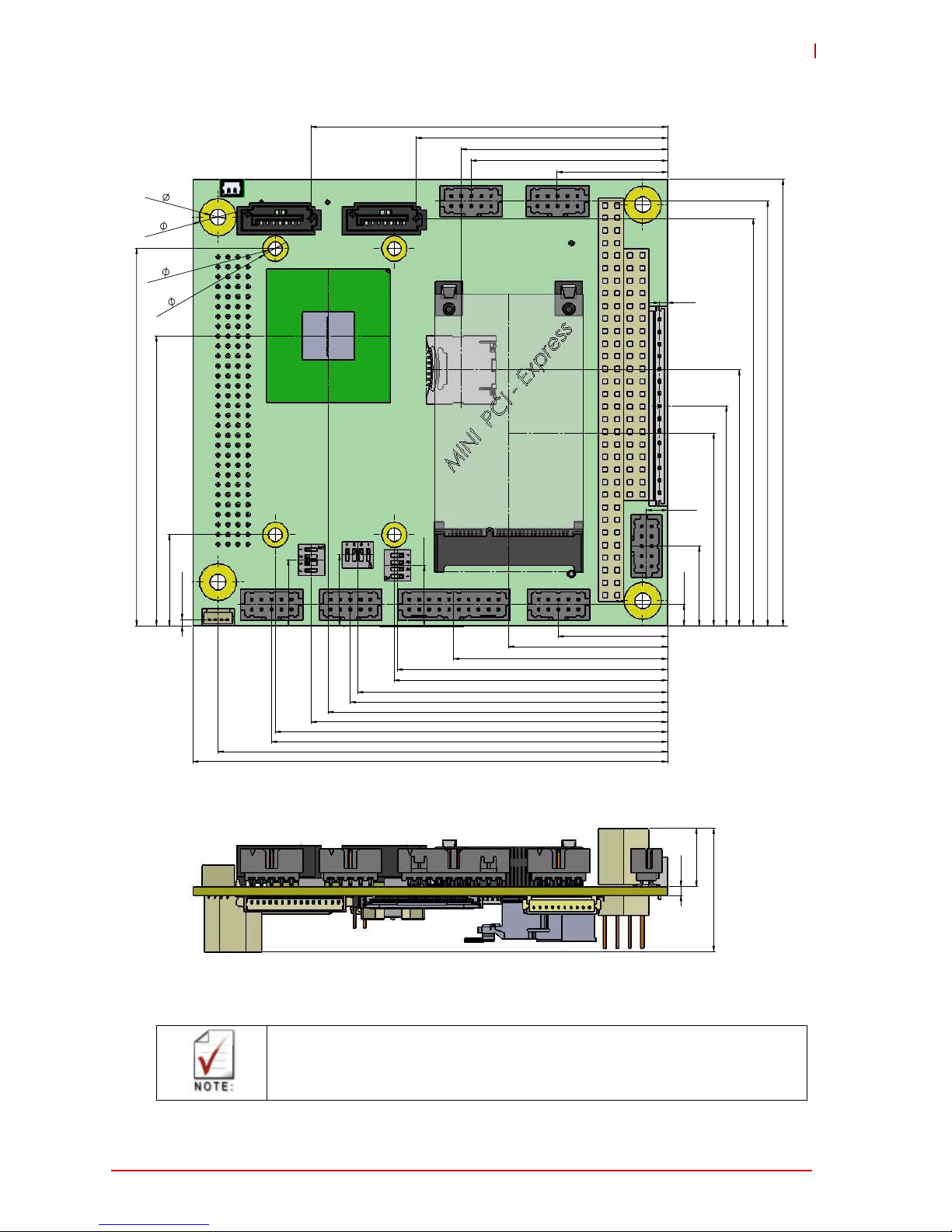
2.2 Mechanical Dimensions
Figure 2-3: Mechanical Dimensions
Mechanical dimensions in Figure 2-3 shown in millimeters.
4,34
22,10
43,20
16,13
4,32
1,67
44,42
39,70
32,10
38,93
54,61
62,61
72,01
64,08
80,01
90,80
12,19
14,35
13,33
1,27
85,80
22,30
68,58
58,55
51,74
41,70
0
0
50,80
72,02
79,25
4x2,7
90,2
7,5
3,2
96
5,1
4x
76,20
4x
55,24
18,42
4x
82,24
24,9
2
11,50
This manual suits for next models
3
Table of contents
Other Fortec Star Motherboard manuals

Fortec Star
Fortec Star conga-PA3 Pico-ITX SBC User manual

Fortec Star
Fortec Star iBase MBB-1000 User manual

Fortec Star
Fortec Star GIGAIPC QBiP-8565A User manual

Fortec Star
Fortec Star Advantech AIMB-586 User manual

Fortec Star
Fortec Star iBASE MB995 User manual

Fortec Star
Fortec Star iBASE IBR210 User manual

Fortec Star
Fortec Star ADVANTECH AIMB-229 User manual

Fortec Star
Fortec Star congatec conga-IC175 User manual


