Fortec Star congatec conga-IC175 User manual
OUR GLOBAL
COMPETENCE
CENTRES
The information contained in this document has been carefully researched and is, to the best of our knowledge, accurate. However, we assume no liability for any
product failures or damages, immediate or consequential, resulting from the use of the information provided herein. Our products are not intended for use in systems
in which failures of product could result in personal injury. All trademarks mentioned herein are property of their respective owners. All specifications are subject to
change without notice.
Manual
congatec
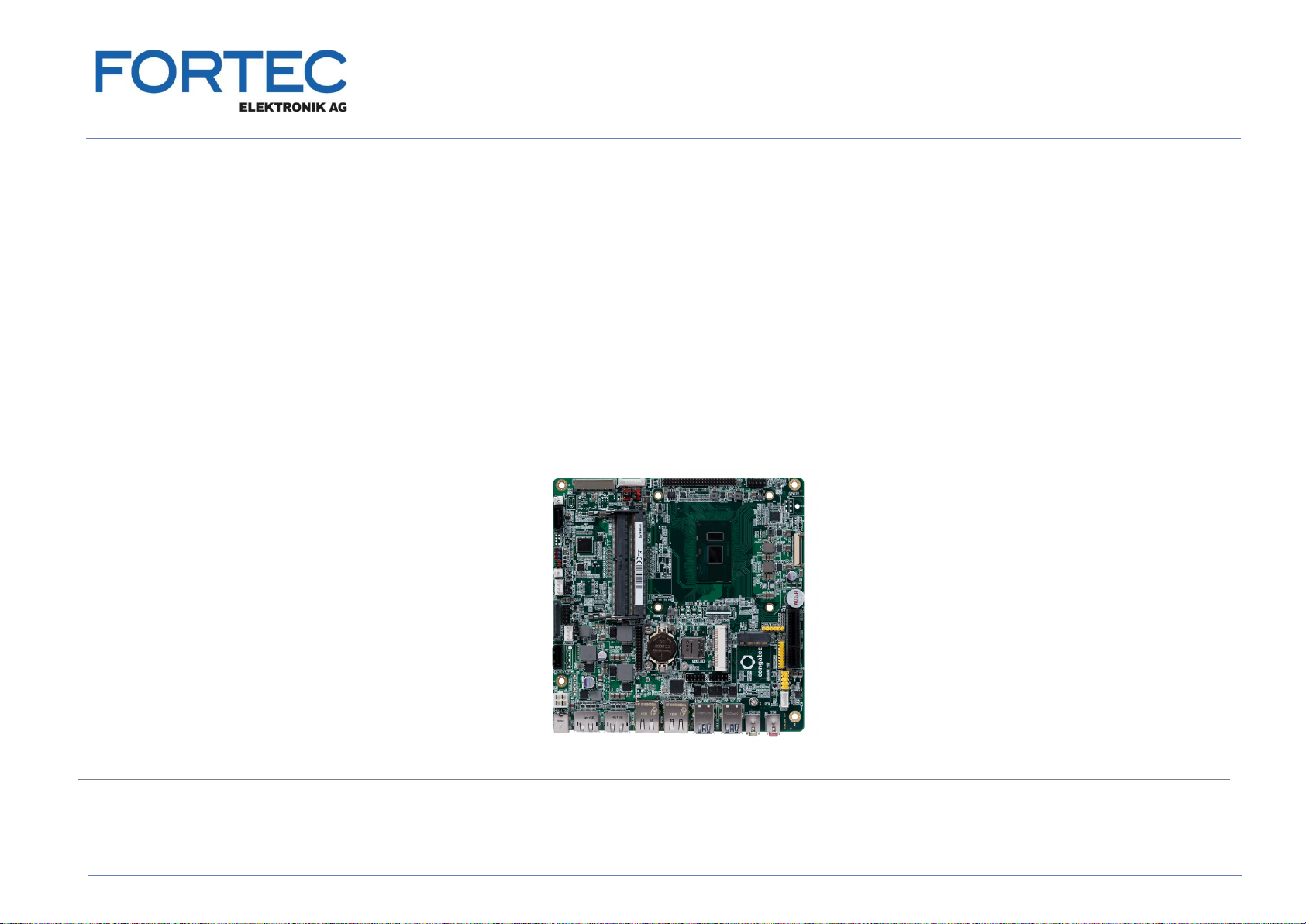
conga-IC175
Mini-ITX Embedded Motherboard with 7. Gen. Intel® Core and Celeron U Processors

conga-IC175 Thin Mini-ITX SBC
Detailed Description Of The congatec Thin Mini-ITX Based On 7th Generation Intel U-Series SoC
User's Guide
Revision 1.1

Copyright © 2017 congatec AG ICKLm11 2/56
Revision History
Revision Date (yyyy-mm-dd) Author Changes
0.1 2017-01-18 AEM •Preliminary release
0.2 2017-12-05 AEM •Updated section 5.8.1 “Standard SATA Connectors”
•Updated table 43 “Feature Connector X38 Pinout Description”
•Added content to section 8 “BIOS Setup Description”
1.0 2018-08-01 AEM •Updated tables 10 “Power Consumption Values” and 11 “CMOS Battery Power Consumption” in section 2.5
•Deleted references to MIPI interface because the conga-IC175 does not support it
•Added note about Wake on LAN from S5 mode in section 5.7 “Ethernet”
•Re-structured the sections
•Official release
1.1 2020-06-15 AEM •Updated section 1.2.2 “Optional Accessories”
•Updated the statement about electrostatic sensitive devices in the preface section
•Corrected power consumption values for PN:052901
•Updated section 4 “Cooling Solution”
•Added section 8.4 “Supported Flash Devices”
•Deleted section 9 “Industry Specifications”

Copyright © 2017 congatec AG ICKLm11 3/56
Preface
This user's guide provides information about the components, features and connectors available on the conga-IC175 Thin Mini-ITX single
board.
Disclaimer
The information contained within this user’s guide, including but not limited to any product specification, is subject to change without notice.
congatec AG provides no warranty with regard to this user’s guide or any other information contained herein and hereby expressly disclaims
any implied warranties of merchantability or fitness for any particular purpose with regard to any of the foregoing. congatec AG assumes
no liability for any damages incurred directly or indirectly from any technical or typographical errors or omissions contained herein or for
discrepancies between the product and the user’s guide. In no event shall congatec AG be liable for any incidental, consequential, special, or
exemplary damages, whether based on tort, contract or otherwise, arising out of or in connection with this user’s guide or any other information
contained herein or the use thereof.
Intended Audience
This user's guide is intended for technically qualified personnel. It is not intended for general audiences.
Lead-Free Designs (RoHS)
All congatec AG products are created from lead-free components and are completely RoHS compliant.
Electrostatic Sensitive Device
All congatec AG products are electrostatic sensitive devices. They are enclosed in static shielding bags, and shipped enclosed in secondary
packaging (protective packaging). The secondary packaging does not provide electrostatic protection.
Do not remove the device from the static shielding bag or handle it, except at an electrostatic-free workstation. Also, do not ship or store
electronic devices near strong electrostatic, electromagnetic, magnetic, or radioactive fields unless the device is contained within its original
packaging. Be aware that failure to comply with these guidelines will void the congatec AG Limited Warranty.
This manual suits for next models
4
Table of contents
Other Fortec Star Motherboard manuals

Fortec Star
Fortec Star GIGAIPC QBiP-8565A User manual

Fortec Star
Fortec Star Advantech AIMB-586 User manual

Fortec Star
Fortec Star iBASE IBR210 User manual

Fortec Star
Fortec Star iBASE MB995 User manual

Fortec Star
Fortec Star ADVANTECH AIMB-229 User manual

Fortec Star
Fortec Star CM1-BT1 User manual

Fortec Star
Fortec Star conga-PA3 Pico-ITX SBC User manual

Fortec Star
Fortec Star iBase MBB-1000 User manual


