Fortec Star ADVANTECH AIMB-229 User manual

The information contained in this document has been carefully researched and is, to the best of our
knowledge, accurate. However, we assume no liability for any product failures or damages, immediate or
consequential, resulting from the use of the information provided herein. Our products are not intended for
use in systems in which failures of product could result in personal injury. All trademarks mentioned herein
are property of their respective owners. All specifications are subject to change without notice.
Manual
ADVANTECH
AIMB-229
Mini-ITX Motherboard with AMD® Ryzen V2000 Embedded Processor

User Manual
AIMB-229
AMD V2000-series Quad Core
Mini-ITX with 2 x HDMI,
2 x DP (Type-C), 8 x USB,
6 x COM, and 12V DC-in

AIMB-229 User Manual ii
Copyright
The documentation and the software included with this product are copyrighted 2022
by Advantech Co., Ltd. All rights are reserved. Advantech Co., Ltd. reserves the right
to make improvements in the products described in this manual at any time without
notice. No part of this manual may be reproduced, copied, translated, or transmitted
in any form or by any means without the prior written permission of Advantech Co.,
Ltd. The information provided in this manual is intended to be accurate and reliable.
However, Advantech Co., Ltd. assumes no responsibility for its use, nor for any
infringements of the rights of third parties that may result from its use.
Acknowledgments
AMI is a trademark of American Megatrends Inc.
IBM and PC are trademarks of International Business Machines Corporation.
AMD V-series is trademark of AMD Corporation.
Nuvoton is a trademark of Nuvoton Technology.
All other product names or trademarks are properties of their respective owners.
Product Warranty (2 years)
Advantech warrants the original purchaser that each of its products will be free from
defects in materials and workmanship for two years from the date of purchase.
This warranty does not apply to any products that have been repaired or altered by
persons other than repair personnel authorized by Advantech, or products that have
been subject to misuse, abuse, accident, or improper installation. Advantech
assumes no liability under the terms of this warranty as a consequence of such
events.
Because of Advantech’s high quality-control standards and rigorous testing, most
customers never need to use our repair service. If an Advantech product is defective,
it will be repaired or replaced free of charge during the warranty period. For out-of-
warranty repairs, customers will be billed according to the cost of replacement mate-
rials, service time, and freight. Please consult your dealer for more details.
If you believe your product to be defective, follow the steps outlined below.
1. Collect all the information about the problem encountered. (For example, CPU
speed, Advantech products used, other hardware and software used, etc.) Note
anything abnormal and list any onscreen messages displayed when the prob-
lem occurs.
2. Call your dealer and describe the problem. Please have your manual, product,
and any helpful information readily available.
3. If your product is diagnosed as defective, obtain a return merchandise authori-
zation (RMA) number from your dealer. This allows us to process your return
more quickly.
4. Carefully pack the defective product, a completed Repair and Replacement
Order Card, and a proof of purchase date (such as a photocopy of your sales
receipt) into a shippable container. Products returned without a proof of pur-
chase date are not eligible for warranty service.
5. Write the RMA number clearly on the outside of the package and ship the pack-
age prepaid to your dealer.
Part No. 2006022900 Edition 1
Printed in China July 2022

iii AIMB-229 User Manual
A Message to the Customer
Advantech Customer Services
Every Advantech product is built to the most exacting specifications to ensure reliable
performance in the harsh and demanding conditions typical of industrial environ-
ments. Whether your new Advantech equipment is destined for the laboratory or fac-
tory floor, you can be assured that your product will provide the reliability and ease of
operation for which the name Advantech has come to be known. Your satisfaction is
our primary concern. Here is a guide to Advantech’s customer services. To ensure
you get the full benefit of our services, please follow the instructions carefully.
Technical Support
We want you to get the maximum performance from your products. So should you
run into technical difficulties, we are here to help. For the most frequently asked
questions, you can find answers in your product documentation. These answers are
normally a lot more detailed than the ones we can provide over the phone. Therefore,
please consult this manual first. If you still cannot find the answer, gather all the infor-
mation or questions that apply to your problem, and with the product close at hand,
call your dealer. Our dealers are well trained and ready to give the support you need
to get the most from your Advantech products. In fact, most problems reported are
minor and can be easily solved over the phone.
In addition, free technical support is available from Advantech engineers every busi-
ness day. We are always ready to give advice regarding application requirements or
specific information regarding the installation and operation of any of our products.
Declaration of Conformity
FCC Class B
This equipment has been tested and found to comply with the limits for a Class B dig-
ital device, pursuant to part 15 of the FCC Rules. These limits are designed to pro-
vide reasonable protection against harmful interference in a residential installation.
This equipment generates, uses, and can radiate radio frequency energy and, if not
installed and used in accordance with the instruction manual, may cause harmful
interference to radio communications. However, there is no guarantee that interfer-
ence will not occur in a particular installation. If this equipment does cause harmful
interference to radio or television reception, which can be determined by turning the
equipment off and on, the user is encouraged to try to correct the interference by one
or more of the following measures:
Reorient or relocate the receiving antenna.
Increase the separation between the equipment and receiver.
Connect the equipment into an outlet on a circuit different from that to which the
receiver is connected.
Consult the dealer or an experienced radio/TV technician for assistance.
Caution! New batteries are at risk of exploding if incorrectly installed. Do not
attempt to recharge, force open, or heat the battery. Replace the battery
only with the same or equivalent type as recommended by the manufac-
turer. Discard used batteries according to the manufacturer's instruc-
tions.

AIMB-229 User Manual iv
Memory Compatibility
Normal RAM Test Data
ECC RAM Test Data
Ordering Information
Category Speed Capacity Vendor ADVANTECH P/N ECC
DDR4 2666 4GB Advantech SQR-SD4N4G2K6SNEFB N
DDR4 2400 4GB Advantech SQR-SD4N4G2K4SNEFB N
DDR4 2666 8GB Advantech SQR-SD4N8G2K6SNBCB N
DDR4 2133 8GB Advantech AQD-SD4U8GN21-SG N
DDR4 3200 8GB Advantech AQD-SD4U8GN32-SE N
DDR4 3200 16GB Advantech SQR-SD4N16G3K2SNCB N
DDR4 2666 16GB Advantech AQD-SD4U16N26-SE N
DDR4 3200 32GB Advantech AQD-SD4U32GN32-SB N
DDR4 2666 32GB Advantech SQR-SD4N32G2K6SNME N
Category Speed Capacity Chip Vendor ADVANTECH P/N ECC
DDR4 2133 16GB Advantech AQD-SD4U16E21-SE ECC
DDR4 3200 8GB Advantech SQR-SD4N8G3K2SEBCB ECC
DDR4 3200 32GB Advantech AQD-SD4U32GE32-SB ECC
DDR4 2400 8GB Advantech AQD-SD4U8GE24-HE ECC
DDR4 2666 4GB Advantech SQR-SD4N4G2K6SEEFB ECC
DDR4 2666 32GB Advantech SQR-SD4N32G2K6SEME ECC
P/N Chipset HDMI eDP DP 1.2 GbE
LAN COM SATAIII USB3.2
Gen2
USB3.2
Gen1 USB2.0 M.2 PCIex8 TPM AMP
AIMB-
229VGG2-
00A1E
V2748
2 x
(HDMI
2.0)
(1) 2 2 6 2 4 2 2 2 1 1 1
AIMB-
229VGG2-
00A2
V2718
2 x
(HDMI
1.4)
(1) 2 2 6 2 4 2 2 2 1 1 (1)
AIMB-
229VGG2-
00A3
V2516
2 x
(HDMI
1.4)
(1) (2) 2 6 2 2 2 2 2 1 1 (1)

v AIMB-229 User Manual
Initial Inspection
Before installing the motherboard, ensure that the following items are included with
the product:
1 x AIMB-229 AMD V2000-series Quad Core Mini-ITX motherboard
1 x SATA HDD cable
1 x SATA power cable
1 x Serial port cable (1-to-1)
1 x Serial port cable (1-to-2)
1 x M.2 POST
2 x M.2 Screws
1 x I/O port bracket
1 x AIMB-229 startup manual
1 x Warranty card
If any of the above items are missing or damaged, contact your distributor or sales
representative immediately. We have carefully inspected the AIMB-229 mechanically
and electrically before shipment. The product should be free of marks and scratches
and in perfect working order upon receipt. While unpacking AIMB-229, check the
product for signs of shipping damage (for example, damaged box, scratches, or
dents). If there is damage or the product fails to meet the specifications, notify our
service department or your local sales representative immediately. Additionally,
please notify the carrier. Retain the shipping carton and packing material for inspec-
tion by the carrier. After inspection, we will make arrangements to repair or replace
the unit.

AIMB-229 User Manual vi

vii AIMB-229 User Manual
Contents
Chapter 1 General Information ............................1
1.1 Introduction ............................................................................................... 2
1.2 Features .................................................................................................... 2
1.3 Specifications ............................................................................................ 2
1.3.1 Processor...................................................................................... 2
1.3.2 Expansion ..................................................................................... 2
1.3.3 Memory ......................................................................................... 2
1.3.4 Graphics Interface......................................................................... 2
1.3.5 Ethernet Interface ......................................................................... 2
1.3.6 SATA Interface.............................................................................. 3
1.3.7 Rear I/O ........................................................................................ 3
1.3.8 Internal Connector ........................................................................ 3
1.3.9 Watchdog Timer............................................................................ 3
1.3.10 Power Requirement ...................................................................... 3
1.3.11 Environment.................................................................................. 3
1.3.12 Physical Characteristics................................................................ 3
1.4 Jumpers and Connectors .......................................................................... 4
Table 1.1: Connector/Header List................................................ 4
Table 1.2: Jumper Setting List..................................................... 5
1.4.1 Voltage Selection for LVDS1/EDP1 Connector (JEDP1).............. 6
1.4.2 CMOS Clear (JCMOS1)................................................................ 6
1.4.3 PWRBTN#/ RESET#/HDD LED/Serial Bus from HW Monitor IC/
Internal Buzzer/External Speaker Header (JFP1)......................... 6
1.4.4 Watchdog Timer Output and OBS Beep (JWDT1+ JOBS1)......... 7
1.4.5 AT/ATX Mode Selection (PSON1) ................................................ 7
1.4.6 Case Open Selection Pin Header (JCASEOP_SW1) ................... 7
1.4.7 COM1_RI# Pin RI#/5V/12V Selection (JSETCOM1_V1).............. 8
1.4.8 COM4_RI# Pin RI#/5V/12V Selection (JSETCOM4_V1).............. 8
1.4.9 CCTalk Power Voltage 5V/12V Select (JCCT_VCON1)............... 9
1.5 Jumper and Connector Locations ............................................................. 9
Figure 1.1 Jumper and Connector Locations (Top Side)............. 9
Figure 1.2 Jumper and Connector Locations (Bottom Side)...... 10
Table 1.3: Connector/Header List.............................................. 10
1.6 Board Diagram ........................................................................................ 12
Figure 1.3 AIMB-229 Board Diagram ........................................ 12
1.7 Safety Precautions .................................................................................. 12
1.8 Jumper Settings ...................................................................................... 13
1.8.1 How to Set Jumpers.................................................................... 13
1.8.2 CMOS Clear (JCMOS1).............................................................. 13
1.8.3 AT/ATX Mode Selection (PSON1) .............................................. 13
1.9 System Memory ...................................................................................... 14
1.10 Memory Installation ................................................................................. 14
Chapter 2 Connecting Peripherals ....................15
2.1 Introduction ............................................................................................. 16
2.2 USB Ports ............................................................................................... 16
2.3 DisplayPort1/2/3/4................................................................................... 17
2.4 Serial Ports (COM1 ~ COM6) ................................................................. 18
2.5 CPU Fan Connector (CPU_FAN1).......................................................... 19
2.6 System Fan Connector (SYSFAN1/2)..................................................... 19
2.7 Power Switch/HDD LED/SMBUS/Speaker Pin Header (JFP1), Power LED,
and Keyboard Lock Pin Header (JFP2) .................................................. 20
2.7.1 ATX Soft Power Switch (JFP1/PWR_SW).................................. 20

AIMB-229 User Manual viii
2.7.2 Reset (JFP1/RESET).................................................................. 20
2.7.3 HDD LED (JFP1/HDDLED) ........................................................ 20
2.7.4 External Speaker (JFP1/SPEAKER) .......................................... 20
2.8 DC Input Jack and 4-Pin ATX Connector (DCIN1) ................................. 21
2.9 SATA Signal and Power Connector (SATA1~SATA2/SATA_PWR1~2). 21
2.10 HD Analog Audio Interface (AUDIO1, AUDIO2, FPAUD1) ..................... 22
2.11 PCI-E x8 Slot (PCIEX8_1) ...................................................................... 23
2.12 Low-Voltage Differential Signaling Interface (EDP1) .............................. 23
2.13 LVDS Backlight Inverter Power Connector (INV1).................................. 24
2.14 NGFF M.2 B-Key and E-Key Connector (M2B1 & M2E1) ...................... 24
2.15 Audio Amplifier Output Connector (AMP1), BOM Optional..................... 25
2.16 General Purpose I/O Pin Header (GPIO1)............................................. 25
2.17 General Purpose I/O Pin Header (BIOS1) .............................................. 26
2.18 SPI Programming Pin Header (BIOS1_CN1) ......................................... 26
2.19 Low-Pin-Count Header (LPC1) ............................................................... 27
2.20 Case-Open Detect Connector (JCASE2)................................................ 27
2.21 CMOS Battery Connector (BAT1)........................................................... 28
2.22 DDR4 SODIMM Socket (DIMMA1, DIMMB1) ......................................... 28
Chapter 3 BIOS Operation ................................. 29
3.1 Introduction ............................................................................................. 30
3.2 BIOS Setup ............................................................................................. 30
3.2.1 Main Menu .................................................................................. 31
3.2.2 Advanced BIOS Features ........................................................... 32
3.3 Chipset Configuration Settings ............................................................... 53
3.3.1 South Bridge Configuration......................................................... 54
3.3.2 GFX Configuration ...................................................................... 56
3.3.3 North Bridge Configuration ......................................................... 57
3.3.4 Platform Misc Configuration........................................................ 57
3.4 Security Settings ..................................................................................... 58
3.5 Boot Setting ............................................................................................ 59
3.6 Save & Exit Configuration ....................................................................... 60
Chapter 4 Software and Services...................... 63
4.1 Introduction ............................................................................................. 64
4.2 Value-Added Software Services ............................................................. 64
4.2.1 Software API............................................................................... 64
4.2.2 Software Utility............................................................................ 66
Chapter 5 Chipset Software Installation Utility 67
5.1 Before Beginning .................................................................................... 68
5.2 Introduction ............................................................................................. 68
5.3 Windows 10 Driver Setup ....................................................................... 68
Chapter 6 LAN Configuration ............................ 69
6.1 Introduction ............................................................................................. 70
6.2 Features.................................................................................................. 70
6.3 Installation............................................................................................... 70
6.4 Windows 10 Driver Setup ....................................................................... 70
Appendix A I/O Pin Assignments ......................... 71

ix AIMB-229 User Manual
A.1 DC-IN Adaptor Connector (DCIN1)......................................................... 72
A.2 HDMI Port Connector (HDMI12) ............................................................. 72
A.3 USB31X2_DP2 ....................................................................................... 73
A.4 USB31X2_DP3 ....................................................................................... 74
A.5 USB34..................................................................................................... 75
A.6 AT/ATX Mode Selection (PSON1) .......................................................... 75
A.7 RJ45(LAN1+LAN2) Connector (LAN12) ................................................. 76
A.8 HD Analog Audio Interface Line-Out (AUDIO1) ...................................... 76
A.9 HD Analog Audio Interface MIC-In (AUDIO2) ......................................... 77
A.10 Audio Amplifier Output Pin Header (AMP1) ............................................ 77
A.11 Front Panel Audio Header (FPAUD1) ..................................................... 78
A.12 CMOS Battery Wafer Box (BAT1)........................................................... 78
A.13 Serial ATA Interface Connector #2 (SATA2)........................................... 78
A.14 HD Audio Interface (SPDIF1).................................................................. 79
A.15 M.2 -Key (NGFF_M1).............................................................................. 79
A.16 EDP Differential Signaling (EDP1) .......................................................... 80
A.17 PCI Express x8 Slot (PCIEX8_1) ............................................................ 81
A.18 USB 2.0 Front-Panel Header (USB56) ................................................... 83
A.19 CPU Fan #1 Connector (CPUFAN1)....................................................... 83
A.20 M.2 E-Key Connector (M2E1) ................................................................. 84
A.21 COM2 Box Header (COM2) .................................................................... 85
A.22 COM1 RI# Selection Pin Header (JSETCOM1_V1) ............................... 85
A.23 Inverter Power Connector (INV1)............................................................ 86
A.24 16-bit General Purpose I/O Pin Header (GPIO1).................................... 86
A.25 COM4 RI Selection Pin Header (JSETCOM4_V1) ................................. 87
A.26 CCTALK Voltage Selection Pin Header (JCCT_VCON1) ....................... 87
A.27 COM3 ~ COM4 Box Header (COM34).................................................... 88
A.28 COM5 ~ COM6 Box Header (COM56)................................................... 88
A.29 COM1 Box Header (COM1) .................................................................... 89
A.30 Low-Pin-Count Interface Connector (LPC1) ........................................... 89
A.31 Serial ATA Power Connector #1 (SATA_PWR1) .................................... 90
A.32 Serial ATA Power Connector #2 (SATA_PWR2) .................................... 90
A.33 DDR4 SODIMM Socket CH-A (DIMMA1) ............................................... 90
A.34 DDR4 SODIMM Socket CH-B (DIMMB1) ............................................... 90
A.35 Power LED & Keyboard Lock Pin Header (JFP2)................................... 91
A.36 Watchdog Timer Output and OBS Beep (JWDT1+JOBS1) .................... 91
A.37 Case Open Connector (JCASE2) ........................................................... 91
A.38 PWRBTN#/RESET#/HDD LED/Serial Bus From HW Monitor IC/Internal
Buzzer/External Speaker Header (JFP1)................................................ 92
A.39 System Fan #2 Connector (SYSFAN2)................................................... 92
A.40 System Fan #1 Connector (SYSFAN1)................................................... 92
A.41 SPI Pin Header (BIOS1_CN1) ................................................................ 93
A.42 SPI BIOS Flash Socket (BIOS1) ............................................................. 93
A.43 VDD Select for LVDS1 Panel (JEDP1) ................................................... 93
A.44 COMS Mode Selection (JCMOS1).......................................................... 94
A.45 VDD Select for LVDS1 Panel (JEDP1) ................................................... 94
A.46 CMOS Clear (JCMOS1).......................................................................... 95
A.47 COM1_RI# Pin Selection (JSETCOM1_V1) ........................................... 95
A.48 COM4_RI# Pin Selection (JSETCOM4_V1) ........................................... 96
A.49 CCTALK Selection Pin Header (JCCT_VCON1) .................................... 96
A.50 AT/ATX Mode Selection (PSON1) .......................................................... 97
A.51 PWRBTN#/RESET#/HDD LED/Serial Bus/Internal Buzzer/External
Speaker Header (JFP1) .......................................................................... 97
A.52 Watchdog Timer Output and OBS Beep (JWDT1+JOBS1) .................... 97

AIMB-229 User Manual x

Chapter 1
1General Information

AIMB-229 User Manual 2
1.1 Introduction
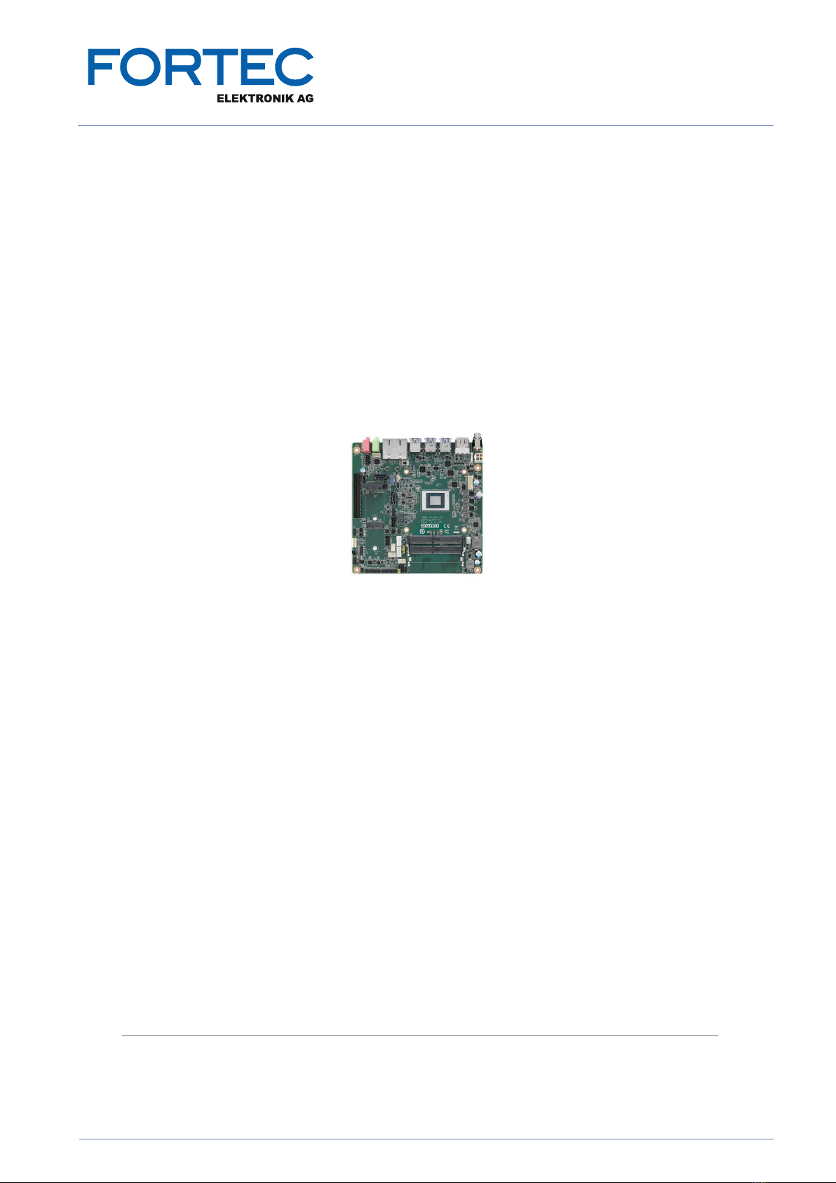
AIMB-229 is a mini-ITX motherboard based on the AMD Ryzen™ embedded V2000
series processor. Designed with diverse I/O and 4 x display outputs, AIMB-229 is
ideal for multi-display applications in digital surveillance, digital signage, electronic
gaming machines, and thin client operations. Advantech’s WISE-PaaS/DeviceOn
supports remote management software and enhances management efficiency.
1.2 Features
Comprehensive I/O: 2 x Display ports, 2 x HDMI, 6 x serial ports, 2 x USB 2.0,
6 x USB 3.2, 2 x SATA III, 2 x GbE LAN, and 16-bit GPIO
Form Factor: Mini-ITX motherboard
Diverse Storage Devices: SATA HDD, M.2 (2242/2280) SSD
Optimized Integrated Graphics: AMD Radeon Graphics, up to 7 x cores, up to
1.6GHz, 4K60 8/10b HVEC/VP9, & 8b H.264 Decode
1.3 Specifications
1.3.1 Processor
CPU: AMD V series, supports 8-core/6-core CPUs
Max. Speed:
–8-core 4.15 GHz (V2748/2718)
–4-core 3.95 GHz (V2516)
L2 Cache: Max. 4 MB
BIOS: AMI 128 Mbit SPI
1.3.2 Expansion
M.2 M Key: 1 x (2242/2280)
M.2 E Key: 1 x (2230)
PCIe x8: 1 x (PCIe Gen3 x8 signal)
1.3.3 Memory
Technology: Dual-channel DDR4 3200 MHz
Max. Capacity: 64 GB (32GB per SODIMM)
Socket: 2 x 260-pin SODIMM
1.3.4 Graphics Interface
Controller: AMD Radeon Graphics
eDP: 1 x (optional), supports dual-channel 48-bit, up to 1920 x colay DP 1.2 port
(optional)
DP 1.2: 2 x, supports DP++, up to 4096 x 2160 @ 60Hzresolution
Multiple Display: 4 x independent displays via DP/HDMI
1.3.5 Ethernet Interface
Interface: 10/100/1000 Mbps
Controller: GbE: Realtek RTL8111H
Connector: 2 x RJ-45

3 AIMB-229 User Manual
Chapter 1 General Information
1.3.6 SATA Interface
Max. Data Transfer Rate: 600 MB/s
Channel: 2 x
1.3.7 Rear I/O
DP: 2 x
Ethernet: 2 x
USB: 4 x (2 x USB 2.0, 6 x USB 3.2)
Audio: 2 x (1 x Line-Out, 1 x Mic-In)
DC Jack: 1 x
1.3.8 Internal Connector
LVDS & Inverter: 1 x (optional)
USB: 2 x (USB 2.0)
Serial: 6 x (5 x RS232,1 x RS232/422/485; COM 2 supports RS232/422/485
auto-flow control; COM 4 supports 5v/12V via jumper selection; 1 x COM sup-
ports CCtalk; 1 x COM supports TTL)
SATA: 2 x
SATA Power Connector: 2 x
GPIO: 16 bit
M.2: 2 x (1 x M-key 2280/2242, 1 x E-key 2230)
1.3.9 Watchdog Timer
Output: System reset
Interval: Programmable 1 ~ 255 sec/min
1.3.10 Power Requirement
Typical:
–Wide voltage range: 12 ~ 24 VDC input via 1 x 2.5φ connector or 1 x internal
2 x 2-pin power (12 V only)
–AT/ATX supported by jumper
–Max. power consumption: 58.4 W (16 GB DDR4 RAM)
1.3.11 Environment
Temperature:
–0 ~ 60 °C (32 ~ 140 °F), operating
–-40 ~ 85 °C (-40 ~ 185 °F), non-operating
1.3.12 Physical Characteristics
Dimensions: 170 x 170 mm (6.69 x 6.69 in)

AIMB-229 User Manual 4
1.4 Jumpers and Connectors
The AIMB-229 motherboard features a number of jumpers and connectors that
enable the integration of external devices, such as hard disk drives and a keyboard,
and configuration according to specific applications.
The function of each board jumper and connector is listed in the tables below. Later
sections in this chapter provide instructions for setting jumpers. Chapter 2 provides
instructions for connecting external devices to the motherboard.
Table 1.1: Connector/Header List
Description Part Reference
1 DC-IN adapter connector DCIN1
2 HDIM Port connector HDMI12
3USB 3.0 Type A and Type C USB31X2_DP2+USB1
4 USB 3.0 Type A and Type C USB31X2_DP3+USB2
5 USB 3.1 Type A USB34
6 AT/ATX Mode selection PSON1
7 RJ45(LAN1+LAN2) connector LAN12
8 HD Analog Audio Interface AUDIO1
9 HD Analog Audio Interface AUDIO2
10 Audio amplifier output pin header AMP1
11 Front panel audio pin header FPAUD1
12 SPDIF interface pin header SPDIF_OUT1
13 Serial ATA interface connector SATA2
14 AMD Hardware Debug Tool HDT1
15 SATADOM power pin header JSATAPWR1
16 M.2 M Key connector NGFF_M1
17 PCI-Express x8 slot PCIEX8_1
18 M.2 E Key connector M2E1
19 COM1 RI# selection pin header JSETCOM1_V1
20 LPC bus interface header LPC1
21 COM1 box header COM1
22 EDP Backlight inverter power connector INV1
23 System fan connector SYSFAN1
24 16-bits General Purpose I/O pin header GPIO1
25 Case open selection pin header JCASEOP_SW1
26 Case open pin header JCASE2
27 BIOS code debug port LED_PORT80
28 COM4 RI# selection pin header JSETCOM4_V1
29 CCTalk power voltage select JCCT_VCON1
30 COM56 box header COM56
31 COM34 box header COM34
32 Power LED JFP2
33 Power switch/HDD LED/SMBus/Speaker JFP1
34 System fan connector SYSFAN2
35 CPU fan connector CPUFAN1
36 SATA power connector SATA_PWR1
37 Watchdog timer output and OBS beep JWDT1+JOBS1
5 AIMB-229 User Manual
Chapter 1 General Information
38 SATA power connector SATA_PWR2
39 ATX Power supply(5VSB) connector ATX_5VSB1
40 DDR3L SO-DIMM socket DIMMA1/DIMMB1
41 BIOS flash pin header BIOS1_CN1
42 COM2 box header COM2
43 SPI BIOS socket BIOS1
44 Dual port USB 2.0 pin header USB56
45 Serial ATA interface connector SATA1
46 eDP panel voltage selection JEDP1
47 eDP panel connector EDP1
48 RTC reset pin header JCMOS1
49 CMOS battery wafer box BAT1
50 ATX 12V power supply connector ATX12V1/ ATX12V2
Table 1.2: Jumper Setting List
Description Part Reference
1 Voltage selection for LVDS1/EDP1 connector JEDP1
2 RTC/CMOS clear JCMOS1
3
PWRBTN#/RESET#/HDD LED/serial bus from
HW monitor IC/internal buzzer/external
speaker header
JFP1
4 Watchdog timer output and OBS beep JWDT1+JOBS1
5 AT/ATX mode selection PSON1
6 Case open selection pin header JCASEOP_SW1
7 COM1_RI# pin selection pin header JSETCOM1_V1
8 COM4_RI# pin selection pin header JSETCOM4_V1
9 CCTalk power voltage select JCCT_VCON1
Table 1.1: Connector/Header List
AIMB-229 User Manual 6
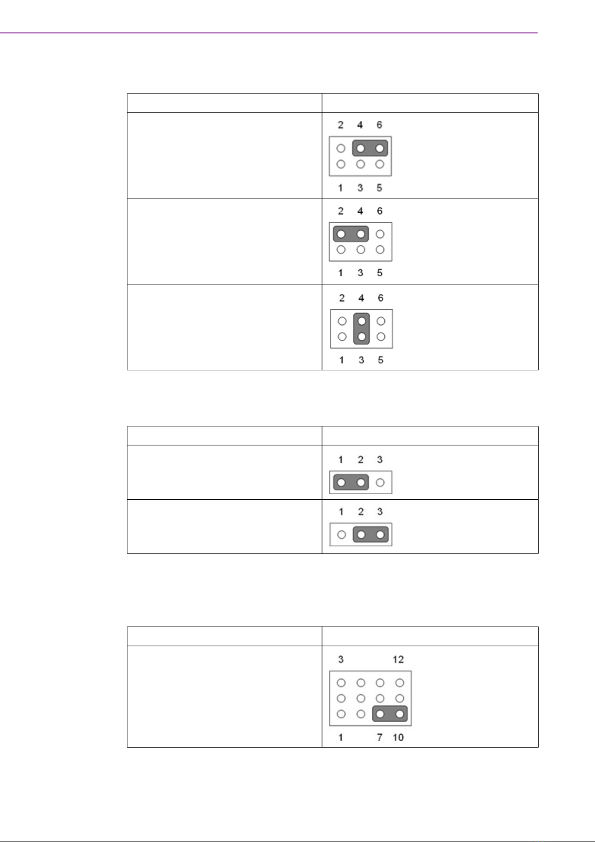
1.4.1 Voltage Selection for LVDS1/EDP1 Connector (JEDP1)
1.4.2 CMOS Clear (JCMOS1)
1.4.3 PWRBTN#/ RESET#/HDD LED/Serial Bus from HW Monitor IC/
Internal Buzzer/External Speaker Header (JFP1)
Function Jumper Setting
Jumper position for +3.3V (default)
Jumper position for +5V
Jumper position for +12V
Function Jumper Setting
Keep CMOS data (default)
Clear CMOS data
Function Jumper Setting
Internal buzzer (default)

7 AIMB-229 User Manual
Chapter 1 General Information
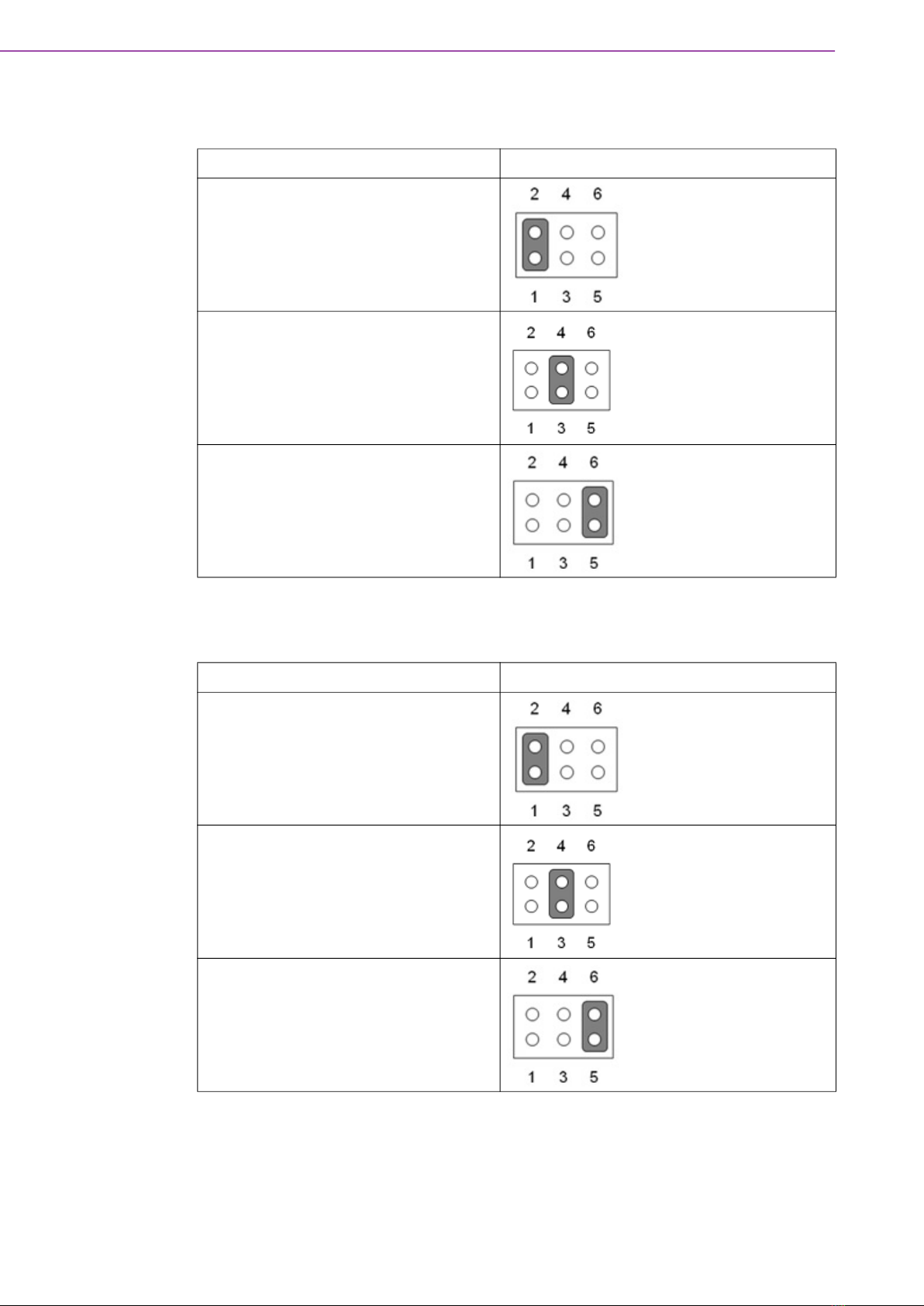
1.4.4 Watchdog Timer Output and OBS Beep (JWDT1+ JOBS1)
1.4.5 AT/ATX Mode Selection (PSON1)
1.4.6 Case Open Selection Pin Header (JCASEOP_SW1)
Function Jumper Setting
Watchdog timer output (2-3) (default)
OBS BEEP(4-5) (default)
Function Jumper Setting
ATX mode (default)
AT mode
Function Jumper Setting
Normal close
Normal open (default)
AIMB-229 User Manual 8
1.4.7 COM1_RI# Pin RI#/5V/12V Selection (JSETCOM1_V1)
1.4.8 COM4_RI# Pin RI#/5V/12V Selection (JSETCOM4_V1)
Function Jumper Setting
Jumper position for RI# (default)
Jumper position for +5V
Jumper position for +12V
Function Jumper Setting
Jumper position for RI# (default)
Jumper position for +5V
Jumper position for +12V
Table of contents
Other Fortec Star Motherboard manuals

Fortec Star
Fortec Star CM1-BT1 User manual

Fortec Star
Fortec Star congatec conga-IC175 User manual

Fortec Star
Fortec Star iBase MBB-1000 User manual

Fortec Star
Fortec Star iBASE IBR210 User manual

Fortec Star
Fortec Star Advantech AIMB-586 User manual

Fortec Star
Fortec Star GIGAIPC QBiP-8565A User manual

Fortec Star
Fortec Star conga-PA3 Pico-ITX SBC User manual

Fortec Star
Fortec Star iBASE MB995 User manual


