Fortin EVO ALL User manual

ADDENDUM - SUGGESTED WIRING CONFIGURATION
ADDENDA - SCHÉMA DE BRANCHEMENT SUGGÉRÉ
ALL REV.: 20160607 GUIDE # 60521
Vehicle functions supported in this diagram (functional if equipped) | Fonctions du véhicule supportées dans ce diagramme
(fonctionnelles si équipé)
VEHICLE
VEHICULES
YEARS
ANNÉES
Immobilizer bypass
Contournement
d’immobilisateur
Lock
Unlock
Arm
Disarm
Parking Lights
Trunk (open)
RAP Disable
Tachometer
Door Status
Trunk Status
Hood Status*
Hand-Brake Status
Foot-Brake Status
Auto-Light Control
OEM Remote monitoring**
HYUNDAI
Sonata
2015-2016
•
•
•
•
•
•
•
•
•
•
•
•
•
•
•
•
HARDWARE VERSION
VERSION MATÉRIELLE FIRMWARE VERSION
VERSION LOGICIELLE This manual may change without notice.
www.fortinbypass.com for latest version.
Ce Guide peut faire l’objet de changement
sans préavis. www.fortinbypass.com pour la
récente version.
MINIMUM 6 76.[29]
HYUNDAI/KIA MINIMUM
NOTES
*Hood Status functional if equipped with a factory hood
switch. fonctionnel si équipé d’un commutateur de capot d’origine.
NOTES
*Hood Status functional if equipped with a factory hood
switch. fonctionnel si équipé d’un commutateur de capot d’origine.
The module will shut down the vehicle as soon
as the drivers door is opened.
Lors de l’ouverture de la porte conducteur le véhicule s’éteindra par
sécurité.
The vehicles OEM remote and SmartKey are
still operable during remote start.
La télécommande d’origine du véhicule et la clé intélligente reste
fonctionnel même si le démarreur est engagé.
The vehicles OEM remote will not be operable
during remote start.
La télécommande d’origine du véhicule ne sera pas fonctionnelle durant
le démarrage à distance.
HYBRID Hybrid compatible remote starter required. Démarreur à distance compatiblle avec véhicule hybride requis.
NO KEY TAKEOVER SANS MODE PRÊT À DÉMARRER
NOTES
**
The vehicles OEM remote will not be
operable during remote start.
La télécommande d’origine du véhicule ne sera pas fonctionnelle
durant le démarrage à distance.
Page 1 / 6
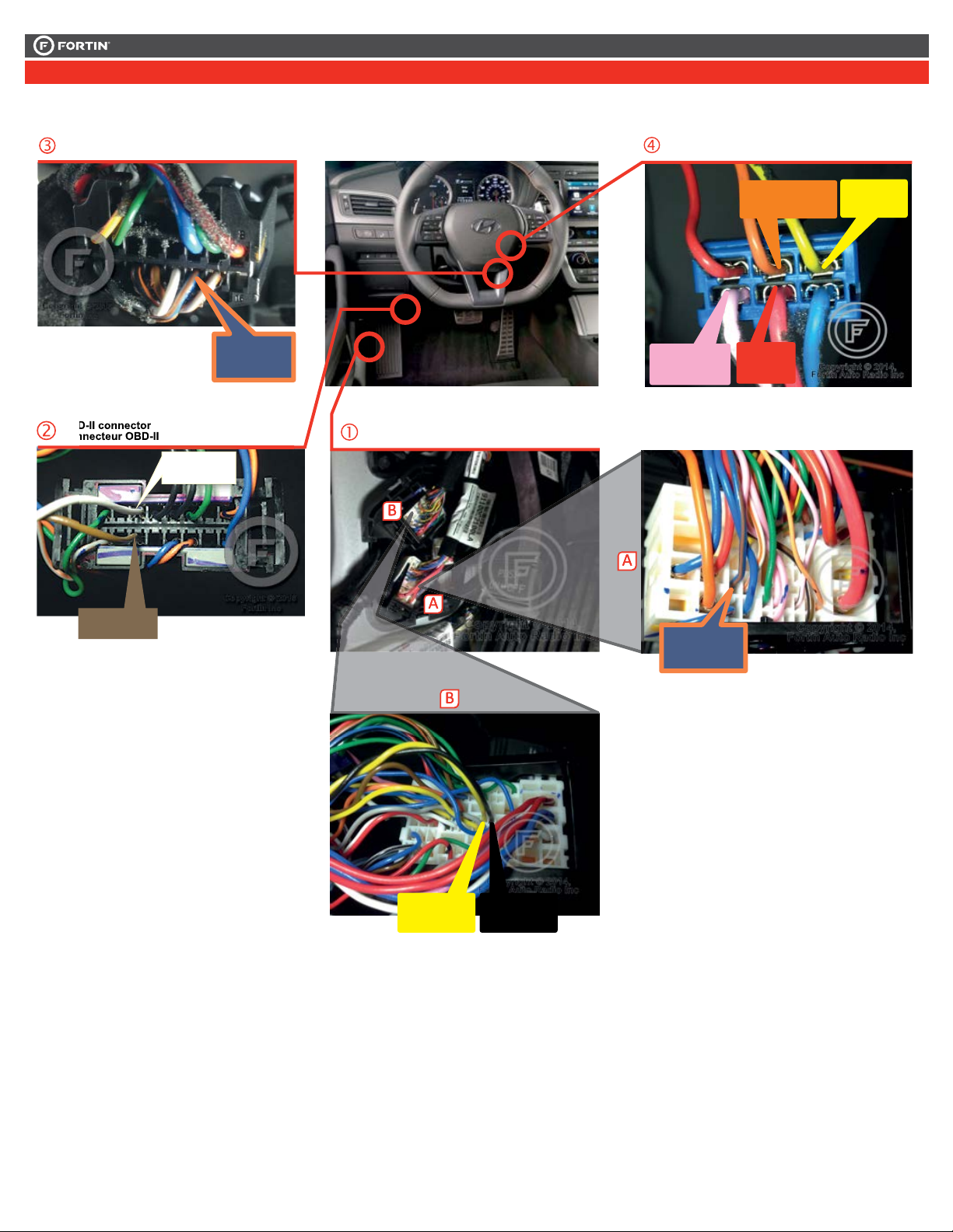
REGULAR INSTALLATION
INSTALLATION RÉGULIÈRE
This guide may change without notice. See www.fortin.ca for latest version.
Ce guide peut faire l’objet de changement sans préavis. Voir www.fortin.ca pour la récente version.
DESCRIPTION | DESCRIPTION
(~) EMS COM
Driver Kick Panel
Panneau latéral côté conducteur
Ignition Barrel
Barillet d'ignition
OBD-II
connector
Connecteur
OBD-II
OBD-II
connector
Connecteur
OBD-II
CAN2 HIGH
CAN2 LOW
CAN1 HIGH CAN1 LOW
At Steering column
À la colonne de direction
(-) PARKING
LIGHTS (+) 12V
(+) START
(+) IGNITION
(+) ACCESSORY
Page 2 / 6

This guide may change without notice. See www.fortin.ca for latest version.
Ce guide peut faire l’objet de changement sans préavis. Voir www.fortin.ca pour la récente version.
In A1
In A2
In A3
Out A4
Out A5
In A6
In A7
In A8
In A9
A10
Out A11
Out A12
In A13
Out A14
Out A15
A16
A17
A18
A19
A20
C5
C4
C3
C2
C1
D6
D5
D4
D3
D2
D1
AC
D
WIRING CONNECTION | GUIDE DE BRANCHEMENTS
WITH | AVEC DATA-LINK:
ALWAYS REQUIRED
TOUJOURS REQUIS
NOT REQUIRED WITH
DATALINK
NON REQUIS EN
DATA-LINK
B
REMOTE
STARTER
DÉMARREUR
À DISTANCE
WITH | AVEC DATA-LINK:
Direct connection
Branchement directe
HOOD IN RS8
(-)
HAND BRAKE IN RS9
(-)
TRUNK RELEASE
(-) OUT RS11
(+/-) IN RS12
TACHOMETER
F
OOT
B
RAKE
(+)
IN RS13
GROUND OUT WHILE RUNNING
(-) OUT RS14
TRUNK
(-)
IN RS15
DOOR
(-) IN RS16
UNLOCK
(-) OUT RS17
LOCK
(-) OUT RS18
A15
A14
A13
A12
A11
A8
A5
A4
A3
A2
Ground | Masse
(-)
RS1
12V BATTERY
RS2 IN
(+)
PARKING LIGHTS
RS4 OUT (+)
ACCESSORY
RS5 OUT (+)
IGNITION
RS6 IN/OUT (+)
STARTER
RS7 OUT (+)
(~)EMS COM(~)EMS COM
(~)EMS COM
(~) EMS COM
(-) Hood Status
(-) Hand Brake
(-) Trunk Release
(-/+) Tachometer
(+) Foot Brake
(-) Ground While Running
(-) Trunk Status
(-) Door Status
(-) Unlock
(-) Lock
(+) Ignion
In
In
In
Back view
47-pin White connector
Vue de dos
Connecteur Blanc de 47 pins
Blue/Orange
Bleu/Orange
19
17
31
18
1
2
3
4
5
6
78
9
10
12 11
20
13
14
1516
21 22
25 24 23
26
27
28
2930
3334353637 32
40 39
41 42
43
44
45
46
47
38
Back View
Blue 6-pin connector
Ignition barrel
Vue de dos
Connecteur Bleu
de 6 pins
Barillet d’Ignition
(~) EMS
COM
Driver kick Panel
Panneau latéral côté
conducteur
4
(+) Ignition (+) Start
Yellow
Jaune
(+) 12V
Red
Rouge
3
(+) Accessory
Orange
Orange
21
5
6
Pink
Rose
CAN1 HIGH CAN1 LOW
Back view
77-pin White connector
Vue de dos
Connecteur Blanc
de 77 pins
Black
Noir
1234567 8
9 10 11 12 13 14 15 16
14
6
CAN2 HIGH CAN2 LOW
White
Blanc
Brown
Brun
OBDII
Front view
OBDII
Vue de face
22
27
52
64
1 2 3 6 8 9 10
20
68 69 70 71 72 73 74 75/ 76 77
56 57 58 59 60 61 62
41 42 43 44 45 46 47 48 49 50
35 36 37
21
26
51
63
40
55
67
39
54
66
38
53
65
4 5 7
14 15 16 17 18 19
28 29 30 31 32 33 34
13
25
12
24
11
23
Yellow
Jaune
US Models: If the (~) EMS COM
wire is not present the vehicle is not equipped
with an immobilizer. For CAN functions use
programming #2. Modèles US: si le fil (~)
EMS COM n'est pas présent, le véhicule n'est
pas équipé d'un transpondeur. Utilisez la
programmation 2 pour les fonctions CAN.
8
161513
1211
10
9
76
5
4
3
21
(MUX) Parking
Lights
Blue/Orange
Bleu/Orange
14
Back View
Black 16-pin connector
At Steering column
Vue de dos
Connecteur Noir
de 16 pins
À la colonne
de direction
Cut
D1
A10 D3
C4C3 C2C1 A18 RS2 A1/RS6
CAN 1 HIGH
CAN 1 LOW
CAN 2 LOW
CAN 2 HIGH
(MUX) Parking Lights
(+) Parking Lights
RS5 RS7
MUST BE FUSED
UN FUSIBLE DOIT
ÊTRE INSTALLÉ
A1
Page 3 / 6
1
EVO-ALLV2_HondaAcura.indd
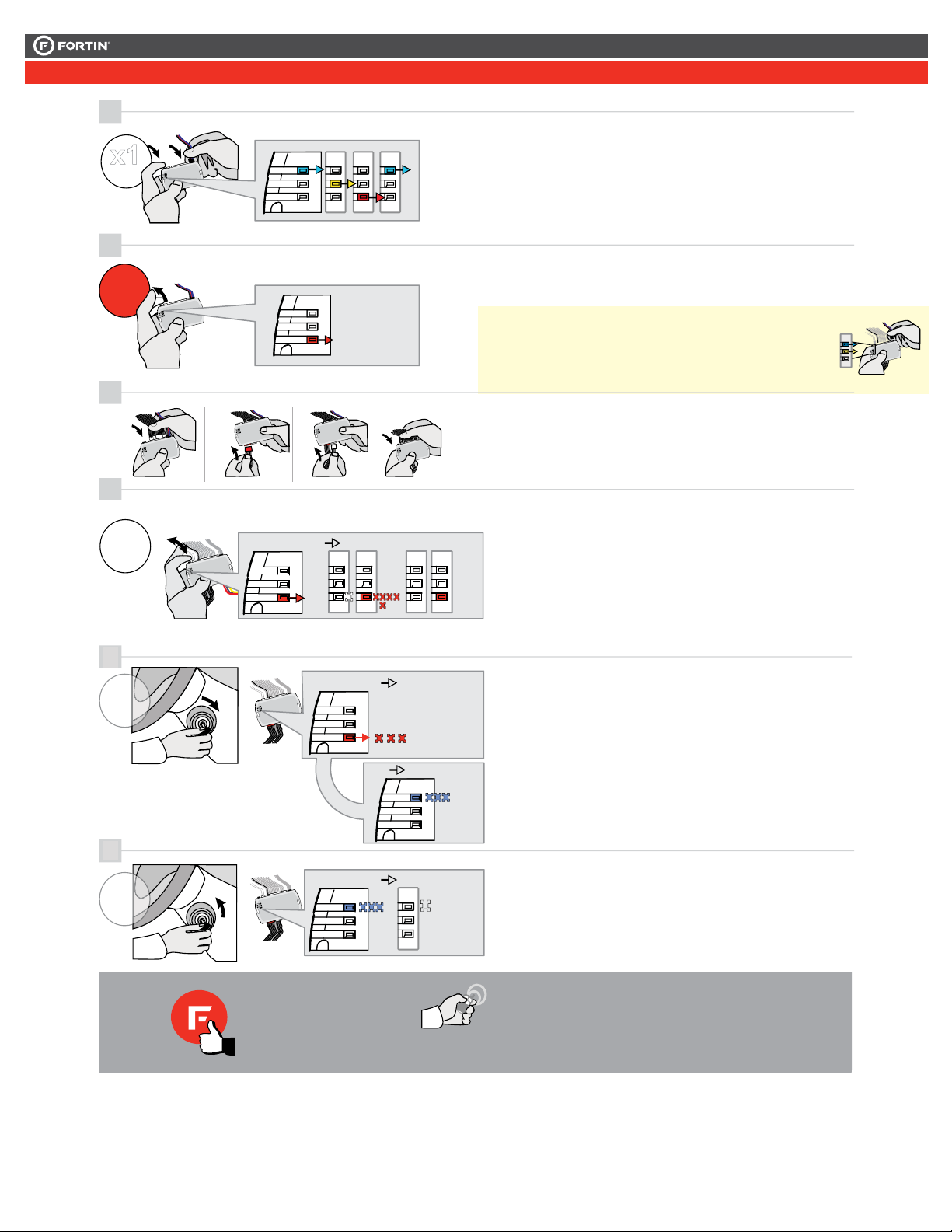
RELEASE
Release the programming
button when the Red LED is
ON.
Insert the required remaining
connectors.
RELEASE
Release the programming
button when the LED is RED.
If the LED is not solid RED
disconnect the 4 Pin
connector (Data-Link) and go
back to step 1.
Insert the required remaining
connectors.
2
3
4
ON RED
ROUGE
Insérez les connecteurs requis
restants.
Relâchez le bouton de
programmation quand la DEL
est ROUGE.
Si le DEL n'est pas ROUGE
solide débranchez le
connecteur 4 pins (Data-Link)
et allez à l'étape 1.
Press and release the
programming button
twice (2x).
x2
PRESS
Appuyez et relâchez 2 fois le
bouton de programmation.
LOCK
ACC ON
PUSH
START
IGN
FLASH 10X
IGNITION ON
6
FLASH RAPIDLY IGNITION OFF
LOCK
ACC ON
PUSH
START
OFF
OFF
The RED LED will flash
rapidly 10x times.
The BLUE LED will flash
rapidly.
Key bypass programmed.
CAN-Bus programmed.
AN-Bus programmed.
La DEL ROUGE clignotera
10x fois rapidement.
La DEL BLEU clignotera
rapidement:
Contournement de clé
programmé.
Réseau CAN programmé.
The BLUE LED will turn off. La DEL BLEU s'éteint.
TURN
ON/RUN
TURN
OFF
5
FLASH 10X
FLASH
The module is now
programmed.
Le module est
programmé.
Use the remote of the remote
starter or security system to test
all of the supported features to
ensure proper programming.
Testez toutes les fonctions
supportées sur le véhicule avec la
télécommande du démarreur à
distance ou du système de sécurité.
Press and hold the
programming button:
Connect the 4-PIN Data-link
harness (Black connector).
The Blue, Red, Yellow and
Blue & Red LEDs will
alternatively illuminate.
Appuyez et maintenir
enfoncé le bouton de
programmation: Branchez le
harnais Data-Link à 4-Broches
(connecteur Noir)
Les DELs Bleue, Rouge,
Jaune et Bleue & Rouge
s'allumeront alternativement.
Tournez la clé à Ignition.
Turn the key to the
Ignition ON/RUN position.
Turn the key to the
OFF position.
Tournez la clé à la
position Arrêt (OFF).
x1
HOLD
LED may differ depending on the module casing.
L’apparence des DELS peuvent différer selon le
boîtier du module.
The RED LED will flash
once each second.
La DEL ROUGE clignote 1
fois chaque seconde.
ON
...
1
2
3
4
ON Red
Rouge
Insérez les connecteurs requis
restants.
Press and release the
programming button once
(1x).
5
x1
PRESS
Appuyez et relâchez 1 fois le
bouton de programmation.
The Red LED will turn OFF
and then back ON.
La DEL Rouge s'éteindra et
se rallumera.
OFF
ON
PRESS X1
OFF
ON
ON
LOCK
ACC ON
PUSH
START
IGN
FLASH 10X
IGNITION ON
7
FLASH RAPIDLY IGNITION OFF
LOCK
ACC ON
PUSH
START
OFF
OFF
The Blue LED will flash
rapidly.
CAN-Bus programmed.
La DEL Bleue clignotera
rapidement:
Réseau CAN programmé.
The Blue LED will turn off. La DEL Bleue s'éteint.
TURN
ON/RUN
TURN
OFF
6
FLASH 10X
Press and release the
programming button once
(1x).
x1
PRESS
Appuyez et relâchez 1 fois le
bouton de programmation.
The Red LED will flash 1
once each second.
La DEL Rouge clignote 1
fois chaque seconde.
FLASH
ON
PRESS X1
...
FLASH
x1
HOLD
Press and hold the
programming button:
Insert the 4-Pin (Data-Link)
connector.
Appuyez et maintenir
enfoncé le bouton de
programmation:
Insérez le connecteur 4 pins
(Data-Link)
The Blue, Red, Yellow and
Blue & Red LEDs will
alternatively illuminate.
Les DELs Bleue, Rouge,
Jaune et Bleue & Rouge
s'allumeront alternativement.
Relâchez le bouton de
programmation quand la DEL
Rouge est allumée.
If the Red LED is not ON solid
disconnect the 4-PIN Data-Link
harness (Black connector) and
go back to step 1.
Si la DEL Rouge n'est pas
allumée, débranchez le harnais
Data-Link à 4-Pins et retournez
au début de l'étape 1.
Turn the key to the Ignition
ON/RUN position.
Tournez la clé à la position
Allumage ON/RUN.
Turn the key to the OFF
position.
Tournez la clé à la position
Arrêt (OFF)
The module is now
programmed.
Le module est
programmé.
Use the remote of the remote starter /
security system to test all the
supported features and ensure all the
features are properly programmed.
Testez toutes les fonctions supportées sur
le véhicule avec la télécommande du
démarreur à distance / système de sécurité
afin de vous assurer que toutes les
fonctions sont bien programmées.
The Red LED will flash 10
times rapidly.
Key bypass programmed.
La DEL Rouge clignotera
10 fois rapidement.
Contournement de clé
programmé.
1
EVO-ALLV2_HondaAcura.indd
RELEASE
Release the programming
button when the Red LED is
ON.
Insert the required remaining
connectors.
RELEASE
Release the programming
button when the LED is RED.
If the LED is not solid RED
disconnect the 4 Pin
connector (Data-Link) and go
back to step 1.
Insert the required remaining
connectors.
2
3
4
ON RED
ROUGE
Insérez les connecteurs requis
restants.
Relâchez le bouton de
programmation quand la DEL
est ROUGE.
Si le DEL n'est pas ROUGE
solide débranchez le
connecteur 4 pins (Data-Link)
et allez à l'étape 1.
Press and release the
programming button
twice (2x).
x2
PRESS
Appuyez et relâchez 2 fois le
bouton de programmation.
LOCK
ACC ON
PUSH
START
IGN
FLASH 10X
IGNITION ON
6
FLASH RAPIDLY IGNITION OFF
LOCK
ACC ON
PUSH
START
OFF
OFF
The RED LED will flash
rapidly 10x times.
The BLUE LED will flash
rapidly.
Key bypass programmed.
CAN-Bus programmed.
AN-Bus programmed.
La DEL ROUGE clignotera
10x fois rapidement.
La DEL BLEU clignotera
rapidement:
Contournement de clé
programmé.
Réseau CAN programmé.
The BLUE LED will turn off. La DEL BLEU s'éteint.
TURN
ON/RUN
TURN
OFF
5
FLASH 10X
FLASH
The module is now
programmed.
Le module est
programmé.
Use the remote of the remote
starter or security system to test
all of the supported features to
ensure proper programming.
Testez toutes les fonctions
supportées sur le véhicule avec la
télécommande du démarreur à
distance ou du système de sécurité.
Press and hold the
programming button:
Connect the 4-PIN Data-link
harness (Black connector).
The Blue, Red, Yellow and
Blue & Red LEDs will
alternatively illuminate.
Appuyez et maintenir
enfoncé le bouton de
programmation: Branchez le
harnais Data-Link à 4-Broches
(connecteur Noir)
Les DELs Bleue, Rouge,
Jaune et Bleue & Rouge
s'allumeront alternativement.
Tournez la clé à Ignition.
Turn the key to the
Ignition ON/RUN position.
Turn the key to the
OFF position.
Tournez la clé à la
position Arrêt (OFF).
x1
HOLD
LED may differ depending on the module casing.
L’apparence des DELS peuvent différer selon le
boîtier du module.
The RED LED will flash
once each second.
La DEL ROUGE clignote 1
fois chaque seconde.
ON
...
1
2
3
4
ON Red
Rouge
Insérez les connecteurs requis
restants.
Press and release the
programming button once
(1x).
5
x1
PRESS
Appuyez et relâchez 1 fois le
bouton de programmation.
The Red LED will turn OFF
and then back ON.
La DEL Rouge s'éteindra et
se rallumera.
OFF
ON
PRESS X1
OFF
ON
ON
LOCK
ACC ON
PUSH
START
IGN
FLASH 10X
IGNITION ON
7
FLASH RAPIDLY IGNITION OFF
LOCK
ACC ON
PUSH
START
OFF
OFF
The Blue LED will flash
rapidly.
CAN-Bus programmed.
La DEL Bleue clignotera
rapidement:
Réseau CAN programmé.
The Blue LED will turn off. La DEL Bleue s'éteint.
TURN
ON/RUN
TURN
OFF
6
FLASH 10X
Press and release the
programming button once
(1x).
x1
PRESS
Appuyez et relâchez 1 fois le
bouton de programmation.
The Red LED will flash 1
once each second.
La DEL Rouge clignote 1
fois chaque seconde.
FLASH
ON
PRESS X1
...
FLASH
x1
HOLD
Press and hold the
programming button:
Insert the 4-Pin (Data-Link)
connector.
Appuyez et maintenir
enfoncé le bouton de
programmation:
Insérez le connecteur 4 pins
(Data-Link)
The Blue, Red, Yellow and
Blue & Red LEDs will
alternatively illuminate.
Les DELs Bleue, Rouge,
Jaune et Bleue & Rouge
s'allumeront alternativement.
Relâchez le bouton de
programmation quand la DEL
Rouge est allumée.
If the Red LED is not ON solid
disconnect the 4-PIN Data-Link
harness (Black connector) and
go back to step 1.
Si la DEL Rouge n'est pas
allumée, débranchez le harnais
Data-Link à 4-Pins et retournez
au début de l'étape 1.
Turn the key to the Ignition
ON/RUN position.
Tournez la clé à la position
Allumage ON/RUN.
Turn the key to the OFF
position.
Tournez la clé à la position
Arrêt (OFF)
The module is now
programmed.
Le module est
programmé.
Use the remote of the remote starter /
security system to test all the
supported features and ensure all the
features are properly programmed.
Testez toutes les fonctions supportées sur
le véhicule avec la télécommande du
démarreur à distance / système de sécurité
afin de vous assurer que toutes les
fonctions sont bien programmées.
The Red LED will flash 10
times rapidly.
Key bypass programmed.
La DEL Rouge clignotera
10 fois rapidement.
Contournement de clé
programmé.
5
6
ON
Press releaseand the
programming button
Appuyez relâchezet
bouton de programmation.
The RED LED will flash La DEL ROUGE clignote
fois chaque seconde.
PRESS
FLASHPRESS
...
fois le
x6 X5X6
(6x).
6
6 times
5
5 times each second.
This guide may change without notice. See www.fortin.ca for latest version.
Ce guide peut faire l’objet de changement sans préavis. Voir www.fortin.ca pour la récente version.
PROGRAMMING PROCEDURE | PROCÉDURE DE PROGRAMMATION
Page 4 / 6
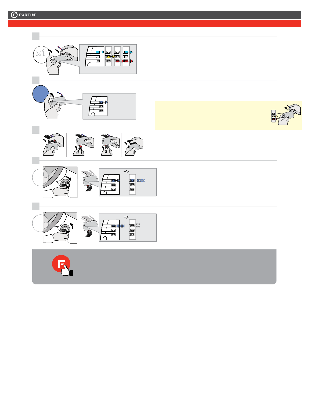
RELEASE
PROGRAMMING PROCEDURE | PROCÉDURE DE PROGRAMMATION
Release the programming
button when the LED is BLUE.
If the LED is not solid BLUE
disconnect the 4-Pin connector
(Data-Link) and go back to step 1.
ON
Insert the required remaining
connectors.
2
3
4
BLUE
BLEU
LOCK
ACC ON
PUSH
START
IGN
FLASH RAPIDLY
ON
IGNITION OFF
5
FLASH RAPIDLY IGNITION OFF
LOCK
ACC ON
PUSH
START
OFF
OFF
The module is now
programmed.
Le module est
programmé.
Insérez les connecteurs requis
restants.
Relâchez le bouton de
programmation quand la DEL
est BLEU.
Si le DEL n'est pas BLEU
débranchez le connecteur 4
pins (Data-Link) et allez au
début de l'étape 1.
The BLUE LED will flash
rapidly.
La DEL BLEU clignotera
rapidement.
The BLUE LED will turn off. La DEL BLEU s'éteint.
TURN
ON/RUN
TURN
OFF
1
ALL_NISSANINFINITI_CAHIER_ALL_Rev3.indd
Press and hold the
programming button:
Connect the 4-PIN Data-link
harness (Black connector).
The Blue, Red, Yellow and
Blue & Red LEDs will
alternatively illuminate.
Appuyez et maintenir
enfoncé
le bouton de
programmation:
Branchez le
harnais Data-Link à 4-Broches
(connecteur Noir)
Les DELs Bleue, Rouge,
Jaune et Bleue & Rouge
s'allumeront alternativement.
T
ournez la clé à Ignition.
T
urn the key to the
Ignition ON/RUN position.
T
urn the key to the
OFF position.
T
ournez la clé à la
position
Arrêt (OFF).
x1
HOLD
LED may differ depending on the module casing.
L’apparence des DELS peuvent différer selon le
boîtier du module.
This guide may change without notice. See www.fortin.ca for latest version.
Ce guide peut faire l’objet de changement sans préavis. Voir www.fortin.ca pour la récente version.
PROGRAM.: 2 VEHICULE WITHOUT EMS COM WIRE | VÉHICULE SANS FIL EMS COM
Page 5 / 6

ALL
Service No : 000 102 04 2536
Date: xx-xx
INTERFACE MODULE
Made in Canada
PATENTS PENDING US: 2007-228827-A1
www.fortinbypass.com
HARDWARE VERSION
FIRMWARE VERSION
Module label | Étiquette sur le module
Notice: Updated Firmware and Installation Guides
Updated fi rmware and installation guides are posted on our web site on a regular
basis. We recommend that you update this module to the latest firmware and
download the latest installation guide(s) prior to the installation of this product.
Notice: Mise à jour microprogramme et Guides d’installations
Des mises à jour du Firmware (microprogramme) et des guides d’installation
sont mis en ligne régulièrement. Vérifiez que vous avez bien la dernière version
logiciel et le dernier guide d’installation avant l’installation de ce produit.
WARNING
The information on this sheet is provided on an (as is) basis with no representation or warranty of accuracy whatsoever.
It is the sole responsibility of the installer to check and verify any circuit before connecting to it. Only a computer safe
logic probe or digital multimeter should be used. FORTIN ELECTRONIC SYSTEMS assumes absolutely no liability or
responsibility whatsoever pertaining to the accuracy or currency of the information supplied. The installation in every case
is the sole responsibility of the installer performing the work and FORTIN ELECTRONIC SYSTEMS assumes no liability
or responsibility whatsoever resulting from any type of installation, whether performed properly, improperly or any other
way. Neither the manufacturer or distributor of this module is responsible of damages of any kind indirectly or directly
caused by this module, except for the replacement of this module in case of manufacturing defects. This module must be
installed by qualified technician. The information supplied is a guide only. This instruction guide may change without
notice. Visit www.fortinbypass.com to get the latest version.
MISE EN GARDE
L’information de ce guide est fournie sur la base de représentation (telle quelle) sans aucune garantie de précision et
d’exactitude. Il est de la seule responsabilité de l’installateur de vérifier tous les fils et circuits avant d’effectuer les connexions.
Seuls une sonde logique ou un multimètre digital doivent être utilisés. FORTIN SYSTÈMES ÉLECTRONIQUES n’assume
aucune responsabilité de l’exactitude de l’information fournie. L’installation (dans chaque cas) est la responsabilité de
l’installateur effectuant le travail. FORTIN SYSTÈMES ÉLECTRONIQUES n’assume aucune responsabilité suite à
l’installation, que celle-ci soit bonne, mauvaise ou de n’importe autre type. Ni le manufacturier, ni le distributeur ne se
considèrent responsables des dommages causés ou ayant pu être causés, indirectement ou directement, par ce module,
excepté le remplacement de ce module en cas de défectuosité de fabrication. Ce module doit être installé par un technicien
qualifié. L’information fournie dans ce guide est une suggestion. Ce guide d’instruction peut faire l’objet de changement
sans préavis. Consultez le www.fortinbypass.com pour voir la plus récente version.
Copyright © 2006-2014, FORTIN AUTO RADIO INC ALL RIGHTS RESERVED PATENT PENDING
TECH SUPPORT
Tél: 514-255-HELP (4357)
1-877-336-7797
ADDENDUM GUIDE WEB UPDATE | MISE À JOUR INTERNET
www.fortinbypass.com
EVO-ALL
Page 6 / 6
Other manuals for EVO ALL
34
This manual suits for next models
1
Other Fortin Control Unit manuals


Popular Control Unit manuals by other brands

Assa Abloy
Assa Abloy Effeff ePED 1386CMC Installation and operating instructions

MDT
MDT SCN-LOG1.02 operating instructions

ICPDAS
ICPDAS ET-2200 Series user manual

GE
GE CR194 installation instructions

oventrop
oventrop Regufloor H Installation and operating instructions for the specialised installer

Aaeon
Aaeon PFM-T096P manual


hilscher
hilscher COM-C Series Design guide

Siemens
Siemens SIMATIC RTLS4330G operating instructions

schmersal
schmersal SRB 301LC/B operating instructions

ASCO Valves
ASCO Valves 8222 Series Installation & maintenance instructions

Hitachi
Hitachi IR.LINK user manual

Bike Sport Developments
Bike Sport Developments Blip Box-Pro manual