Management
Management
Factory
Reset
Normal
Mode
INT 1
INT 2
EXT 1
EXT 2
EXT 2INT 2
DC+5V
PWR CONSOLE MODEM
TO FORTIGATE
EXT 1 MANAGEMENT
INT 1
PWR
INT 1
INT 2
MANAGEMENT
NORMAL
EXT 2
EXT 1 BYPASS MODE
MODE
F
FortiGate
Esc Enter
FACTORY RESET
Power
Change
Mode
Bypass
Mode
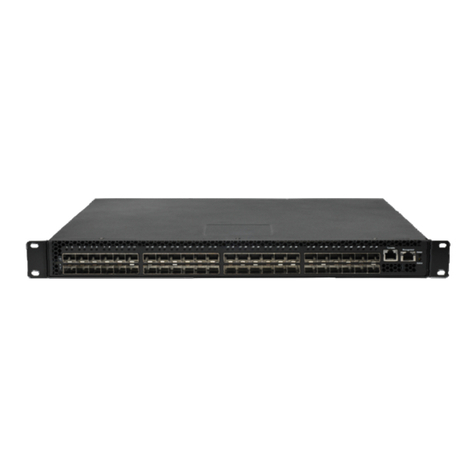
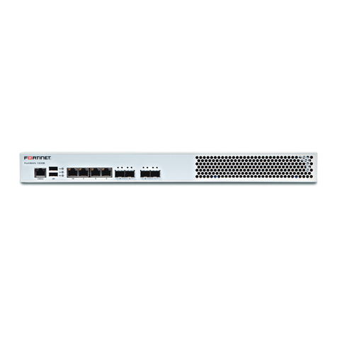
FortiBridge-1000
QuickStart Guide
Copyright 2005 Fortinet Incorporated. All rights reserved.
Trademar ks
Products mentioned in this document are trademarks.
Power Cable Power Supply
RJ-45 to
DB-9 Serial Cable
Power
FortiGate unit
connections
Network
connections
Console
Front
Back
INT 2
EXT 2
Modem INT 1
EXT 1
PWR
INT1
INT2 NORMAL
EXT2
EXT1 BYPASSMODE
MODE FACTORYRESET
FortiGate
EscEnter
Documentation
4 1000Base-SX
SFP Transceivers
EXT 2INT 2
DC+5V
PWR CONSOLE MODEM
TO FORTIGATE
EXT 1 MANAGEMENT
INT 1
Router
INT 1
INT 2
EXT 1
EXT 2
Internal
Gigabit
Fiber
Gigabit
Fiber
Gigabit
Fiber
Gigabit
Fiber
External
(Trans
arent mode)
Internal network
Internet
Switch Switch
Gigabit Fiber connection to FortiGate External interface
Power cable connects to power supply
Gigabit Fiber connection to FortiGate Internal interface
Gigabit Fiber connection to Internal network
Gigabit Fiber connection to External network
Optional Gigabit Fiber connection
for out of band management
Optional RJ-45 serial cable connects to management computer
Check that the package contents are complete.
Checking the package contents
1
LED Indicators
Connectors
LED State Description
PWR Green The FortiBridge unit is powered on.
Off The FortiBridge unit is powered off.
INT1,INT 2,
EXT 1, and
EXT 2
Green The correct optical fiber patch cable is
connected to the gigabit fiber interface.
Flashing Network activity at the gigabit fiber
interface.
Connector Type Speed Protocol Description
INT 1, INT 2,
EXT 1,
EXT 2, and
management
LC SFP 1000Base
-SX Ethernet
Multimode fiber optic
connections to gigabit optical
networks. The FortiBridge-
1000F is shipped with 4
1000Base-SX Small
Formfactor Pluggable (SFP)
transceivers that you must
insert into the INT 1, INT 2,
EXT 1, and EXT 2 sockets on
the back panel. The
management connection is
optional.
CONSOLE RJ-45 9600 bps RS-232
serial Console connection to the
command line interface (CLI).
Connect the FortiBridge unit to the internal and external networks and the
FortiGate unit. Connect the power cable to the FortiBridge unit.
Connecting the FortiBridge
2
• Connect the FortiBridge INT 2 interface to the
FortiGate unit internal interface.
• Connect the FortiBridge EXT 2 interface to the
FortiGate unit external interface.
• Connect the FortiBridge INT 1 interface to the
internal network.
• Connect the FortiBridge EXT 1 interface to the
external network.
• Optionally connect the FortiBridge Management
interface to your network.
• Turn on the FortiGate unit and any network
equipment that was turned off.
• Connect the AC adapter to the power connection at
the back of the FortiBridge unit and to a power
outlet.
The PWR and Bypass Mode LEDs turn on. After a short
time, the FortiBridge unit switches to Normal mode. The
Bypass LED turns off and the Normal LED turns on.
PWR
INT 1
INT 2
MANAGEMENT
NORMAL
EXT 2
EXT 1 BYPASS MODE
MODE
F
FortiGate
Esc Enter
FACTORY RESET
The FortiBridge unit functions as a pass-through device when a
FortiGate unit or FortiGate HA cluster operating in Transparent mode
fails or loses power. The FortiBridge unit bypasses the FortiGate unit to
make sure that the network can continue processing traffic. The
FortiBridge unit is not a firewall or antivirus device. FortiGate services
are not applied when the FortiBridge unit bypasses traffic.
© Copyright 2006 Fortinet Incorporated. All rights reserved.
Trademarks
Products mentioned in this document are trademarks or registered trademarks of their
respective holders.
Regulatory Compliance
FCC Class A Part 15 CSA/CUS
9 November 2006
QuickStart Guide
FortiBridge-1000F
09-30000-0219-20061109
Default settings
Administrator account admin
Password (none)
Management IP 192.168.1.99
Netmask 255.255.255.0
Management Access Telnet and ping access to the INT 1
Management interfaces.
