manuals.online logo
Brands
  1. Home
  2. •
  3. Brands
  4. •
  5. Fortinet
  6. •
  7. Switch
  8. •
  9. Fortinet FortiWeb-1000B User manual

Fortinet FortiWeb-1000B User manual

© Copyright 2008–2017 Fortinet Incorporated. All rights reserved.
Products mentioned in this document are trademarks or registered trademarks
of their respective holders.
Regulatory Compliance
FCC Class A Part 15 CSA/CUS
Bureau of Standards Metrology and Inspection (BSMI) – Taiwan
The presence conditions of the restricted substance (BSMI RoHS table) are
available at the link below:
https://www.fortinet.com/bsmi
December 15, 2017
Connecting
R
1000B
For future
useUSB
Ports 3 and 4
Power supply
Console
connection Video
connector
Ports 1
and 2 System status
indicator connec-
tor
System ID
button System status
indicator
Power supply
status indicator Power supply
fault indicator
AC line status
indicator
USB ports Video
connector
CD Rom
Power
button
NMI button
Sytem ID
button
Drive status
indicator
Drive activity
indicator
Hard drives
Front
Back
Ethernet cables connect to
the internal network and to
the Internet (public switch
or router)
Power cable
connects to
power supply
Ethernet cables connect to
the internal network and to
the Internet (public switch
or router)
Null modem
cable connects to serial
port on management
computer
FortiGate-30B
Tools and Documenation
Copyright 2008 Fortinet Incorporated. All rights reserved.
Trademarks
Products mentioned in this document are trademarks.
QuickStart Guide
Straight-through
Ethernet cable
Power CableNull-Modem Cable
(RS-232)
R
1000B
REGISTER
Rackmount rail kit
Package Contents
FortiWeb-1000B
16-30003-883377-20081022
QuickStart Guide
LED State Description
Ports 1 and 2
Link (left) and
Activity (right) O󰀨
Not connected to the network.
Link (left) Green Connected to the network.
Activity (right)
Flashing Amber
Network data is being sent or received.
Ports 3 and 4
Left LED
Green The correct cable is connected to the interface and the con-
nected equipment has power.
Flashing Network activity at this interface.
Ports 3 and 4
Right LED
Green The interface is connected at 1000 Mbps.
Amber The interface is connected at 100 Mbps.
O󰀨 The interface is connected at 10 Mbps.
LCD panel
Blue Normal system operation. Flashes when the System ID button is
pressed.
Blue ashing Both the systems management software and the
identication buttons located on the front and back of the
system can cause the LCD to ash blue to identify a
particular system.
Amber System requires attention due to a problem with power supplies,
fans, system temperature, or hard drives.
Power button
On Indicates that power is supplied to the system and the system is
operational.
O󰀨 Indicates that no power is supplied to the system.
Power supply
status indica-
tor
Green Power supply is operational
Power supply
fault
Amber Problem with the power supply.
AC line status Green AC source is connected to power supply.
Hard drives
Green Drive online.
Slow green blink-
ing
Drive rebuilding.
Blinks amber 4
times per second
Drive failed.
Blinks green,
amber, and o󰀨
Rebuild aborted.
Blinks green 2
times per second
Identify drive/preparing for removal.
O󰀨 Drive ready for insertion or removal.
Connector Type Speed Protocol Description
Ports 1 to 4 RJ-45 10/100/1000 Base-T Ethernet Copper gigabit connection to 10/100/1000 copper networks.
CONSOLE DB9 9600 8/N/1 RS-232 serial Optional connection to the management computer. Provides access to the command line interface (CLI).
USB USB USB Four (2 front and 2 back) optional connections to a USB key for rmware installation.
Hard drives 1 TB One 3.5” 1TB hard drive is provided. Can support up to two hard drives.
Serial Connects a serial device to the system. Baud Rate 9600, Data bits 8, Parity None, Stop bits 1.
System ID
button
The ID buttons on the front and back panels are used to locate a system in a rack. When one of these buttons is pushed, the LCD panel on
the front and the System Status indicator on the back ash blue until one of the buttons is pushed again.
Video Two (one front and one back) ports that connects to a monitor system.
Connect the following to the unit. Ensure the unit is placed on a stable surface or install in a standard 19 inch rack. See the FortiWeb-1000B Rack Install Guide for details.
• Assemble the rails and install the system in the rack following the safety instructions and the rack installation instructions provided with your system.
• Connect the system’s power cable to the system.
• Bend the system power cable into a loop and secure the cable to the bracket using the provided tie wraps.
• Plug the other end of the power cable into a grounded electrical outlet or a separate power source such as an uninterruptible power supply (UPS) or a power distribution unit (PDU).
• Insert an Ethernet cable into the one of the 4 ports on the FortiWeb unit. Insert the other end to the router connected to the Internet, or to the modem.
• Press the power button on the system.
Visit these links for more information and documentation for your Fortinet product.
Technical Documentation - http://docs.fortinet.com Fortinet Knowledge Center - http://kb.fortinet.com
Fortinet Technical Support - http://support.fortinet.com Training Services - http://campus.training.fortinet.com
Port Information
Port 1 IP: ____.____.____.____
Netmask: ____.____.____.____
Port 2 IP: ____.____.____.____
Netmask: ____.____.____.____
Port 3 IP: ____.____.____.____
Netmask: ____.____.____.____
Port 4 IP: ____.____.____.____
Netmask: ____.____.____.____
The internal interface IP address and netmask must be valid for the internal network.
General settings
Administrator password:
Network Settings: Default Gateway: ____.____.____.____
Primary DNS Server: ____.____.____.____
Secondary DNS Server: ____.____.____.____
Factory default settings
Port 1 interface 192.168.1.99 Management IP 192.168.1.99:8443
Port 2 interface 192.168.2.99 Administrative account settings
Port 3 interface 192.168.3.99 User name admin
Port 4 interface 192.168.4.99 Password (none)
To reset the FortiWeb unit to the factory defaults, in the CLI type the command
execute factoryreset
Collecting Information
Conguring
Web-based Manager
Use the following procedure to connect to the web-based manager for the rst time. Congu-
ration changes made with the web-based manager are e󰀨ective immediately without reset-
ting the FortiWeb unit or interrupting service.
To connect to the web-based manager
1. Connect the Port 1 interface of the FortiWeb unit to Ethernet port of the management
computer.
Use a cross-over Ethernet cable to connect the devices directly. Use straight-through
Ethernet cables to connect the devices through a hub or switch.
2. Congure the management computer to be on the same subnet as the FortiWeb Port 1
interface.
To do this, change the IP address of the management computer to 192.168.1.2 and the
netmask to 255.255.255.0.
3. To access the FortiWeb web-based manager, in your browser, go to
https://192.168.1.99:8443 (remember to include the “s” in https://.
4. Type admin in the Name eld and select Login.
After connecting to the Web-based manager, you can congure the FortiWeb unit IP address,
DNS server IP address, and default gateway to connect the FortiWeb unit to the network.
To congure interfaces
1. Go to System > Network > Interface.
2. Select the edit icon for each interface to congure.
3. Set the IP address and netmask for the interface.
4. Select OK.
To congure the Primary and Secondary DNS server IP addresses
1. Go to System > Network > DNS, enter the Primary and Secondary DNS IP addresses
select Apply.
To congure a Default Gateway
1. Go to Router > Static and select Create New.
2. Set Gateway to the Default Gateway IP address and select OK.
Command Line Interface
The FortiWeb-1000B has serial port. Use the null modem cable to connect it to your man-
agement computer.
To connect to the FortiWeb unit
1. Use a null modem cable to connect the FortiWeb serial port to the management com-
puter serial port.
2. Start a terminal emulation program (such as HyperTerminal) on the management com-
puter. Use these settings: Baud Rate 9600, Data bits 8, Parity None, Stop bits 1, Flow
Control None.
3. At the login: prompt, type admin and press Enter twice.
(The login prompt is preceded by the server default host name.)
After connecting to the CLI, you can congure the FortiWeb unit IP address, DNS server IP
address, and default gateway to connect the FortiWeb unit to the network.
To congure the FortiWeb unit using the CLI
1. Set the IP address and netmask of the Port1 interface.
cong system interface
edit port1
set ip <intf_ip>/<netmask_ip>
end
3. Congure the primary and secondary DNS server IP addresses.
cong system dns
set primary <dns-server_ip>
set secondary <dns-server_ip>
end
4. Congure the default gateway.
cong royuter static
edit 1
set device <interface_str>
set dst <destination_ipv4>
set gateway <gateway_ipv4>
end
Adding an administration password
By default, the admin user does not have a password. To restrict access to the FortiWeb unit
management account, add password for the admin user account.
To add the admin user account password
1. Go to System > Admin > Administrators.
2. For the admin user, select the Change Password icon.
3. Enter a new password in the Password eld.
4. Reenter the password to Conrm Password eld.
5. Select OK.
Adding an administration password using the CLI
To add an administration password in the CLI enter the following commands:
cong system admin
edit admin
set password <password>
end
Shutting down the FortiWeb unit
When powering o󰀨 the FortiWeb unit, always shut down the unit using the following proce-
dures before disconnecting the power supply. Not following this procedure can increase the
risk of damaging the FortiWeb hard disk.
To shut down the FortiWeb unit using the CLI
• Enter the following command at the prompt:
execute shutdown
To shut down the FortiWeb unit using web cong
1. Go to System > Status and click ShutDown in the System Information Dashboard.
2. Click OK.
Web-based manager
The FortiWeb web-based manager is an easy to use management tool.
Use it to congure the administrator password, the interface and default gateway addresses,
add Fortinet devices and congure reports.
Requirements:
• An Ethernet connection between the FortiWeb unit and management computer.
• A web browser such as FireFox or Internet Explorer on the management computer.
Command Line Interface (CLI)
The CLI is a full-featured management tool. Use it to congure the administrator password,
the interface addresses, the default gateway address, and the DNS server addresses. To
congure advanced settings, see the Tools and Documentation CD included with the
FortiWeb unit.
Requirements:
• The DB9 serial connection between the FortiWeb unit and management computer.
• A terminal emulation application (HyperTerminal for Windows) on the management
computer.
Conguration Tools

Other Fortinet Switch manuals

Fortinet FortiBridge-2002F User manual

Fortinet

Fortinet FortiBridge-2002F User manual

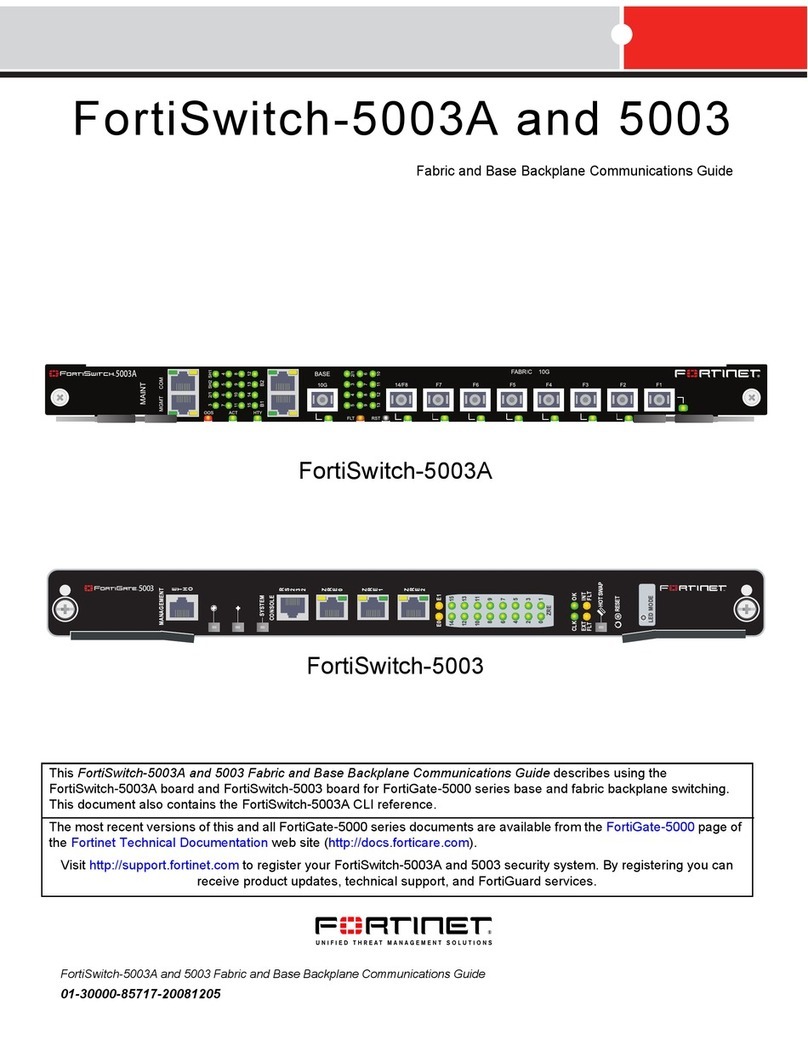
Fortinet 5003A Use and care manual

Fortinet

Fortinet 5003A Use and care manual

Fortinet FortiBridge 3000 Series User manual

Fortinet

Fortinet FortiBridge 3000 Series User manual

Fortinet FortiBridge-2002 User manual

Fortinet

Fortinet FortiBridge-2002 User manual

Fortinet FortiSwitch 248D User manual

Fortinet

Fortinet FortiSwitch 248D User manual

Fortinet FortiGate 40F Series User manual

Fortinet

Fortinet FortiGate 40F Series User manual

Fortinet FortiSwitch-80-PoE User manual

Fortinet

Fortinet FortiSwitch-80-PoE User manual

Fortinet FortiWeb 2000E User manual

Fortinet

Fortinet FortiWeb 2000E User manual

Fortinet FortiSwitch-1000 User manual

Fortinet

Fortinet FortiSwitch-1000 User manual

Fortinet FortiSwitch-5003B Parts list manual

Fortinet

Fortinet FortiSwitch-5003B Parts list manual

Fortinet FortiSwitch Rugged 424F POE User manual

Fortinet

Fortinet FortiSwitch Rugged 424F POE User manual

Fortinet FortiBridge-2002 User manual

Fortinet

Fortinet FortiBridge-2002 User manual

Fortinet FortiSwitch 624F Series User manual

Fortinet

Fortinet FortiSwitch 624F Series User manual

Fortinet Fortinet Switch 800F User manual

Fortinet

Fortinet Fortinet Switch 800F User manual

Fortinet FortiManager 1000D User manual

Fortinet

Fortinet FortiManager 1000D User manual

Fortinet FortiSwitchRugged 112D-POE User manual

Fortinet

Fortinet FortiSwitchRugged 112D-POE User manual

Fortinet FortiSwitch-28C Instruction Manual

Fortinet

Fortinet FortiSwitch-28C Instruction Manual

Fortinet MR1 User manual

Fortinet

Fortinet MR1 User manual

Fortinet FortiSwitch 224D-FPOE User manual

Fortinet

Fortinet FortiSwitch 224D-FPOE User manual

Fortinet FortiSwitch 2048F User manual

Fortinet

Fortinet FortiSwitch 2048F User manual

Fortinet 5003A Parts list manual

Fortinet

Fortinet 5003A Parts list manual

Fortinet FortiManager 3700F User manual

Fortinet

Fortinet FortiManager 3700F User manual

Fortinet FortiSwitch 424E Series User manual

Fortinet

Fortinet FortiSwitch 424E Series User manual

Fortinet FortiSwitchRugged 124D User manual

Fortinet

Fortinet FortiSwitchRugged 124D User manual

Popular Switch manuals by other brands

Cisco SG200 Series Administration guide

Cisco

Cisco SG200 Series Administration guide

Ikan BVS-100 user guide

Ikan

Ikan BVS-100 user guide

Jaycar AC-1707 user manual

Jaycar

Jaycar AC-1707 user manual

Alloy GSS-16T4SFP user manual

Alloy

Alloy GSS-16T4SFP user manual

H3C S5130-28F-EI Configuration guide

H3C

H3C S5130-28F-EI Configuration guide

Omnia OSS8839 manual

Omnia

Omnia OSS8839 manual

Enterasys Mid-Span Power Hub user guide

Enterasys

Enterasys Mid-Span Power Hub user guide

ADC FireWire Patch Panel IEEE 1394a Specification sheet

ADC

ADC FireWire Patch Panel IEEE 1394a Specification sheet

Veris Industries Hawkeye 949 installation guide

Veris Industries

Veris Industries Hawkeye 949 installation guide

ATEN VS-0404 quick start guide

ATEN

ATEN VS-0404 quick start guide

Dynex DX-U27H41 Quick setup guide

Dynex

Dynex DX-U27H41 Quick setup guide

SICK ES21 M12 contact operating instructions

SICK

SICK ES21 M12 contact operating instructions

D-Link DES-3828 - xStack Switch - Stackable datasheet

D-Link

D-Link DES-3828 - xStack Switch - Stackable datasheet

Aaeon FWS-7820 user manual

Aaeon

Aaeon FWS-7820 user manual

Rockwell Automation Allen-Bradley 440G-EZS21STL05J user manual

Rockwell Automation

Rockwell Automation Allen-Bradley 440G-EZS21STL05J user manual

Conrad 97 51 00 operating instructions

Conrad

Conrad 97 51 00 operating instructions

SMC Networks ZSE3 instruction manual

SMC Networks

SMC Networks ZSE3 instruction manual

Sony BRS-200 Operational manual

Sony

Sony BRS-200 Operational manual

manuals.online logo
manuals.online logoBrands
  • About & Mission
  • Contact us
  • Privacy Policy
  • Terms and Conditions

Copyright 2025 Manuals.Online. All Rights Reserved.