Fostex DMT-8VL User manual

Owner's
Manual
postex

A
j
RISK
OF
ELECTROSHOCK
#
■
\
DONOTOPfN_
CAUTION
TO
REDUCE
THE
RISK
Of
ELECTrtC
SMOCK.
00
NOT
REMOVE
COVER
I
OR
BACK)
NO
USER-SERVICEABLE
PARTS
INSIDE.
REFER
SERVICING
TO
QUALIFIED
SERVICE
PERSONNEL
CAUTION:
TO
PREVENT
ELECTRIC
SHOCK.
MATCH
WIDE
Bl
ADC
OF
PLUG
TO
WIDE
SLOT.
FULLY
INSERT
ATTENTION:
POUR
EVITER
LES
CHOCS
ELECTRIOUES.
INTRODUIRE
LA
LAME
LA
PLUS
LARGE
D€
LA
FCHE
DANS
LA
BORNE
CORRESPOND
ANTE
D€
LA
PRISE
ET
POUSSER
AJSOU
AU
FOND
A
T
h#
*]hr*'Q
*
39
*
**r
arrowheed
httM,
wtftn
an
•quwtm
Hin^v
*
ntandad
to
atari
tw
nw
to
toe
prmrKe
o«
u'rauiaietf
*dar«o«rous
.at*;*'
»wr*n
!*•
prcOut}-.
«ncJiiBur«
toe
I
may
be
0
«
Sjmclert
megnllida
lo
comitate
•
n»fc
;/
eiwztn:
tftak
bo
PIMM
The
euUmanxi
peart
■
***•
«n
equfeitrel
Irtingie
a
•rtn-drt
to
8B»n
the
-ser
to
toe
preeerce
a
rnmmni
ocmmng
and
mir-ifr-wce
Itemcwtf
remjctore
ki
the
W-n>Lr«
ecccmpenyno
t*w
ippHrcc
“WARNING"
•TO
REDUCE
THE
RISK
Of
FIRE
OR
ELECTRIC
SHOCK.
DO
NOT
EXPOSE
THIS
APPLIANCE
TO
RAW
OR
MOISTURE
*
SAFETY
INSTRUCTIONS
1
Read
Instruction*
•
Ad
the
safety
and
operating
metruettons
Should
tw
read
t
letor*
toe
applarce
Is
operated
2
Retain
Inalructlooa
-
Tim
safety
and
operabng
mstructcra
ttKhid
be
retained
for
future
reference
3.
Heed
Warnings
-
Ad
on
toe
apptarce
and
in
die
operating
insanicfton*
should
be
adhered
to
4.
Fellow
msaruefons
-
AJI
operalng
and
use
ratfuctkins
sNxAd
be
followed
5.
Wafer
and
Mr.4s.vya
-
Tim
appliance
shoukj
not
be
need
near
wato
fer
example,
near
a
bathfub.
wosttvx*
kitchen
sink
laundry
tub.
in
a
wet
basement,
or
near
a
swimming
pool,
and
the
l*o.
6.
Carls
and
Stands
The
apptarco
should
be
used
only
with
a
cart
or
stand
that
«
rexmenondod
by
the
manufacturer
An
appiiarce
and
cart
combrotton
shoUd
be
moved
with
care
Oufc*
stops,
excess
vo
tore#,
and
uneven
surfaces
may
ceoee
the
appianco
and
cart
combination
to
overturn
7
Wal
or
Ortng
Mounting
-
The
apptarco
should
be
rounted
to
a
wall
or
cehng
only
os
recommended
by
the
manufacturer
8.
Verfclaton
-
The
appliance
shedd
be
stunted
so
to*
its
tocaSon
or
peeiten
dose
not
interfere
wtto
4s
proper
vantlatem
For
ererrpfe,
the
aperture©
srewtt
not
be
stunted
on
a
bod.
sofa.
rug.
or
simlar
surface
that
may
bkxk
the
ventiabon
cperlngs
or,
paced
in
a
bu*-«p
ratal
aticr,
ojeh
as
a
beckcose
or
cabne<
that
may
rpede
the
few
cf
or
through
the
vendaiton
of»nngs
9.
Heal-The
appliance
shoiid
be
situated
away
from
heal
SOSOM
such
as
radiators,
heat
registers,
stoves,
or
other
appliances
(ntfudtog
ampShtrs)
hat
produce
heat
10
Power
Sources
-
The
appliance
shoUd
be
ccmected
to
4
power
supply
orty
oMhe
type
described
n
toe
operating
tosarucecra
or
as
marked
on
the
apprtance.
11.
Grounding
or
Reservation
-
The
precauscra
that
shojd
be
token
so
rat
toe
grojndvig
or
poianzabon
moons
of
an
applorce
ts
not
defeated
12.
Rower
Cord
ProtacSon
-
Power
supply
cords
shouto
be
rcuied
so
toot
toey
are
not
Ikety
to
he
waited
on
or
pnehod
by
Homs
paced
upon
or
agartsr
them,
paying
perfkUar
attention
to
cords
at
pugs,
corweruerxe
receptacle*,
and
the
pore
where
they
ewt
from
the
appliance
13
Cleaning
•
The
oppliarcQ
should
be
cleaned
only
as
recommended
by
the
manufacturer
14
Nonoee
Renods
The
power
aerd
of
the
apptonce
shook!
be
unplugged
from
the
oulet
whan
fe*
unused
lor
a
long
pared
of
Ime
15
Object
and
Uqud
Entry
Care
*kxjM
be
taken
eo
tool
ct*ed*
do
not
te*
and
fcj
uds
art
not
sphod
into
the
andoare
torough
openings
16
Damage
Retiring
Service
-
The
oppureo
should
be
sorveed
by
debited
service
personnel
when
A
The
power
soppy
cord
or
toe
plug
has
been
damn
god,
or
B
Objects
have
falen.
or
tqud
has
been
spdod
into
too
appliance
or
C
The
epptance
has
bean
exposed
to
ran.
or
D
The
applance
does
not
uppw
to
eperatn
neemofry
or
exhibits
a
marked
change
m
performance
or
E
The
appliance
has
been
dropped,
or
too
ondosuro
damaged
17
Servicing
-
The
use-
ttoouto
not
attempt
to
se*vco
the
oppianca
beyond
tool
described
m
the
operaang
ratnxhans
AJI
otoer
servicing
should
be
referred
to
qualAed
service
personnel
Table
of
Contents
Introduction
.6
Precautions
.6
Notes
about
power
supply.6
Notes
on
handling
the
hard
disk.-----7
Notes
on
the
setup
location.—.
7
Notes
on
repair.
8
About
copyrights.---
8
About
damages...—...8
Main
Features
of
DMT-8VL
.9
Names
and
Functions
.
14
Top
panel
(Mixer
section).......14
Top
panel
(Recorder
section)
™
---—--1<>
Front
panel
(1/0
connections)--—.25
Rear
panel
(I/O
connections)...~.—25
Display
section............27
1.
Display
shown
when
the
power
is
turned
on-.-..27
2.
Preset
display--27
3.
Switching
the
display
using
the
DKP
SEL
key---28
4.
Switching
the
Time
Base
display
using
the
EXHT1TE/YES
key
and
DKP
SEL
key.—---29
5.
Changing
Programs
using
the
STORE
key
and
the
HOLD/>
key_JO
6.
Warning
messages.---.——----31
Before
operating
the
DMT-Svl
.
34
1.
Layout
of
the
DMT-8VL
top
panel.----...34
2.
Difference
between
track
and
channel---—.35
3.
Function
of
the
PAN
knob
and
about
the
stereo
bus...35
4.
The
difference
between
a
tapa
based
multitracker
and
a
hard
disk
multitracker.....36
5.
Input
monitor
and
Repro
monitor...
™
--—..—.37
6.
Time
Base-----—38
7.
Effect
Connection.—----39
8.
Installing
the
hard
disk—......-----41
Installing
the
hard
disk
unit
(newly)------42
Replacing
the
another
hard
disk
unit-.43
Formatting
a
hard
disk-
44
Recording/Playback
(Basic
Guide)
.
45
1.
The
default
setting
on
the
DMT-8VI..—45
2.
Basic
analog
data
recording
(before
starting
multitrack
recording).—--
.46
3.
Recording
while
using
the
Program
Change
function
(Switching
Programs
1
-
5)....50
4.
Multitrack
recording
using
overdubbing....52
Step
1:
Recording
a
drum
machine
to
Trade
1.--52
Step
2:
Overdubbing
an
electric
hass
to
Track
2___54
3

Step
3:
Ovcrdlibbing
an
electric
guitar
on
Track
3_.56
Step
4:
Overdubbing
the
vocal
on
Track
4_58
5.
Mlxdown.__...____
60
6.
Digital
Recording
from
an
External
Digital
Device
to
the
DMT-Kvt__
62
7.
Digital
Recording
from
the
DMT-8vt
to
an
External
Digital
Device.
-63
Recording/Playback
(Application
Guide)
.65
1.
Ping-pong
recording.........65
2.
MIDI
Clock
synchronization
system.....67
3.
MTC
Synchronization/Machine
Control
system.
.69
4.
Synchronizing
multiple
DMT-8vt
in
Slave
mode.....72
5.
Using
only
the
recorder
section
on
the
DMT-8
vl
_74
6.
Four-tracks
simultaneous
recording
using
the
digital
recording
function....75
Punch
In/Out
.
76
1.
Auto
Punch
In/Out.
77
Storing
the
Punch
In/Out
point.......
Auto
Punch
In/Out
Rehearsal
mode.
an
Auto
Punch
In/Out
Take
mode___
82
2.
Punch
In/Out
recording
using
a
foot
switch.
Punch
In/Out
Rehearsal...
R4
Punch
In/Oul
Take....
as
Locate
function
.
M7
1.
Locate.—-.-...
87
2.
Auto
Play
mode.
HR
3.
Auto
Return
mode——.___„
HR
Setting
the
Auto
Return
Surt/End
point__
4.
Auto
Repeat
mode....
.
-89
.92
Edit
function
.
Q?
1.
Copy
&
Paste.
04
Copying.
Qi
Copy
&
Pasting.....
q*
2.
Move
&
Paste.
99
Moving....
Move
A
PastimL—._
..99
ini
3.
Erased
Cut....
tru
Erasing.
10
s
Cutting...
106
Setup
mode
.
1.
Entering
Setup
mode...
2.
Setting
the
time
signature
("BAR/')___
3.
Tempo
setting
("TEMPO")..
4.
Metronome
function
On/Off
(-CLICK"
ON/OFF).
.
108
.108
.113
-.114
.116
5.
Saving
and
loading
the
recordings
("SAVE",
"LOAD”)
..117
6.
Formatting
the
hard
disk
("FORMAT')_
-123
4
7.
Setting
the
preroll
time
for
the
locate
operation
('PRliROLLTIME")....124
8.
Selecting
the
synchronized
signal
output
from
the
MIDI
OUT
connector
("MIDI
SYNC
OUT").
™
—
™
..125
9.
Setting
the
MTC
frame
rate
("FRAME
RATE")....126
10.
Setting
MTC
offset
time
("MTC
OFFSET")...«...-127
11.
Setting
recording
Enable/Disable
mode
("rEc"
ENABLE/DISABLE)..128
12.
Setting
a
digital
input
channel
CdG
in")--129
13.
Setting
a
digital
output
channel
("dG
out")...—
131
14.
Setting
display
resolution
mode
On/Off
("rESoLu/").„
™
,.
™
.132
15.
Setting
Slave
mode
On/OfF
("SLAVE")—...-.........-—133
16.
Setting
MIDI
device
ID
<"dEVicE")---134
17.
Setting
the
Undo
function
range
("Undo”)—
™
~..—,..135
MIDI
Implementation
Chart
.
1
36
MMC
command
list
.
137
Inquiry
Message
list
.
137
Fostex
MIDI
System
Exclusive
Message
Format
.
1
38
Maintenance
.
14&
Specifica
tions
.
1
4
&
Block
Diagram
.
130
INDEX
.
131
5

DMT
■
8vl
Owner's
Manual
(Introduction)
Introduction
Thank
you
for
purchasing
the
Fostex
Model
DMT-8VL!
The
DMT-8VL
Is
an
eight-track
digital
multitrack
recorder
with
an
integrated
eight-channel
analog
mixer
and
a
dedicated
E-IDE
type
Internal
hard
disk
system.
It
enables
you
to
achieve
high-quality
recording/playback
using
a
non-compression
recording
method,
with
a
quantization
of
16
bits
and
a
sampling
rate
of
44.1
kHz.
which
is
approximately
equivalent
to
CD
quality.
The
DMT-8VL
incorporates
many
advanced
functions
thanks
to
the
Inclusion
of
a
hard
disk,
such
as
copy
&
paste,
move
&
paste,
cut.
erase
(using
time
value
or
MIDI
bar/beat/dock),
and
undo/redo.
Once
standard
hard
disk
can
manage
up
to
live
programs
(Program
Clhange
function),
and
you
can
record,
play
back,
edit,
and
archives
(save
and
load)
each
Program.
The
DMT-8VL
is
also
equipped
with
a
Jog
wheel
and
a
shuttle
dial
for
speedy
operation,
a
song
data
save/load
function
for
use
with
an
external
DAT
recorder,
and
an
AUTO
function
that
includes
9-point
AUTO
locate,
AUTO
return/play,
and
AUTO
punch
In/out
(with
rehearsal
function).
The
unit
can
also
transmit
MIDI
clock
data
and
Song
Position
Pointers
via
the
internal
programmable
tempo
map,
and
is
compatible
with
MTC,
MMC,
and
Fostex
System
Exclusive
Message.
You
can
also
control
and
synchronize
an
external
MIDI
sequencer
or
sequencing
software
from
the
DMT-8
vl
Please
read
this
Owner's
Manual
thoroughly
and
keep
it
in
a
safe
place
so
that
you
will
be
able
to
produce
high-definition,
high
tonal
quality
music.
Precautions
Notes
about
power
supply
*
Be
sure
to
connect
the
DMT-8VL
to
the
power
supply
specified
in
the
Specifications
section
of
this
Owner's
Manual.
Do
not
use
an
AC
outlet
of
any
other
voltage.
*
Do
not
connect
the
DMT-8VL
to
the
same
AC
outlet
to
which
devices
that
could
generate
noise
(such
as
a
large
motor
or
dimmer),
or
the
devices
that
consume
a
large
amount
of
power
(such
as
an
air
conditioning
system
or
a
large
electric
heater)
are
connected.
*
If
you
use
the
unit
In
an
area
with
a
different
power
voltage,
first
consult
your
dealer
or
the
nearest
FOSTEX
service
station.
You
can
use
the
unit
with
a
power
frequency
of
50Hz
or
60Hz.
*
It
is
very
dangerous
to
use
a
power
cord
that
Is
frayed
or
damage.
In
such
a
case,
stop
using
the
unit
immediately
and
ask
your
dealer
to
repair
the
cord.
*
To
avoid
possible
electric
shock
and
damage
to
the
DMT-8
vl,
avoid
contact
with
water
or
other
liquids,
or
do
not
handle
the
power
plug
while
your
hands
are
wet.
6

DMT-8vl
Owner's
Manual
(Introduction)
*
To
prevent
possible
electric
shock
and
damage
to
the
DMT-Svl,
do
not
remove
the
main
unit
cover
or
reach
the
inside
the
unit.
*
Do
not
let
water
or
other
liquid,
or
metal
objects
such
as
pins,
accidentally
enter
the
inside
of
the
unit
because
this
may
lead
to
electric
shock
or
damage.
Should
water
enter
the
inside
of
the
unit,
remove
the
power
plug
from
the
AC
outlet,
and
consult
your
dealer
or
the
nearest
FOSTEX
service
station.
*
To
prevent
damage
to
the
DMT-Svl,
be
sure
to
power
on
the
connected
devices
first,
then
turn
on
the
power
to
the
DMT-8VL.
When
you
remove
or
connect
the
cables
to
the
input/output
connectors
on
the
DMT-8VI,
make
sure
that
the
channel
INPUT
faders
and
volume
controls
are
set
to
"0."
Notes
on
handling
the
hard
disk
*
The
DMT-8vi
is
equipped
with
a
high-precision
hard
disk.
Do
not
expose
the
unit
to
excessive
vibration
at
any
time.
In
particular,
do
not
move
the
unit
or
allow
an
impact
to
the
unit
when
the
power
is
on.
*
Bfilore-lurning
the
power
first
auitEetup
mode
and
make
sure
that
the
recorder
scctlon
is
stopped.
Especially,
nev
er
attemp
t
to
turn
off
the
power
to
the
unit
while
the
hard
disk
Is
accessing
dau
(the
HD
.ACCES
S
LE
D
i
s
lit
or
flashing).
Otherwise,
hot
only
will
you
lose
recorded
data,
but
you
m
ay
damage
to
the
unit.
FOSTEX
is
not
responsible
for
data
lost
during
operation
of
the
unit.
*
Before
you
change
the
location
of
the
DMT-8
vl,
pack
the
unit
in
the
shipping
carton
or
an
impact-resistant
case.
Make
sure
that
the
unit
is
kept
free
from
external
vibration
or
impact
since
the
unit
is
very
sensitive
to
vibration.
•
U
you
wish
to
replace
the
included
hart
dts*
w4h
another
harddisk.
refer
to
ftofor*
operating
the
DMT
-flw.'
on
page
'41.
‘
Notes
on
the
setup
location
*
Do
not
Install
the
unit
in
locations
subject
to
the
following:
*
Extremely
high
or
low
temperature,
or
significant
changes
in
temperature
*
Excessive
humidity
or
dust
*
Excessive
changes
in
power
supply
voltage
*
Unstable
or
significantly
vibrating
or
shaking
surfaces
*
Near
a
strong
magnetic
field
(such
as
a
TV
or
speakers)
*
If
you
move
the
unit
from
a
place
with
an
excessively
low
temperature
to
a
warm
place,
or
if
you
use
the
unit
in
a
room
in
which
the
temperature
varies
significantly
during
winter,
condensation
may
occur
on
the
hard
disk
or
other
pans.
In
such
cases,
leave
the
unit
for
about
an
hour
in
the
new
location
before
you
turn
on
the
power.
7
DMT-8VL
Owner's
Manual
(Introduction)
Notes
on
repair
*
This
unit
does
not
use
any
pans
that
users
can
repair
easily.
Contact
your
dealer
or
the
nearest
FOSTEX
service
station
to
ask
about
repairs.
*
Use
the
packing
carton
designed
for
the
DMT-8VL
when
you
transport
the
unit
to
the
dealer
for
repair
or
return.
If
you
have
discarded
the
packing
box,
try
to
pack
the
unit
completely
using
shock
absorbing
materials.
Fostex
is
not
responsible
for
malfunction
or
damage
due
to
Incomplete
packaging
or
caused
during
transport.
About
copyrights
*
It
is
prohibited
by
law
to
use
any
part
of
a
CD
recording
or
video
images
or
audio
data
for
which
copyright
is
possessed
by
a
third
party
for
commercial
purposes
such
as
contents,
broadcasts,
sales,
or
distribution
-
any
purpose
other
than
for
your
personal
pleasure.
About
damages
*
Fostex
is
not
responsible
for
any
"direct
damage"
or
"indirect
damage"
caused
by
using
the
DMT
8vu
8

DMT-Svi
Owner's
Manual
(Main
features
of
DMT-8VL)
Main
Features
of
DMT-8
vl
The
DMT-8
vl
Is
equipped
with
the
following
functions:
<Recorder
Section>
High-quality
sound,
non-compressed,
eight
track
digital
hard
disk
recorder
*
Instead
of
conventional
cassette
tape,
the
DMT-Svl
Is
equipped
with
a
dedicated
3.5
inch
fc
lDfc
t>pe
hard
disk
as
the
recording
media,
allowing
for
about
12
minutes
(when
installing
the
540MB
hard
disk
unit)
or
about
30
minutes
(when
installing
the
1.3GB
hard
disk
unit)
of
recording/
playback.
*
Non
compression
recording
method,
with
16-blt
linear
quantization
and
a
sampling
rate
of
44.1kHz,
which
enables
you
to
record
and
playback
high
quality
sounds
that
are
approximately
equivalent
to
CD
quality.
Managing
up
to
five
programs
using
the
Program
Change
function
*
Using
the
Program
Change
function
allows
you
to
record,
playback,
and
edit
up
to
five
songs
individually
on
the
hard
disk.
In
this
way,
you
can
utilize
the
hard
disk
to
manage
different
programs
at
any
time,
without
the
necessity
of
archiving
(backing
up)
data
to
an
external
DAT
machine.
(Refer
to
pages
*36"
and
"50’
for
more
details.)
Versatile
editing
functions
are
made
possible
by
the
hard
disk
*
The
DMT-Svi.
allows
you
to
use
non-linear,
non-destructive
audio
editing
functions,
such
as
copy
&
paste,
move
&
paste,
cut,
and
erase.
These
edit
operations
can
refer
not
only
to
time
values
such
as
ABS
and
MIDI
timecodc.
but
to
MIDI
bar/bcat/dock
values.
(Refer
to
page
"93"
for
details.)
*
You
need
only
one
action
to
monitor
the
copied
audio
data
using
the
Clipboard
Play
function.
(Refer
to
pages
"96"
and
’101"
for
details.)
*
The
Over
Time
Monitor
function
lets
you
know
the
overtime
length
when
you
try
to
copy
&
paste
or
move
*
paste
data
in
excess
of
the
currently-available
disk
space.
(Refer
to
page
"31"
for
details.)
Undo/Redo
function
to
support
edit
works
*
The
Undo/Redo
functions
will
cancel
the
latest
edit
and
restore
the
data
obtained
before
the
edit,
or
restore
the
data
obtained
after
the
edit
respectively.
(Refer
to
pages
"82,
98.
103,
106
and
107"
for
details.)
*
The
Can't
Undo
function
provides
you
with
an
alarm
indicating
that
the
undo
area
is
insufficient
for
the
Auto
Punch
In/Out
operation.
(Refer
to
page
"31"
for
details.)
Song
data
SavefLoad
function
*
You
can
save
recordings
(audio
data
plus
corresponding
setup
data)
of
each
Program
individually
or
all
Programs
simultaneously
to
an
external
DAT
machine.
You
can
also
load
a
set
of
data
to
a
desired
Program.
9

DMT-8vi
Owner's
Manual
<Main
features
of
DMT-8
vl)
The
Save/Load
function
will
take
about
four
times
as
long
as
recording
(l.e.,
it
takes
16
minutes
to
save
or
load
a
four-minute
song).
(Refer
to
page
”117"
for
more
details.)
Convenient
Disk
Remain
Display
function
*
The
Disk
Remain
function
facilitates
checking
the
available
recording
time.
This
function
is
compatible
with
all
types
of
time
references
-
ABS,
MTC,
MIDI
bar,
and
beat.
Three
types
of
time
reference
*
The
10
digit.
7
segment
display
shows
the
current
time
(position)
of
the
recorder
using
ABS
time,
MTDI
timecode,
or
MIDI
bar/beat.
*
ABS
and
MTC
function
with
sub-frame
precision
(1/100
frame),
and
the
MIDI
bar/beat
is
96
clock
precision.
These
arc
used
for
data
display
and
the
memory
register.
Various
Auto
functions
*
The
DMT-8VL
is
equipped
with
six
time
memories
that
can
be
edited.
Using
these
memories,
you
can
perform
auto
locate,
auto
return
and
auto
play
between
two
points,
and
auto
punch
in/out
(crossfade
time:
10ms).
(Refer
to
pages
"77"
and
"87"
for
more
details.)
*
Auto
locate
to
ABS
0
or
ABS
END
is
also
possible.
In
addition,
the
LOCATE
key
has
its
own
memory.
This
is
very
useful
for
a
repeated
locate
operation.
(Refer
to
page
"87"
for
more
details.)
*
There
are
two
modes
for
Auto
Punch
In/Out
function:
"Take"
mode,
which
is
used
for
actual
recording,
and
'Rehearsal,"
which
is
used
to
switch
the
part
located
between
the
In
and
Out
points
to
the
Input
monitor.
(Refer
to
page
"77"
for
more
details.)
*
The
Pre-roll
function
is
used
to
"park"
a
specified
time
prior
to
the
locate
point.
Pre-roll
time
can
be
set
in
the
range
of
0
-
10
seconds.
(Refer
to
page
"124"
for
more
details.)
MIDI
function
using
MMC,
MTC,
and
Fostex
System
Exclusive
Message
*
You
can
add
an
offset
of
less
than
six
hours
to
the
ABS
time
value
to
output
MTC
(MIDI
timecode).
The
MTC
frame
rate
is
compatible
with
all
formats
-
24,
25,
30DF,
and
30ND.
(Refer
to
page
"126”
for
setting
the
frame
rate,
and
to
page
"127"
for
setting
the
offset
time.)
*
The
DMT-8
vl
responds
to
MMC
(MIDI
Machine
Control)
and
Fostex
System
Exclusive
Message
sent
from
external
sequencing
software.
(Refer
to
pages
"67,
70
and
137”
for
more
detaiLs.)
Syncing
multiple
DMT-8
vls
by
the
Slave
Sync
function
*
The
Slave
Sync
function
allows
you
to
operate
multiple
DMT-8
vls
in
synchronization,
creating
more
than
8
to
24-track
recording
system.
(Refer
to
page
*72”
for
more
details.)
10

DS1T-8vl
Owner's
Manual
(Main
features
ofDMTSvi)
Internal
programmable
Tempo
Map
*
The
DMT-8
vl
is
equipped
with
an
Internal
programmable
Tempo
Map
that
allows
the
MIDI
clock
and
Song
Position
Pointer
to
be
transmitted
to
an
external
sequencer
iswitchablc
to
MTC
output)
for
complete
synchronization
with
a
hardware
sequencer.
You
can
also
use
Track
8
as
a
Metronome
playback
track,
which
will
generate
counts
according
to
a
Tempo
Map.
(Refer
to
pages
’113'
-
"116"
for
more
details.)
*
Eleven
types
of
Tempo
Map
signature
are
available:
1
/4,
2/4,
3/4,4/4,
5/4,
1/8,
3/8,
5/8,
6/8,
7/8,
and
8/8.
Maximum
64
points
of
signature
can
be
set.
*
Up
to
64
points
of
tempo
on
a
Tempo
Map
can
be
set
on
any
point
determined
by
the
signature
settings,
in
the
range
of
30
-
250
per
quarter
note.
(Refer
to
page
"114*
for
more
details.)
Setup
Menu
function
*
The
DMT-8VL
is
equipped
with
the
following
setup
Menu
functions
for
the
interactive
operation
system.
You
can
use
a
highly
visible
FL
tube
display
and
the
jog/shultle
dial
to
set
the
parameters.
(Refer
to
page
"108"
for
more
details.)
Mein
Setup
Menu
LOAD
(loading
audio
and
setup
data)
(Refer
to
page
"fir
for
details.)
SA
VE
(saving
audio
and
setup
data)
(Refer
to
page
’117"
lor
details
)
FORMA
T
(formatting
the
internal
hard
dtskj
(Refer
to
page
’123'for
details.)
PREROLL
(setting
the
Pre-roll
time)
(Refer
to
page
‘124‘for
details.)
MIDI
SYNC
OUT
(selecting
UTC.
MIDI
clock,
or
OFF)
(Refer
to
page
'125'
for
details
)
FRAME
RATE
(setting
the
MTC
frame
rate)
(Refer
to
page
•
126'
for
details.)
MTC
OFFSET
(setting
the
MTC
offset
value
against
the
A0S
time)
(Refer
to
page
'127~
lor
dated*)
BAR/BEAT
SET
(setting
the
signature)
(Refer
to
page
'113'
for
details.)
TEMPO
SET
(setting
the
tempo)
(Refer
to
page
'114'
for
details
)
CLICK
ON/OFF
(switching
the
Metronome
function
ON/OFF)
(Refer
to
page
'118'for
details.)
REC
ENABLE
(setting
the
RFC
ENABLE
or
RFC
DISABLE)
(Refer
to
page
'128'
for
defats.)
dO
fn
(selecting
a
digital
input
channel)
(Refer
to
page
'
129'
for
details
)
dO
out
(selecting
a
mg
W
output
channel)
(Refer
to
page
'131'for
details.)
rESoLu
(setting
Display
Resolution
mode
ON/OFF)
(Refer
to
page
'132'
for
details
)
SLAvE
(sotting
Slave
mode
ON/OFF)
(Refer
to
page
'13T
for
dotard.)
dEvIcE
(setting
a
demco
10)
(Refer
to
page
'134'
for
details.)
undo
(setting
an
affective
range
of
the
Undo
function)
(Refer
to
page
'135'
for
details
)
Easy-to-use
jog/shuttle
dial
*
Using
the
shuttle
dial
allows
for
+/-1,
2,
3,
5,
9,
12.
or
20
time
speed
cueing
(fast-forward
while
monitoring
audio).
*
Using
the
jog
dial
allows
for
digital
audio
scrubbing.
Using
this
function,
you
can
locate
data
efficiently
while
monitoring
audio
without
any
changes
in
pitch.
*
The
jog/shuttle
dial
is
also
used
to
recall
parameters
and
to
enter
data.
11
DMT-8VL
Owner's
Manual
(Main
features
of
DMT-8
vl)
Other
recorder
functions
*
In
addition
to
30-time
speed
FF/REW,
5-time
speed
cueing
(PLAY+FF/
REW)
is
also
available.
*
Connect
an
optional
foot
switch
Model
8051
to
the
PUNCH
IN/OUT
connector
for
punch
In/out
(and
rehearsal)
operation
to
free
your
hands.
(Refer
to
page
"83"
for
more
details.)
*
A
highly
visible
FL-tube
level
meter
shows
the
output
level
of
Tracks
1-
8
and
STEREO
OUT
L/R.
*
The
DMT-8
vl
can
record
data
digitally
to
and
from
an
external
digital
device.
<Mlxer
Section>
A
high-quality
eight-channel
analog
mixer
that
offer*
two
microphone
Input*,
and
mixdown
of
a
maximum
20
channels
*
The
DMT-8VI
is
equipped
with
a
high-quality
eight-channel
analog
mixer
with
eight
inputs
Including
two
for
microphones.
*
Channels
1-2
for
microphones
are
equipped
with
a
LEVEL
switch
for
selecting
-lOdBV,
-
30dBV,
or
-50dBV,
depending
on
the
connected
sound
sources
and
microphones.
*
The
stereo
input
monitor
section
allows
for
remixing
with
the
main
stereo
L/R
signal,
which
simulates
virtual
16-channel
(maximum
20-channel)
mixing.
(Refer
to
page
"69"
for
more
details.)
*
The
Inline
monitor
section
allows
you
to
select
any
output
for
the
input
or
track.
This
powerful
feature
is
very
useful
in
various
applications,
such
as
virtual
mixing
of
MIDI
sound
sources
and
effect
pre-sending.
*
The
stereo
L/R
output
can
be
routed
to
the
DATA
OUT
connectors
(optical,
S/P
DIF
format).
Flexible
two
AUX
send/return
*
Each
input
channel
has
two
AUX
sends.
Along
with
two
stereo
AUX
returns,
versatile
effects
processing
is
possible.
(Refer
to
page
"39"
for
more
details.)
Other
mixer
functions
*
MON
OUT
connector
and
MONITOR
volume
for
audio
monitoring
through
the
amplifier
or
speakers.
*
The
monitor
section
Is
equipped
with
a
selector
that
allows
you
to
monitor
the
stereo
L/R
output
signal
and
the
monitor
signal
either
individually
or
simultaneously.
12

DMT-8vl
Owner's
Manual
(Names
and
Functions)
Roar
panel
section
(Refer
to
page
*25"
(or
(Walls.)
Front
panel
section
(Refer
to
page
*25*
»or
details.)
3
DMT-8vl
Owner's
Manual
(Names
and
Functions)
Names
and
Functions
<Top
panel
(Mixer
section)>
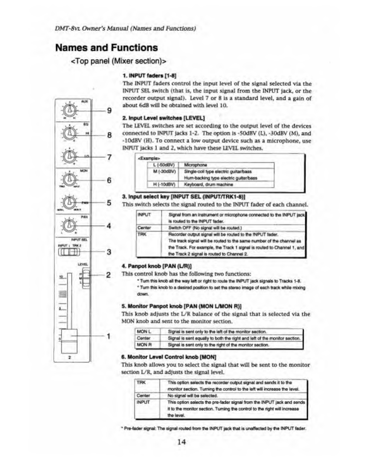
1.
INPUT
fader*
£1-B]
The
INPUT
fader*
control
the
input
level
of
the
signal
selected
via
the
INPUT
SFl
switch
<that
Is,
the
input
signal
from
the
rNPUT
Jack,
or
the
recorder
output
signal).
Level
7
or
8
Is
a
standard
level,
and
a
gain
of
about
6dB
will
be
obtained
with
level
10.
2.
Input
Level
switches
[LEVEL]
The
LEVEL
switches
are
set
according
to
the
output
level
of
the
devices
connected
to
INPUT
jacks
1-2.
The
option
is
-50dBV
(L),
-30dBV
(M),
and
-lOdBV
<H).
To
connect
a
low
output
device
such
as
a
microphone,
use
INPUT
Jacks
1
and
2,
which
have
these
LEVEL
switches.
<Ejoerp4e>
j
M-eodftV)
M
|
30dBV)
Microphone
Snglo
cell
type
electoc
guter.toa&s
Murr-bacfcng
type
afectnc
g
iMaM
HMOdBV)
Keyboard.
dru-ti
machine
3.
Input
select
key
[INPUT
SEL
(INPUT/TRK1-6))
This
switch
selects
the
signal
routed
to
the
INPUT
fader
of
each
channel.
lird’UT
5
gr*i
from
an
<c#tr\jnerri
or
rWcrophcn#
corrected
to
toe
INPUT
yack
la
routed
to
toe
INPUT
tod*
Carter
Swtch
OFF
(No
*gna!
w4t
t*
routed)
TRK
4.
Panpot
knob
(PAN
(UR)]
This
control
knob
has
the
following
two
functions:
•
Turn
Ihi
knot
all
toe
way
loft
or
right
to
route
the
IN
KIT
|ar*
signals
to
Tracks
1-8.
•
Turn
tfvs
knob
to
a
desired
position
to
aat
toe
stereo
image
of
each
track
while
miikig
down.
5.
Monitor
Pan
pot
knob
[PAN
(MON
L/MON
R)]
This
knob
adjusts
the
L/K
balance
of
the
signal
that
is
selected
via
the
MON
knob
and
sent
to
the
monitor
section.
MON
L
S-gral
is
sent
only
to
too
mfl
oi
too
monitor
sectcn
Carter
S-gral
is
sent
aqualy
to
both
toa
right
and
loft
of
ttio
mentor
section.
MON
R
Signal
n
sent
only
to
toa
r^pit
of
the
rrerttof
section.
6.
Monitor
Level
Control
knob
[MON]
This
knob
allows
you
to
select
the
signal
that
will
be
sent
to
the
monitor
section
L/R.
and
adjusts
the
signal
level.
1
TRK
The
option
sweets
toa
recorder
culpa
signal
arid
sands
it
to
too
mentor
section
7
umrg
toe
corteol
to
too
left
iwl
ncronse
too
level.
Canter
INPUT
No
signal
w*
be
selected.
The
opbon
selects
too
protedor
signal
Vom
the
WPUT
|ack
and
sends
H
to
the
monitor
soctcc
7umng
the
conM
to
toe
right
wiV
increase
the
lev*.
*
Pre
fedar
sgrai:
The
signal
routed
from
too
INPUT
jack
that
is
Lnatlected
by
toe
INPUT
fader
14

DMT-Svl
Owner's
Manual
(Names
and
Functions)
7.
L
ow
Equalize
Gain
Control
knob
[EQ
LO]
This
knob
is
used
to
boost
or
cut
the
frequency
of
100Hz
in
the
range
of
*/-15dB.
8.
High
Equalizer
Gain
Control
knob
[EQ
HI]
This
knob
is
used
to
boost
or
cut
the
frequency
of
10kHz
in
the
range
of
♦
/-15dB.
9.
AUX
Send
knob
[AUX]
This
knob
Is
used
to
select
whether
the
signal
at
the
INPUT
fader
Is
routed
to
the
AUX
SEND
1
or
to
the
AUX
SEND
2
jack,
and
to
adjust
the
send
level.
Once
selected
and
adjusted,
the
signal
is
sent
from
the
AUX
SEND
jack
to
a
connected
external
device
such
as
an
effect
unlL
At
Setec«ng
to*
option
«N
caueo
mo
ft
gnat
to
bo
muted
to
too
AUX
SENO
1
jock.
Rctedng
ttw
knob
ctockwtta
vwli
incroas#
the
send
level
center
No
ntyru*
bo
output.
A2
Selecting
to*
option
Ml
cause
Via
sgnai
to
bt
roofed
to
V*
AUX
SEW
2
jack.
RcfeOng
tfa
knob
oounter-clockwise
w*
»nc
r*«e
V*
Mod
lava!
10.
Master
fader
[L/R]
This
fader
adjust
the
output
signal
level
at
the
STEREO
OUT
L/R
jacks
(Stereo
Bus
L/R
output
signal).
The
settings
will
also
affect
the
level
of
the
signal
routed
to
the
recorder,
and
the
output
level
from
the
monitor
section.
11.
Monitor
selector
[SELECTOR
(UR.
L/R+MON,
MON)]
This
switch
allows
you
to
select
the
signal
output
at
the
MON
OUT
L,
R.
and
PHONES
jack.
UR
Thu
option
salt
icts
Via
signal
output
from
tha
8TEREO
OUT
UR
1
lack*
{stereo
to*
UP
signal
|.
I
“UTWMON
Ttea
option
soli
ids
boto
to#
®grW
ou*xX
*om
INe
STEREO
OUT
1
UR
|ntxs
and
tha
signal
routed
to
Via
channel
montic*
bus
UR
MON
TTm
option
tali
UR.
ids
V*
signal
routed
to
toe
channel
monitor
bus
12.
Monitor
Master
Laval
knob
[MASTER)
This
knob
adjusts
the
final
monitoring
volume
level.
Using
this
knob
will
affect
the
level
of
the
headphones
volume
and
the
signal
output
from
the
MON
OUT
lacks
l/R.
13.
AUX
Raturn
2
Laval
control
[AUX
RTN
2]
This
control
adjusts
the
signal
level
Input
from
an
effect
unit
connected
to
the
AUX
RTN
2
jack.
The
volume
level
changes
equally
for
the
L
and
R
channels.
14.
A
UX
Raturn
1
Laval
control
[AUX
RTN
1]
This
control
adjusts
the
signal
level
Input
from
an
effect
unit
connected
to
the
AUX
RTN
I
jack
The
volume
level
changes
equally
for
the
L
and
R
channels.
15

DMT
8vl
Owner's
Manual
(Names
and
Functions)
<Top
panel
(Recorder
section)>
15.
Meter
display
This
meter
display
shows
the
signal
level
and
settings.
16.
Record
Track
Select
key
[RECORD
TRACK]
The
Record
Track
Select
key
selects
"SAFE-READY”
for
the
recording
track.
When
you
press
this
key
once,
the
track
enters
the
READY
status,
and
the
track
Indication
on
the
display
will
blink.
Pressing
it
again
changes
this
status
to
"SAFE"
and
the
track
indication
will
go
out.
When
you
start
recording,
the
blinking
track
indication
becomes
illuminated.
When
you
press
only
the
RECORD
button
while
the
track
is
in
the
READY
status,
the
track
becomes
an
input
monitor,
allowing
you
to
adjust
the
recording
level.
Pressing
only
the
RECORD
button
again,
the
track
become
a
reproduction
monitor.
This
key
is
also
used
to
select
a
track
for
the
Copy
&
Paste,
Move
&
Paste,
Erase,
or
other
editing
operation.
;
"
Rtfr
lo
paga
*37*
tor
flata#a
about
f
prodjetoon
monitor
an
J
N
input
man
nor
J
16
DMT-8VL
Owner's
Manual
(Names
and
Functions)
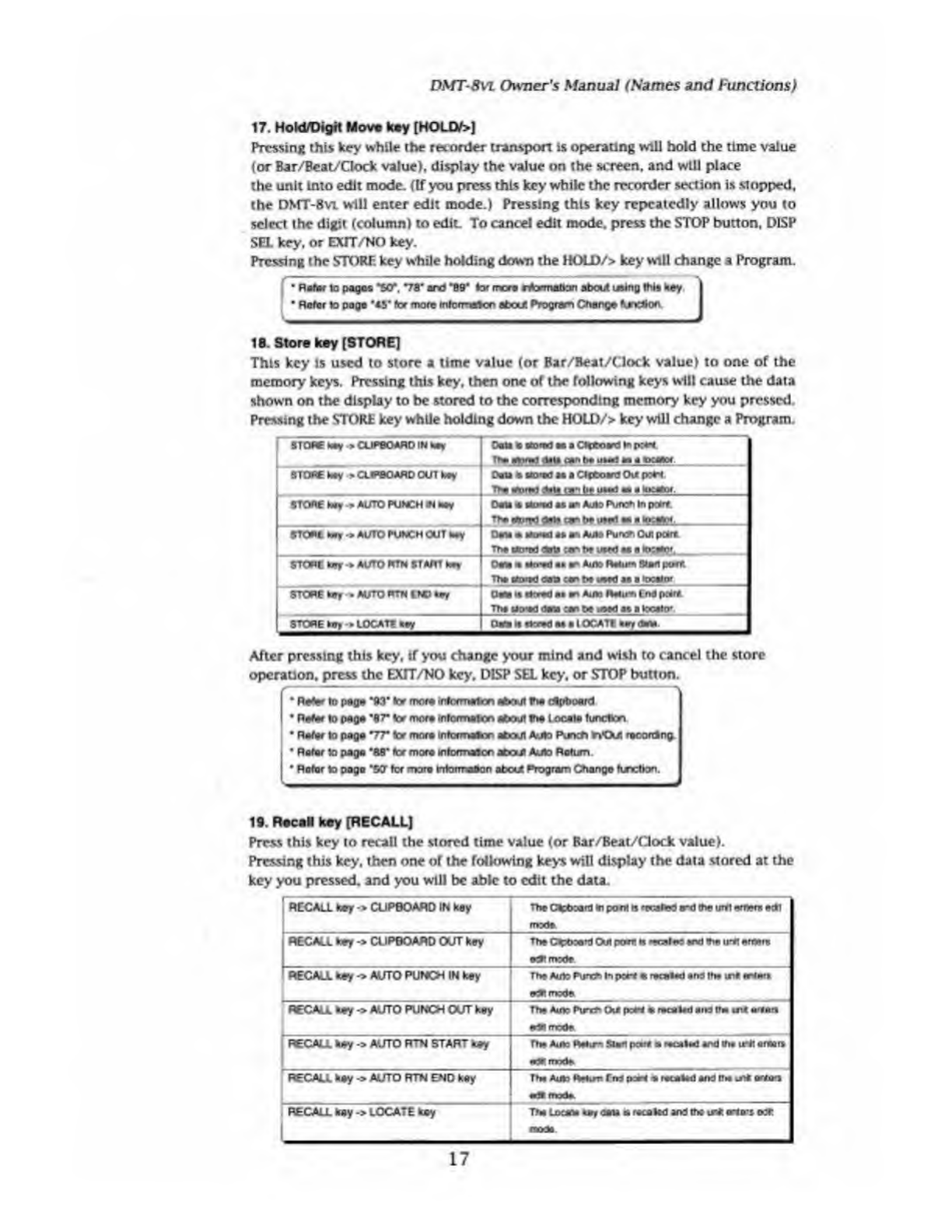
17.
H
old/Digit
Move
key
[HOUY>J
Pressing
this
key
while
the
recorder
transport
is
operating
will
hold
the
time
value
(or
Bar/Bcat/Clock
value),
display
the
value
on
the
screen,
and
will
place
the
unit
Into
edit
mode.
(If
you
press
this
key
while
the
recorder
section
is
stopped,
the
DMT-8
vl
will
enter
edit
mode.)
Pressing
this
key
repeatedly
allows
you
to
select
the
digit
(column)
to
edit.
To
cancel
edit
mode,
press
the
STOP
button,
DISP
SEL
key,
or
EXIT/NO
key.
Pressing
the
STORK
key
while
holding
down
the
HOLD/>
key
will
change
a
Program.
•
Rafor
to
pages
*50*.
*78*
and
‘B9*
lor
mere
rformatton
about
using
this
hey
I
•
Rater
to
poga
#
45*
ter
more
mtormanen
about
Program
Change
kjnedon
18.
S
tore
key
[STORE]
This
key
is
used
to
store
a
time
value
(or
Bar/Beat/Clock
value)
to
one
of
the
memory
keys.
Pressing
this
key,
then
one
of
the
following
keys
will
cause
the
data
shown
on
the
display
to
be
stored
to
the
corresponding
memory
key
you
pressed.
Pressing
the
STORE
key
while
holding
down
the
HOLD/>
key
will
change
a
Program.
STORE
hay
■
>
CUPBOARD
IN
hay
Dan
la
fl'D'td
ao
a
CHboard
to
p:*i
Urn
g
data
aan
to
uua
a*
a
moot
STORE
hay
>
CLIPBOARD
OUT
koy
Oeta
a
Bored
as
a
Clpboard
Out
port
TH?
riirwl
Alla
r»n
to
him!
a*,
a
STORE
koy
•>
AUTO
PUNCH
iN
hay
Oaia
«
u
o*
ad
as
an
Auto
Pure*
In
potrt.
Tto
ate*tfl
data
&
to
Art
•«
a
h*aS>r_
STC*t
tory
•*
AUTO
PUNCH
OUT
hay
Oaia
*
*o*d
as
an
Auto
Pure*
Oui
poire
The
cto'td
dots
:r
to
uwd
aa
a
locator,
STORE
toy
*
AUTO
RTN
START
hay
Ocm
m
a*n-ad
as
an
Auto
Ralum
Start
port
Tha
ktoiad
etna
ran
to
uaad
as
a
locator
STORE
toy
»
AUTO
RTN
END
Clara
it
Breed
aa
an
Auto
Ratum
End
peart
Tha
uo'Kl
<:aa
.ar
to
t^ed
as
a
tocato*
STORE
toy-»
LOCATE
toy
(Mi
it
Breed
aa
a
IOCAT1
After
pressing
this
key,
if
you
change
your
mind
and
wish
to
cancel
the
store
operation,
press
the
EXTT/NO
key,
DISP
SEL
key,
or
STOP
button.
•
Rater
to
page
“93*
ter
more
toformaicn
about
the
dlpboerd
•
Rater
to
page
*87"
lor
more
inlormafco
afeoul
the
Locale
function
•
Rater
to
paga
V7*
ter
more
informaton
about
Auto
Runet)
nOi
racorOIng.
I
•
Rater
to
paga
'88*
tor
mora
mtormaicn
about
Auto
Return
•
Rotor
to
pogo
"5CT
ter
mora
tntorrraOon
atcut
Program
Change
function.
19.
R
tcaN
key
[RECALL]
Press
this
key
to
recall
the
stored
time
value
(or
Bar/Beat/Gock
value).
Pressing
this
key.
*hen
one
or
the
following
keys
will
display
the
data
stored
at
the
key
you
pressed,
and
you
will
be
able
to
edit
the
data.
'
RECALL
toy
->
CUPBOARD
IN
k
B
y
The
CteboanJ
to
pant
n
'iwlrt
rxt
toe
uret
entor*
edl
mode
RECALL
key
->
CUPBOARD
OUT
key
The
Ctehoant
Out
prert
n
••r.iir
«nd
toeirrt
erttoce
ecRmrete
RECALL
key
->
AUTO
PUNCH
IN
key
Tha
Auto
Pun*»
In
port
*
recalad
and
tto
wn«
enters
reBt
mode
RECALL
key->
AUTO
PUNCH
OLfT
key
l-
-
:
:-
—-
Tha
Auto
Pure*
0\*
po*i
a
recalad
end
(ha
urt
mrtmrt
edBmode
RECALL
hay
-»
AUTO
RTN
START
toy
•P
nwde
RECALL
hay
->
AUTO
RTN
END
key
Tha
Auto
RBun
Tito
poa*
s
recalad
and
if*
re*
orto*i
«
■
!»
imh.
.
RECALL
hay
->
LOCATE
hay
Tha
locum
u
r
data
a
recakd
and
the
re*
ario-s
o:r
mod*
17

DMT-8VL
Owner's
Manual
(Names
and
Functions)
To
exit
edit
mode,
press
the
EXIT/NO
key,
DISP
SEL
key.
or
STOP
button.
/
■■
■
“
—
—
■
•
Refer
to
page
*W
tor
more
iofbmwrtcn
about
r*
cflpboard
|
•
Refer
to
page
*7
T
tor
more
infOmtafoo
about
Auto
Punch
inOue
rooonang.
I
•
Refer
to
page
"W
lor
mora
informaaor
atcut
Auto
Return
20.
A
uto
Return
Start
key
[AllTO
RTN
START)
This
key
stores
the
Start
point
for
Auto
Return
or
Auto
Repeat.
Pressing
the
RECALL
key,
then
this
key
(or
pressing
only
this
key)
will
display
data
currently
stored
at
this
key.
and
put
the
unit
into
Edit
mode.
If
you
press
the
STORE
key.
then
this
key
after
editing,
the
edited
value
will
be
stored
at
this
key.
Data
stored
at
this
key
can
be
used
as
a
locator.
When
you
turn
ofT
the
power
to
the
DMT-Bvu
the
memory
will
be
set
to
the
factory
default
value.
Refer
to
paga
“AT
tor
mora
Mom**
about
Auto
Ratom
and
Auto
Repeat
I
21.
A
uto
Punch
In
key
[AUTO
PUNCH
IN]
This
key
stores
the
Punch
In
point
for
Auto
Punch
In/Out
recording.
Pressing
the
RECALL
key.
then
this
key
(or
pressing
only
this
key)
will
display
data
currently
stored
at
this
key.
and
will
place
the
unit
In
Edit
mode.
If
you
press
the
STORE
key,
then
this
key
after
editing,
the
edited
value
will
be
stored
at
this
key.
In
addition
to
storing
a
Punch
In
point,
this
key
can
store
the
paste
start
point,
erase
start
point,
and
cut
start
point.
Data
stored
at
this
key
can
be
used
as
a
locator.
When
you
turn
off
the
power
to
the
DMT-8
vl.
the
memory
will
be
set
to
the
factory-
default
value.
22.
A
uto
Punch
Out
kay
[AUTO
PUNCH
OUT]
This
key
stores
the
Punch
Out
point
for
Auto
fanch
lo/Out
recording.
Pressing
the
RECALL
key,
then
this
key
(or
pressing
only
this
key)
will
display
data
currently
stored
at
this
key,
and
wtU
place
the
unit
In
Edit
mode.
If
you
pressing
the
STORE
key.
then
this
key
after
editing,
the
edited
value
will
be
stored
at
this
key.
In
addition
to
storing
a
Punch
Out
point,
this
key
can
store
the
erase
end
point
Data
stored
at
this
key
can
be
used
as
a
locator.
When
you
turn
off
the
power
to
the
DMT-Svu
the
memory
will
be
set
to
the
factory
default
value.
23.
A
ulo
Return
End
key
[AUTO
RTN
END]
This
key
stores
the
End
point
for
Auto
Return
or
Auto
Repeat.
Pressing
the
RECALL
key,
then
this
key
(or
pressing
only
this
key)
will
display
data
currently
stored
at
this
key,
and
will
place
the
unit
Into
Edit
mode.
If
you
press
the
STORE
key,
then
this
key
after
editing,
the
edited
value
will
be
stored
at
this
key.
Data
stored
at
this
key
can
be
used
as
a
locator.
When
you
turn
off
the
power
to
the
DMT-Rvu
the
memory
will
be
set
to
the
factory
default
value.
*
Refer
to
peg*
*88'
tor
more
riermatton
about
Auto
Rebjm
and
Auto
Repeal,
j
18

DSfT-8vi
Owner's
Manual
(Names
and
Functions)
24.
Redo
key
[REDO]
Pressing
this
key
after
you
press
the
UNDO
key
lets
you
to
restore
the
status
obtained
before
you
undo
recording
or
editing.
This
key
Is
activated
only
when
the
recorder
transport
section
is
stopped.
r
■
Re**
to
pagea
"82,
98,
103,
106
and
tor
ta
r
more
ntonr
&co
at*rji
tne
Fl$do
openHoiv
]
25.
Undo
key
[UNDO]
After
using
an
edit
function
such
as
Paste,
Erase,
or
Cut.
or
after
auto
punch
In/out
recording,
pressing
this
key
will
restore
the
previous
status
obtained
before
editing
or
recording.
This
key
is
activated
only
when
the
recorder
transport
section
is
stopped.
f
Ret*
to
page*
*82.
M,
103,106
and
1QT
tor
mom
rrtorTTweoo
afrem
fie
Itodo
operaPoo
J
26.
E
rase
key
[ERASE]
This
key
has
two
functions:
the
Erase
function,
which
erases
data
(creates
silence)
within
a
specified
region
on
the
readied
track.
The
other
is
the
Cut
function,
which
cuts
data
from
the
region
beginning
at
the
specified
point.
Pressing
this
key
when
all
tracks
are
ready
will
activate
the
Cut
function.
Pressing
this
key
while
one
or
more
tracks
arc
safe
will
activate
the
Erase
function.
A
region
to
be
erased
is
defined
between
the
Auto
Punch
In
point
and
the
Auto
Punch
Out
point.
A
region
to
be
cut
is
defined
only
by
the
Auto
Punch
In
point.
This
Cut
operation
requires
only
the
start
point
of
the
region
to
be
cut,
that
is,
the
Auto
Punch
In
point
9
Specify
the
area
to
be
erased,
using
the
Auto
Punch
In/Out
points
and
the
RECORD
TRACK
select
key.
To
use
the
Cut
function,
set
all
tracks
to
the
ready
condition,
and
set
the
start
point
of
the
data
to
be
cut
as
the
Auto
Punch
In
point.
This
key
is
activated
only
when
the
recorder
transport
section
is
stopped.
(•A*far
to
page
’W
tof
more
rtormatton
about
the
E
rasa.Cut
oparaicc
27.
J
og/Shuttle
dial
Jog
dial
(inside):
If
you
turn
the
jog
dial
when
the
recorder
is
stopped,
you
can
perform
jogging
(forward
and
reverse
digital
audio
scrubbing),
without
altering
the
audio
quality.
In
edit
mode,
turning
the
Jog
dial
will
incrcase/decrease
the
value.
In
Setup
mode,
using
the
)og
dial
allows
you
to
set
the
parameters.
Shuttle
dial
(outside):
The
shuttle
dial
is
used
for
the
forward
and
reverse
cueing
at
♦
/•!,
2,
3,
5,9,
12.
or
20
times
speed.
In
edit
mode,
it
Is
used
to
move
around
the
digits.
•
Refer
topage*
ir
and
“Wtormocetnfematanaboutthe
eating
tho
mewydata
|
•
Refer
to
page
10f
lor
more
rrtymafton
about
Sotup
mode
__J
28.
H
ard
disk
access
LED
This
LED
lights
up
or
blinks
when
the
hard
disk
is
writing
or
reading
data.
<CAUT10N>
Do
net
tom
the
pow*
off
while
ta
LH)
4
II
or
Wnterg
Otherwise,
toe
data
in
the
herd
d
nk
may
be
damaged
19

DMT
-Svi
Owner's
Manual
(Names
and
Functions)
29.
Fast
Forward
button
[F
FWDJ
Pressing
this
button
while
the
recorder
section
is
stopped
will
fast
forward
data
at
30
times
speed.
Pressing
this
button
in
Play
mode
will
cue
data
(you
can
hear
sound
dunng
the
fast
forward
operation)
at
five
times
speed.
Pressing
this
button
while
holding
down
the
STOP
button
will
initiate
the
"LOCATE
ABS
END"
operation,
and
immediately
locate
the
end
of
the
recorded
data
on
the
hard
disk
(ABS
END).
(Refer
to
the
"STOP
button"
section
for
more
information
about
LOCATE
ABS
END.)
30.
Rewind
button
[REWIND]
Pressing
this
button
while
the
recorder
section
is
stopped
will
rewind
data
at
30
times
speed.
Pressing
this
button
in
Play
mode
will
cue
data
(you
can
hear
sound
while
rewinding)
at
five
times
speed.
Pressing
this
button
while
holding
down
the
STOP
button
will
perform
the
"LOCATE
ABS
0"
operation,
and
immediately
locate
the
beginning
of
the
hard
disk
(ABS
TIME;
OOMrOOSiOOF).
(Refer
to
the
"STOP
button"
section
for
more
information
about
LOCATE
ABS
0.)
31.
Play
button
[PLAY]
Pressing
this
button
will
start
playback
on
the
recorder
section.
Pressing
the
RECORD
button
while
holding
down
this
button
will
start
recording.
Pressing
this
button
while
holding
down
the
STOP
button
will
execute
the
Clipboard
Hay
operation.
(Refer
to
the
"STOP
button:"
section
for
more
information
about
the
Clipboard
Play
operation.)
Pressing
the
this
button
during
recording
will
stop
recording
(Punch
Out).
32.
Stop
button
[STOP]
Pressing
this
button
will
stop
playback
of
the
recorder
section.
Pressing
the
PLAY,
REWIND,
or
F
FWD
button
while
holding
down
this
button
will
execute
the
following
operation:
p
STOP
button
.
PLAY
buacn
Clipboard
Play
operation
(Ttia
STOP
LED
wtl
tank,
and
the
PLAY
LED
Ml
be
lit.)
*1
|
STOP
button
♦
REWIND
button
ABS
0
be
tocafted
*2
STOP
button
.
F
FWD
buton
ABS
END
wtl
to
located.
*3
You
can
turn
Rehearsal
mode
oo/off
by
pressing
the
foot
switch
while
holding
down
this
button
for
Punch
In/Out
recording.
1
CLIPBOARD
PLAY
operation
This
operation
plays
back
data
copied
or
moved
to
the
Clipboard.
During
the
operation,
the
display
wtll
show
the
contents
of
data
('COPY*
for
copy
data,
and
'MOVE'
for
move
data)
and
time,
and
the
track
indicator
of
the
copy
or
move
source
will
blink,
making
It
clear
which
data
on
which
track
is
on
the
Clipboard.
•2
Locating
to
ABS
0
(LOCATE
ABS
0):
The
DMT-Bvi
will
locate
the
beginning
of
recorded
audio
on
the
hard
disk
(ABS
TIME:
OOMMSOSF)
"3
Locating
to
ABS
END
(LOCATE
ABS
ENO):
The
DMT-Svt
will
locate
the
end
of
recorded
audio
on
the
hard
disk
(the
end
ABS
TIME).
•
Refer
to
page
*38"
of
N
"Before
Operating
?*e
OMT-Bvi’
eeefton
lor
mora
inkxmafcn
about
ABS
0
and
ABS
END
*
Refer
to
page
*83*
tor
more
infocmeton
about
Punch
irVOA
recording
uang
**
loot
aefleh
I
20
Other manuals for DMT-8VL
2
Table of contents


