manuals.online logo
Brands
  1. Home
  2. •
  3. Brands
  4. •
  5. Founten
  6. •
  7. Accessories
  8. •
  9. Founten FS-TA1 User manual

Founten FS-TA1 User manual

T
D
C
R
A
A
B
B
C
C
FS-TA1 Temperature and Alarm Sensor
Installation Guide
Caution
Failure to follow these instructions can damage the product or cause a hazardous
condition. Disconnect power during the installation of this product. All wiring must
conform to local codes and ordinances. The FS-TA1 sensor is designed for use with 24
VAC Founten thermostats only. After installation, if the FS-TA1 Sensor does not show up
on your Founten Site Manager you will need to contact Founten Support and request a
thermostat software upgrade.
Mount the back plate ofthe FS-TA1 sensor to a flat surface. Position it so that wires can be
fed through either the oval opening in the back or the small opening on the bottom of the
FS-TA1 sensor. Drill 3/16" holes into the wall at the provided mounting locations on the
FS-TA1 sensor. Insert anchors into the wall and attach the back plate to the wall using the
included mounting screws. Follow the wiring instructions on page 2.
After the FS-TA1 sensor is mounted simply lineup the front cover to the back cover and
snap into place. To remove the front cover from the back plate,use a flat head screw driver and
lightly twist in the provided slots on each side of the FS-TA1 sensor.
The Temperature and Alarm sensor is
an add-on accessory to the Founten
FS-STAT-32AC and FS-STAT-32ACH
Thermostats.
Uses:
1. External Temperature Sensing
2. Refrigeration Monitoring & Control
3. Dry Contact Alarm Interface
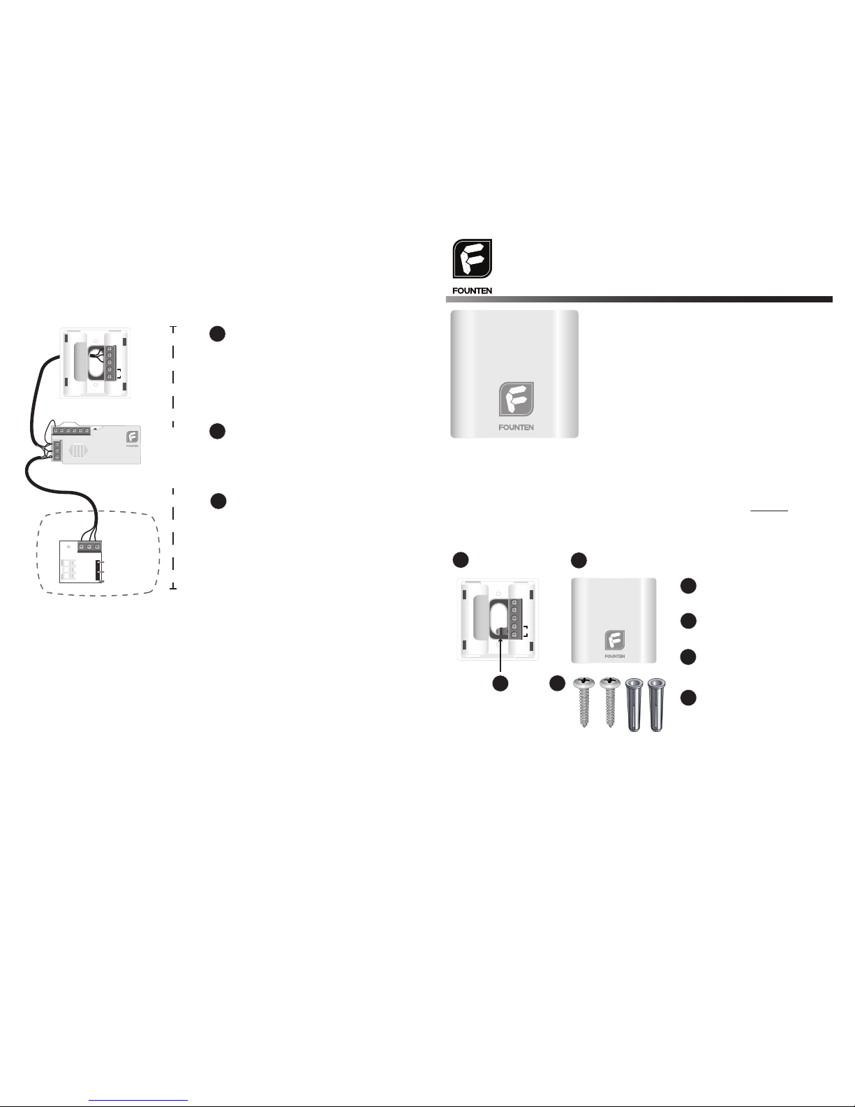
Wall Mounted Back Plate
Front Cover
Internal Temperature
Sensor
D
D
Mounting Hardware
Hardware Provided
Wall Mounting
1
1
2
Remove Wiring Module from the
FS-STAT-32AC(H) thermostat. Install
Wiring Module inside of the air handler.
Refer to page 4 of a FS-STAT-32AC(H)
Installation Guide.
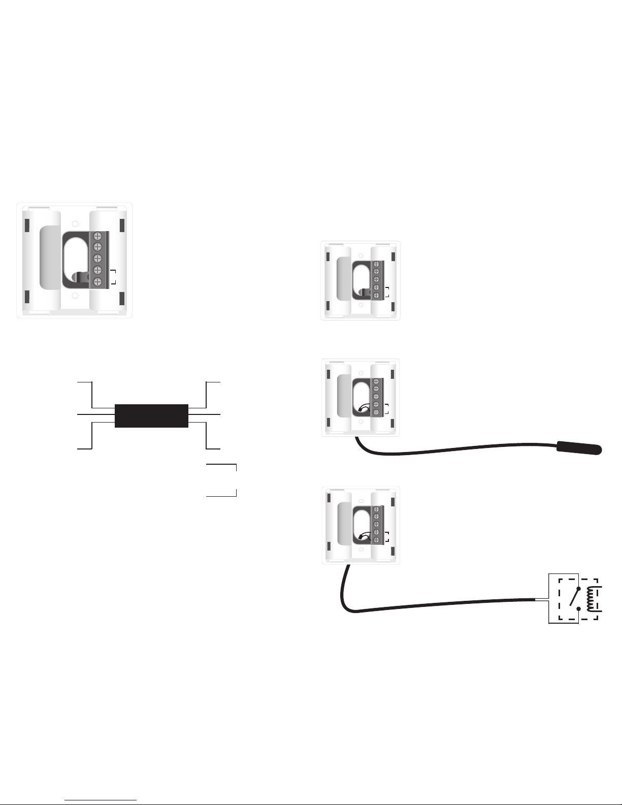
Some installations may have limited in-wall wiring. Use this configuration if no Data Wire or
Common Wire is available. A common application would be to monitor supply air temperature
with limited wires.
Login to your Founten Site Manager Web Application. Select Admin > Thermostat Setup for
the thermostat which has the newly attached FS-TA1. Scroll down until you see a category
labeled “Wired Sensor”
Select the correct Function for your FS-TA1 sensor:
– “Temperature” to use the FS-TA1 sensor instead of the thermostat’s internal temperature
sensor or to allow averaging between the FS-TA1 sensor’s temperature sensor and the
thermostat’s temperature sensor.
– “Alarm” to use the FS-TA1 sensor as an interface for a Dry Contact alarm input. Select
whether a notification should be sent when the contact is opened or closed.
– “Temp Monitor” use the FS-TA1 sensor as a stand alone temperature monitoring device.
(ie. supply air temperature or outside air temperature monitoring).
For additional assistance visit www.Founten.com to request support.
Connect the R, C, and D terminals from the
Wiring Module to matching terminals on the
FS-STAT-32AC(H).
Connect the R, C, D terminals from the
Wiring Module to the matching terminals on
the FS-TA1 sensor.
Note: The sensor can then be used for any one of
the three examples shown on page 3.
Alternate Limited Wiring Option
Wiring Module
FS-STAT-32AC(H) Thermostat
FS-TA1 Sensor
Configuration
3
Up to 500'
max distance
between devices.
4
Rc
R
C
D
Y W G W Y2 2
D C RD C R
T
D
C
R
Wiring Module
Model: FS-WM500
Power: 24-30 VAC
Founten.com
The FS-TA1 sensor requires 3-wires for power and communication with a
FS-STAT-32AC(H); as shown in the diagram above. In many situations you will be able to
simply mount the FS-TA1 sensor on a wall and use the provided 10K internal temperature
sensor to detect the temperature at the desired location.
Follow the guide on page 3 for alternate installation options for the FS-TA1 sensor. The
FS-TA1 sensor can be installed at a maximum distance of 500'from a FS-STAT-32AC(H).
A 10K external temperature probe can be connected to the FS-TA1 sensor up to 100' away.
We recommend using a Founten certified external temperature probe. Contact your local
Founten distributor for assistance.
Note:
2
Wiring Diagram
Thermostat FS-TA1 Sensor
R
10K Temperature Sensor
*Range -20˚F to 180˚F
(-28˚C to 82˚C)
C
D
R
C
D
T
Terminal Designations
T
D
C
R
R − 24 VAC Power
C − Common 24 VAC
D − Data Line
T − 10K Temperature Sensor
For installations where 3-wires already exist or can be run from
a FS-STAT-32AC(H) thermostat to the FS-TA1 sensor. Mount
the FS-TA1 sensor directly on the wall. Connect FS-TA1
sensor’s D, C, and R terminals to matching terminals at
FS-STAT-32AC(H). 500' maximum distance.
Applications:
– Detect temperature inside of an enclosed refrigerator or
freezer.
– Install the FS-TA1 sensor in the conditioned area with the
thermostat placed in a secure, non-visible location.
Remove the internal temperature sensor from the “T” terminal
of the FS-TA1 sensor. Connect the external temperature
probe to the FS-TA1 sensor’s “T” terminal. 100' maximum
distance.
Connect the FS-TA1 sensor’s D, C, and R terminals to
matching terminals of the FS-STAT-32AC(H).
The following wiring options should be used to determine the proper wiring approach for
your application. This guide shows the most common configurations. Contact Founten for
assistance with configurations not shown on this guide.
3
Up to 100'
Up to 150'
T
D
C
R
Wiring Options:
T
D
C
R
Internal Temperature Sensor
2-Wire External Temperature Probe
Interface a Dry Contact Sensor’s output to the input of the
FS-TA1 Sensor in order to create an alarm notification through
your Founten Site Manager.
Remove the provided internal temperature sensor from the “T”
terminal of the FS-TA1 sensor. Connect the output of the
external sensor to the FS-TA1 sensor’s “T” terminal.
Connect the FS-TA1 sensor’s D, C, and R terminals to the
matching terminals of the FS-STAT-32AC(H).
Note: Can be used with normally open or
normally closed contacts.
T
D
C
R
Interface Dry Contact Relay for Alarm Notication
23-26VAC

Popular Accessories manuals by other brands

Timeguard Powerseal TPS204 instructions

Timeguard

Timeguard Powerseal TPS204 instructions

Alarmcom Flex IO installation guide

Alarmcom

Alarmcom Flex IO installation guide

V-tech SN7021 user manual

V-tech

V-tech SN7021 user manual

Silvercrest SAD 12 C2 operating instructions

Silvercrest

Silvercrest SAD 12 C2 operating instructions

AOK HELIOS AC302-02 BI quick start guide

AOK

AOK HELIOS AC302-02 BI quick start guide

Profi Care PC-LK 3088 instruction manual

Profi Care

Profi Care PC-LK 3088 instruction manual

Pro-tec Algo-tec 6000HT Installation, commissioning and service instructions

Pro-tec

Pro-tec Algo-tec 6000HT Installation, commissioning and service instructions

Heath Zenith SL-6200 manual

Heath Zenith

Heath Zenith SL-6200 manual

Uni-Com 66392 operating instructions

Uni-Com

Uni-Com 66392 operating instructions

IB Connect INTRO 2.0 user manual

IB Connect

IB Connect INTRO 2.0 user manual

Rocket Fish RF-LAPCOL Guía del usuario

Rocket Fish

Rocket Fish RF-LAPCOL Guía del usuario

FLORABEST 360594 2007 Assembly, operating and safety instructions

FLORABEST

FLORABEST 360594 2007 Assembly, operating and safety instructions

Aqua Medic Titan 150 Operation manual

Aqua Medic

Aqua Medic Titan 150 Operation manual

iChime The Play Anything Doorbell instruction manual

iChime

iChime The Play Anything Doorbell instruction manual

New Air NBC096BS00 owner's manual

New Air

New Air NBC096BS00 owner's manual

MD SPORTS SOC054_017E Assembly instructions

MD SPORTS

MD SPORTS SOC054_017E Assembly instructions

Oki B4350 Series manual

Oki

Oki B4350 Series manual

Abus GB3010 W installation guide

Abus

Abus GB3010 W installation guide

manuals.online logo
manuals.online logoBrands
  • About & Mission
  • Contact us
  • Privacy Policy
  • Terms and Conditions

Copyright 2025 Manuals.Online. All Rights Reserved.