Four Audio HD2 User manual

Manual for HD2 and HD2Control
Version 1075.4.2
11.12.2009

Contents
1 HD2 In- and Outputs.....................................................................................................................3
1.1 Analog Inputs........................................................................................................................3
1.2 Analog Outputs.....................................................................................................................3
1.3 Digital Inputs and Outputs....................................................................................................4
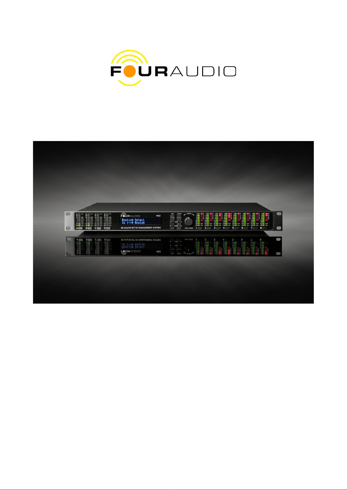
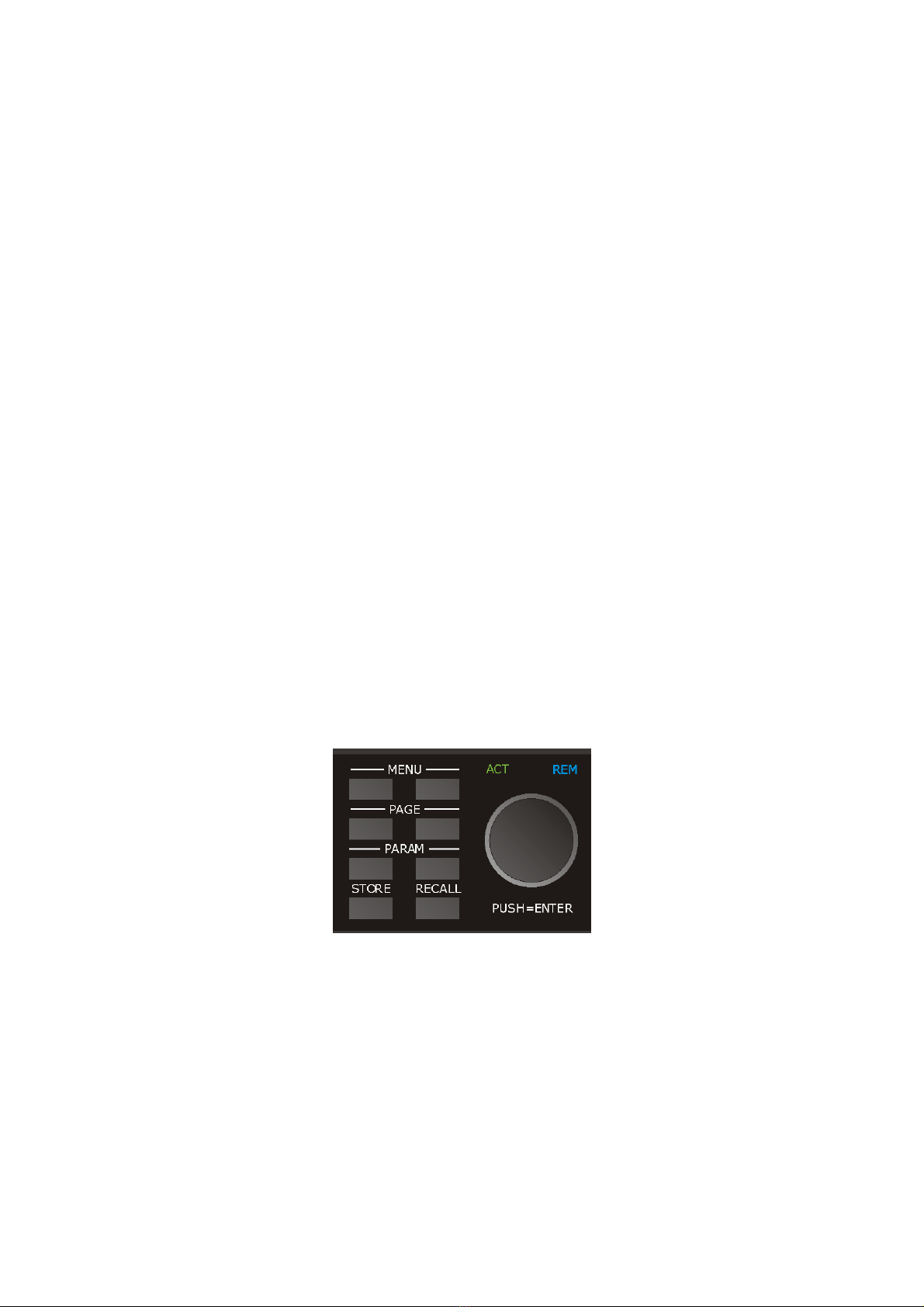
2 Front panel....................................................................................................................................5
3 Basic Usage...................................................................................................................................8
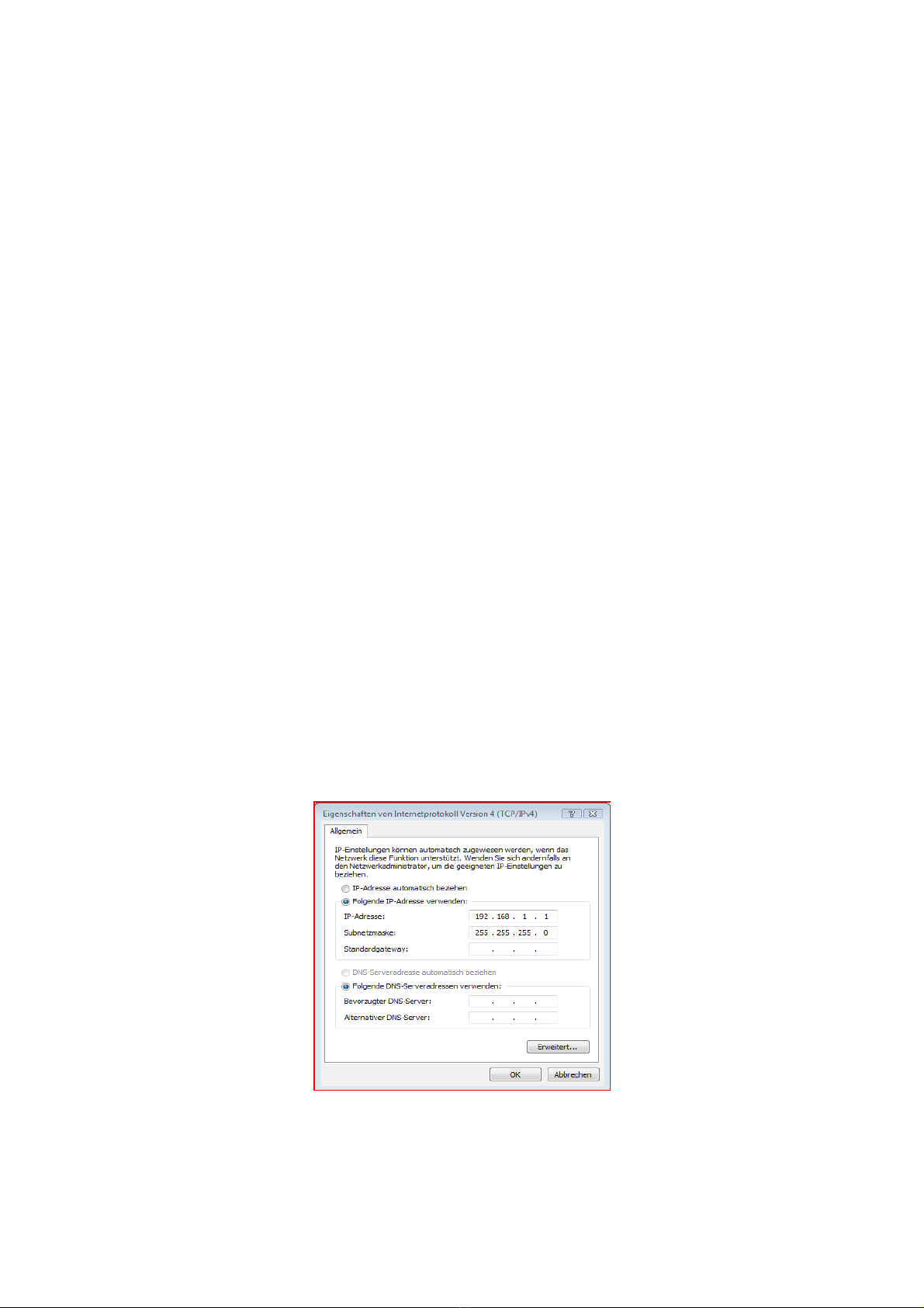
3.1 etwork Setup.......................................................................................................................8
3.1.1 Resetting To The Default IP Address (192.168.1.15)....................................................9
3.1.2 Setting A Specified IP Address......................................................................................9
3.1.3 etwork troubleshooting...............................................................................................9
4 The remote software HD2Control..............................................................................................10
4.1 Installation...........................................................................................................................10
4.2 Starting the Software...........................................................................................................10
4.3 Establishing a connection to the HD2.................................................................................10
4.4 Basic Concept of Operation................................................................................................12
4.4.1 Status Bar....................................................................................................................12
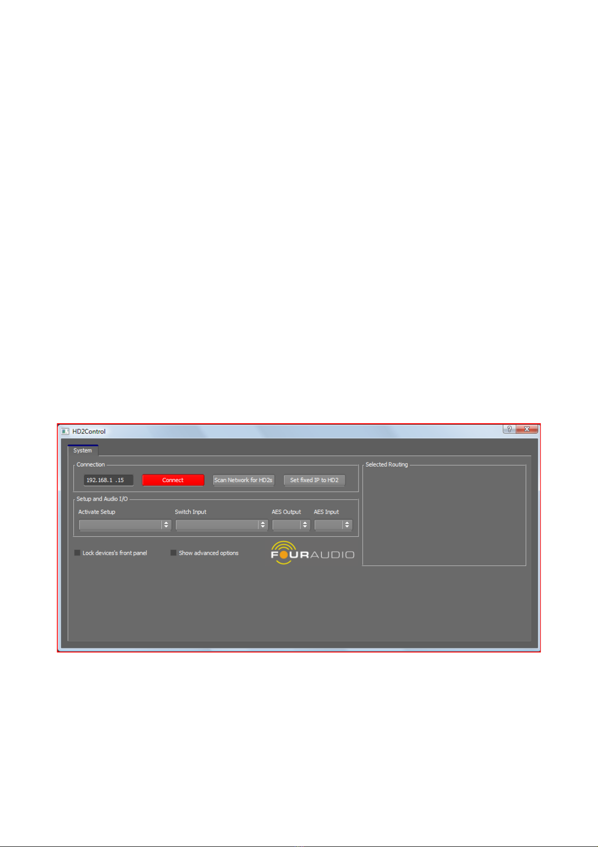
4.5 System Tab (simple mode)..................................................................................................13
4.5.1 Selecting (Recalling) a Setup......................................................................................13
4.5.2 Select Different Input..................................................................................................13
4.6 Advanced Tab .....................................................................................................................13
4.6.1 FIR Filters....................................................................................................................13
4.6.2 Setups..........................................................................................................................14
4.6.3 Configuration Wizard..................................................................................................15
4.6.4 Firmware Update.........................................................................................................18
4.6.5 Erase Flash Mem / Reset to Factory Defaults.............................................................19
4.6.6 Download / Upload the Complete Configuration........................................................19
4.6.7 Locking/disabling the front panel operation...............................................................19
4.6.8 Change the 4 digit security PI ..................................................................................19
4.7 In-/Outputs Tab...................................................................................................................20
4.8 Limiter Tab..........................................................................................................................22
4.9 Input and Output Tabs.........................................................................................................23
2

1 HD2 In- and Outputs
The full-blown HD2 provides several in- and outputs:
1. 2 dual range analog inputs (XLR) or optionally 4 single range inputs (XLR)
2. 8 analog outputs (XLR)
3. 2 digital inputs (selectable: balanced XLR or opto)
4. 2 digital outputs (balanced XLR and opto)
5. 1 Ethernet jack
6. 1 RS 232 connector
In detail
1.1 Analog Inputs
The HD2 provides 2 stereoAD converters with a maximum input voltage of 28.5 dBu.
They can be operated in stacked/dual range or unstacked/single range mode. In stacked/dual range
mode, the left and right channel of one AD converter are combined to form a dual range converter with
a higher dynamic range. The first versions of HD2 usually are set to stacked mode. In later versions,
the AD converter operation mode can be set by software.
Input jack
(label) Function
(stacked/dual range) Function
(single range)
A ADC 0 stacked ADC 0 left
B --- ADC 0 right
C ADC 1 stacked ADC 1 left
D --- ADC 1 right
Early versions:
Early versions have 4 input XLR jacks labelled 1/3, 2/4, 5 and 6. In the housing near the input jacks,
switches are provided to select between inputs 1 and 3 between inputs 2 and 4. In case, a 3rd AD
converter is provided, its inputs are statically connected to inputs labelled 5 and 6.
Input jack
(label) Function
(stacked/dual range) Function
(single range)
1/3 ADC 0 stacked ADC 0 or 1 left
2/4 ADC 1 stacked ADC 0 or 1 right
5 ADC 2 left ADC 2 left
6 ADC2 right ADC 2 right
1.2 Analog Outputs
The 8 analog outputs provide a dynamic range of 121 dB with a maximum output voltage of 18 dBu.
Their use is rather straight-forward. No extra configuration is necessary and no dependence on the
ADC configuration exists. The following table is valid for 2x1->4 routing with the left channel input
connected to Input A and the right channel input connected to Input C.
3

Output jack Function
1 Sub left
2 Low left
3 Mid left
4 High left
5 Sub right
6 Low right
7 Mid left
8 High righ
1.3 Digital Inputs and Outputs
As digital in- and outputs, a balanced AES/EBU in-/output as well as an optical in-/output are provided.
These can be selected in the routing options of the remote software.
Only one 2-channel input at a time can be used, that is, either opto or XLR. The 2-channel output is
always available at the opto and XLR jacks.
4

2 Front panel
On the front panel, LED bargraphs for input and output level as well as LEDs signalling several states
can be found. Below each bargraph, switches for selecting / muting the channel are provided.
Besides the output level meters, a gain reduction meter is provided for each of the 8 outputs. The red
LEDs provide information about the gain reduction induced by the peak limiter. That is, if the level
exceeds 0 dB, the peak limiter limits the signal to not exceed the allowed threshold.
Additionally, an RMS limiter, based on a thermal model of the speakers' voice coil reduces the gain
when the (modelled) temperature exceeds a threshold. The activity of the RMS or temperature limiter is
signalled by the letters TEM glowing red beneath the gain reduction LEDs.
With the buttons beneath the output LED bargraph labelled 1 to 8, the single channels can be muted.A
muted channel is signalled by the letters OFF glowing red.
The SEL LED flashes when the user enters the mode to set gain or delay for one of the input or output
channels. The LED display, then, shows the gain / delay for the channel with SEL flashing. The button
below each channel, then, operates as a select button instead of a mute button.
The input display section consists of 4 level meters and several status LEDs.
CLP: input signal clips
DRC: if lit, input operates in dual range (stacked) mode
ANA: analog input is active on this channel
DIG: digital input is active on this channel
LCK: digital input successfully locked onto the signal
SRC: sample rate converter is used
OFF: input has been muted by the user.
The HD2 can be configured via 8 buttons and a knob which provides an „Enter“ function when pushed
(see Fig. 1)
The front panel operations are not yet fully completed. Thus, the buttons MENU and PARAM are non-
functional. With STORE and RECALL, menus can be entered which allow to store and recall setups
from a list. The PAGE keys navigate through the adjustable settings.After starting up, the HD2 is in the
Master Gain menu. From here, operation of PAGE brings up the menus as shown in the following→
picture:
5
Fig. 1: Buttons for front panel
operation

Parameters can be adjusted by turning the knob. Pushing the knob changes the step size between fine
and coarse. To store or recall setups, enter the menu by pushing RECALL or STORE, select the setup
and push enter.
With the help of the following figure of the internal processing in one of the two DSPs, the adjustable
parameters shall be explained briefly.
Master Gain
Function: Overall gain applied to every path.
Position: Behind the FIR filter block and PEQ bank.
Range: From -88.5 to 39.0 dB
Comments: The default maximum voltage for theAD converters is 28.5 dBu (26.6 Vpp) while the DAC
output voltage range is 18 dBu (7.94 Vpp). Thus, there is a “loss” of 10.5 dB inside the HD2. To obtain a
neutral behaviour with 0 dB gain, the master gain has to be set to 10.5 dB.
Note: From Firmware 1073 upwards, the master gain behaviour has changed. The range depends on
the selected configuration. For analog inputs, master gain ranges from -108.0 to +19.5 dB. A gain of 0
dB, then, provides neutral behaviour.
Master Delay
Function: Overall delay applied to every input
Position: After the PEQ-Bank in the input path
Range: Minimum: 0. Maximum depends on the delay used in the FIR filter and the outputs.
Comments: The delay uses a variant memory pool inside the DSP. That is, if e.g. a high master delay is
used, the maximum channel delay decreases and vice versa.
Input Gain
Function: Input specific gain. Influences input and all connected outputs
Position: After the PEQ-Bank in the input path
Range: -18 to +6 dB
Comments: In this menu, the input to be adjusted is shown on the display and indicated by a lit SEL
6

LED at the corresponding input indicators. To change the input, push the button below the indicator.
Input Delay
Function: Input specific delay. Influences input and all connected outputs
Position: After the PEQ-Bank in the input path
Range: Minimum: 0. Maximum depends on the delay used in the FIR filter and the outputs.
Comments: In this menu, the input to be adjusted is shown on the display and indicated by a lit SEL
LED at the corresponding input indicators. To change the input, push the button below the indicator.
Channel Gain
Function: Output specific gain
Position: After the PEQ-Bank in the output path
Range: -12 to +6 dB
Comments: In this menu, the output to be adjusted is shown on the display and indicated by a lit SEL
LED at the corresponding output indicators. To change the output, push the button below the indicator.
Channel Delay
Function: Overall delay applied to every input
Position: After the PEQ-Bank in the input path
Range: Minimum: 0. Maximum depends on the delay used in the FIR filter and the outputs.
Comments: The delay uses a variant memory pool inside the DSP. That is, if e.g. a high master delay is
used, the maximum channel delay decreases and vice versa.
In this menu, the input to be adjusted is shown on the display and indicated by a lit SEL LED at the
corresponding input indicators. To change the input, push the button below the indicator.
Reset IP
Pushing the knob in this menu resets the IP to the default value 192.168.1.15. After restarting the HD2,
it uses this IP.
Comments: If the HD2 is connected to a DHCP router, this setting has no effect, since the IP assigned
by the router is used.
Additionally, a LED labelled ACT shows network activity in general, while REM signals network activity
for this very HD2.
Earlier versions:
Earlier versions differ from the description as follows:
1. OFF is called MUT
2. the levels are given relative to full scale.
3. DRC LED is not provided
7

3 Basic Usage
The HD2 needs to be connected to its audio sources and sinks, of course. It works with different
programs for its DSPs according to the loudspeaker configuration (number of ways, mode of
equalization, downsampling rates, etc.) and with different FIR filters (if FIR equalization is selected).
The setups and filters can be uploaded from the PC or downloaded to the PC and stored on disk. The
DSP programs are uploaded automatically. The user can just forget about them.
A total number of up to 30 setups can be uploaded simultaneously. The maximum number of FIR filters
is limited to 50 by the program structure but may be lower in reality due to the internal memory size.
The setups contain the total state of the HD2, that is, the routing setup, selected programs and filters,
EQ settings etc.Also the FIR filters are stored in the setup. You can download the setup to the hard disk
and transfer it to another HD2. Since all necessary information is inside the setup, the user just has to
recall the setup in the second HD2 which will behave just like the source HD2.
3.1 Networ Setup
To configure the HD2 externally via a remote PC, it contains a network chip with an own MAC address
which is unique for the HD2. Thus, the HD2 has to be integrated in a network via its Ethernet connector
which can happen in two different ways:
1. If the network is managed by a DHCP server, the HD2 will automatically obtain an own IP.
2. If only static IP addresses without any DHCP server are used, you have to establish a
connection between the remote PC and the HD2 either directly via an Ethernet patch cable or
by using a switch. Connect the HD2s and the PC to the switch. The HD2s then must have
different IP addresses which share the subnet with the PC's IP address.
The HD2 communicates with the remote PC via an own TCP/IP protocol. This requires the appropriate
network setup on the PC.
In case that a DHCP server is used in the network and the PC is already connected to the network, no
further actions are required.
If direct communication between PC and HD2 is desired, the both PC and HD2 have to be in the same
subnet. The default IP address of the HD2 is 192.168.1.15. Thus, open the network configuration on
your PC and modify the properties of the TCP/IP protocol such that the PC has an IP address in the
same subnet, e.g. 192.168.1.1.
If you are using more than one HD2s at a time, you have to assign different IP addresses. This is
8
Fig. 2: TCP/IP configuration

described in section 3.1.1 and 3.1.2 below.
3.1.1 Resetting To The Default I Address (192.168.1.15)
Power on the HD2 and wait until the HD2 has finished booting. Then, use the Page keys on the front
panel and enter the Menu 'Reset IP'. Push the knob. You get a message 'IP reset to 192.168.1.15).
Restart the HD2.
3.1.2 Setting A Specified I Address
Start the HD2Control software (described below). Connect to the HD2 (at 192.168.1.15). When
connected, enter the desired IP address in the IP address field on the top left and click Set IP.
Restart the HD2.
3.1.3 Network troubleshooting
In case that network operation is not working, this checklist may be helpful:
Assuming that the HD2 has an IP address of 192.168.1.15:
–Try to access the HD2 by opening a console, typing 'ping 192.168.1.15' and see, if it reacts.
–The console can be found under Start Programs Accessories.→ →
If you get no response:
Did you use the right cable?
–crossover cable if directly connected to PC
–standard patch cable if connected to router/switch/hub.
Firewall active?
–configure it to not block port 5000
Windows network settings OK?
–TCP/IP protocol installed?
–This is true, if internet access works
If direct connection is selected:
–try to access a second PC
–connect to a second PC via crossover ethernet cable
–look up the IP address of the second PC by typing 'ipconfig' in console on that PC (look for IPv4
address)
–Enter 'ping <ip address of second PC>
–If that succeeds, TCP/IP works in principle.
If the above advices aren't successful, ask an experienced network administrator with nerves of steel.
9

4 The remote software HD2Control
The remote control software HD2Control consists of an executable file called „HD2Control.exe“, a DLL
which encapsulates the communication layer called „HD2Comm.DLL“, several helper DLLs and binary
data files. All of these must be in the same directory.
4.1 Installation
The software package comes in a zipped file containing the following files
HD2Control.exe The executable file
HD2_1075.4.fwu HD2 firmware to be flashed into HD2
To install the software, extract the zip file contents into a directory of your own choice.
The directory which HD2Control.exe resides in must have write access for the current user.A
HD2_Config directory will be created to store temporary data.
4.2 Starting the Software
The software is started by executing HD2Control.exe.
You'll see the following GUI
4.3 Establishing a connection to the HD2
To identify the HD2 in the network, its IP address has to be known. In case of a direct connection, the
default address should be 192.168.1.15 which is the default value in the IP address GUI element in the
upper left corner. If the IP address is obtained from a DHCP server, the HD2 has to be searched for in
10
Fig. 3: HD2Control software after startup

the network.
During the initialization of the software, a splash-screen is shown and the network is scanned for HD2s
connected to it. If only one HD2 is found, it's IP address is shown in the IP edit element labelled IP
Address.A connection can now be established by clicking the Connect button.
If several HD2 devices are connected to the network at the same time, the one used in the last session
is entered into the IPAddress field. To change this, the user has to select the HD2 to connect to. Click
on the Scan Network for HD2s button. After a short time the following dialog will appear
At this time, the network has already been scanned and the found devices are listed in the drop-down
list. The entries consist of the serial number of the HD2 followed by its IP address in the network. In
case, the desired device has not been found, you can retrigger a network scan by clicking Network
scan.
Now select the desired device to connect to and click Select HD2. The dialog will close, the selected IP
address will be transferred in the IP edit field in the main window and a connection will be established.
If the connection is successful, the Connect button changes its label to Disconnect and its colour to
green. The configuration of the HD2 is synchronized with the temporary files on disk and appropriate
tabs are added for operating the HD2.
You'll notice messages appearing in the System Information window.
After this procedure has finished, you'll e.g. see the following main window
11
Fig. 4: etwork Scan Dialog

4.4 Basic Concept of Operation
The software GUI is organized in several tabs. Each of these tabs is explained in detail below. A short
overview follows here:
Tab Functions
System IP settings
Routing
Setup and filter management
Storing and restoring the configuration to the hard disk.
Restore factory settings
Firmware update
In-/Outputs Gain and delay settings for in- and output channels
Level, gain reduction and coil temperature meters
Channel mute and phase inversion
Limiter Limiter configuration
In/Output Tabs EQs (Peak, Shelving, Low-/Highpass) for in and output channels
Filter (Butterworth/Linkwitz-Riley, etc. filters with slopes up to 60dB/oct.)
Frequency/phase response plot of in-/output
4.4.1 Status Bar
Since software version 1075.4.1, a status bar appears at the bottom of the window. At the bottom right,
a handle to change the size appears next to three numbers which display the processing power used
by e.q. Eqs for each DSP and the sampling rate.
12
Fig. 5: HD2Control GUI after connection

4.5 System Tab (simple mode)
In the system tab, you can manage the basic configuration of the HD2. After connecting to the HD2, the
tab is shown in simple operation mode. It allows to change the setup and select different inputs.
4.5.1 Selecting (Recalling) a Setup
The drop-down list labelled Setup Select contains a list of all setups present in the HD2. To recall a
setup, click on the setup list. The drop-down list will open and you can click on the desired entry which
will recall the setup. To cancel, simply press Esc or click on an area somewhere outside the list. Before
switching to the desired setup, a confirmation dialog pops up.
Note: the master gain stored in the setup will not be restored by recalling it. That is, if your master gain
is at -10 dB when recalling the setup, it will not be changed afterwards. If you shut off the HD2 and start
again, it will come up with the gain value it had before shutting off.
4.5.2 Select Different Input
Based on the currently selected routing, different inputs can be selected. In most cases, three input
options are available, namelyAnalog (DRC), Digital (SRC), and Digital (AES). There are, however,
routing presets which do not allow all of these (e.g. routings which use 4 analog inputs). With the drop-
down box, the user can quickly select the desired inputs.
4.6 Advanced Tab
If you check the Show advanced options checkbox in the System menu, an additional tab called
Advanced appears in the task bar.
4.6.1 FIR Filters
FIR filters contain filter coefficients for a maximum of 4 ways. Also, the limiter coefficients are stored in
the FIR filter. The two DSPs in the HD2 provide 4 outputs each. DSP1 provides outputs 1-4, DSP
outputs 5-8. Different FIR filters can be activated for each DSP. By linking the FIR filter settings, the
filter for DSP1 is automatically selected for DSP2.
13
Fig. 6: Advanced options tab

With the controls in the FIR Filter groupbox, FIR filters can be downloaded, uploaded and activated.
After establishing the connection, the drop-down lists are filled with the filters present in the HD2. At the
time of writing, the filters can only be generated with the software Monkey Forest. It generates two
binary files named <filtername>.blk and <filtername>.fcs. The .fcs file contains information about the
filter to be displayed in the GUI. As soon as a filter is uploaded to the HD2, it is newly formatted to
reside in only 1 file with the suffix .fir. You can either upload the .blk file (if the corresponding .fcs file
exists in the same directory) or upload a .fir file. The maximum number of FIR filters in the HD2 is
limited to 30. It may be limited to a lower number by the flash memory size in the HD2.
Activating a FIR Filter
Clicking on a drop-down list will open the list. Clicking on a list entry will activate the filter. It will take
some time until the filter is activated since the coefficients have to be loaded from the flash memory of
the HD2 to the DSP. During switching, the DSP outputs are muted. If the Link to DSP1 switch is active,
the drop-down list for DSP2 is disabled and the selected filter is automatically set on both DSPs.
Activating the switch transfers the filter which is set in DSP1 to DSP2 automatically.
Uploading a FIR Filter
Clicking the Upload to HD2 button opens a file select dialog. Navigate to the desired directory and
select the filter to be uploaded. As mentioned above, you can select a .blk file if the corresponding .fcs
resides in the same directory or a .fir file.After uploading the filter, it appears in the drop-down list and
can be activated.
Downloading a FIR Filter
Clicking the Download to PC button in the FIR filter group box opens a small filter selection dialog. After
the desired filter has been selected, a directory selection dialog comes up. The selected filter is, then,
stored as a file with the extension 'fir' in the selected directory. The file name is automatically derived
from the display name.
4.6.2 Setups
A setup contains the complete state information of the HD2.All settings like gains, delays, IIR filter,
mutes, phase inversions, etc. as well as the FIR filter are stored inside a setup file on hard disk. The
extension of setup files is 'hd2'. At the time of writing, a maximum of 30 setups can be stored inside the
flash memory of the HD2. Depending on the number of FIR filters present in the flash memory, the
number of allowed setups may be limited by the flash memory size.
Unlike FIR filters, setups have a fixed position, that is, you can store a setup at a certain location.
When a modification to the HD2 is made after a setup has been recalled, this setup is marked as
modified by an asterisk (*) behind the setup name in the Activate Setup drop-down box. If the user tries
to recall a different setup, a warning pops up that the current setup has been modified and must be
saved to avoid loss of the recently made settings.
Creating a new (default) setup
For making a new setup from scratch, a “blank sheet” has to be restored to work upon. This can be
done by clicking the New (empty) Setup button. The HD2 will, then, be loaded with default parameters
but no setup or filter is stored or changed.After the user has made the desired settings, a setup can be
stored as usual.
Storing / Creating a Setup in the HD2
After all settings are made in the HD2, the current state can be stored. For that, click the Save Setup as
... button which opens a dialog with a drop-down box where you can select the position, the setup shall
be stored to. Enter a desired name and click the Create setup button. After a successful operation, the
14

setup lists are updated. If a non-empty entry is selected, a warning pops up, that the setup stored at
that position is about to be overwritten.
Downloading a Setup
A setup can be downloaded to hard disk for archiving or uploading it to another HD2. Clicking on the
Download to PC button opens a dialog with a drop-down list which allows to select the setup to be
downloaded. After the desired setup has been selected by Select Setup, the directory to store the setup
to can be selected. The filename is derived from the display name and the extension is 'hd2'.
Uploading a Setup
A setup which was stored to the hard disk can be uploaded easily. Clicking the Upload to HD2 button
opens a dialog where you can either enter the name of the setup file directly or click Browse to search
for it in a file selection dialog. Select a position to upload to. Selecting a non empty list entry will
overwrite the setup at that position.
After successful uploading, the setup list in the system tab is refreshed.
4.6.3 Configuration Wizard
In the Advanced tab, you find a button labelled Configuration Wizard. After clicking the button, you can
select the type of crossover filters, a routing, multipath options and the clock. At any step in the wizard,
you can Cancel, make a step Back or proceed to the Next one. The entered data will be sent to the
HD2 only after submitting by clicking Finish on the last page.
After the introduction screen (not shown), the following dialog comes up:
Please select the type of crossover filters. If you want to use IIR filters, then, there's nothing more to do
here. When you select FIR filters, additional controls show up:
15
Fig. 7: X-Over dialog
Fig. 8: X-Over dialog with FIR filters

You have to select 2 FIR filter files (or only 1 and select Use same FIR filter on DSP1 and DSP2). The
sampling rates of the 2 selected filters have to be the same. If the settings are correct, the Next button
is highlighted. After finishing the wizard, the 2 files will be uploaded to the HD2.
After the crossovers have been selected, the Routing page comes up:
A routing can be selected from the drop-down box. The figure will be updated according to the
selection. There are more than 30 routings available. To reduce the number of reasonable routings a
bit, the filters left and right of the drop-down box can be used. Selecting an Input type 'Analog', e.g.
removes all routings which do not use the analog inputs. Selecting the check box 'Dual range ADC'
(DRC) further removes all entries which do not use DRC. Additionally, a filter can be set on the output
routing in the X-Over drop-down box. E.g. selecting '1->4' shows only routings which support 1->4
crossovers.
Note: when FIR filters are selected, routing presets that do not fit to the filter settings are not shown.
After clicking Next1, the following dialog comes up:
1 If you check the check-box below the filters (“None of the routing presets above suits my needs. ...”) and
click the Next button, an expert mode routing configuration dialog comes up, where the input and output
part can be selected independently. Since this is only for advanced users, it is not explained here. Contact
Four Audio for more information.
16
Fig. 9: Routing page in the Config Wizard

In the left drop-down box, the internal clock, the HD2 operates on, can be selected. If you chose to use
FIR filters in the first dialog.
The multipath options allow to combine several output paths internally and feed, e.g. a speaker with a
passive crossover inside. That is, the speaker is internally treated as a 2 or 3-way speaker (limiters,
filters can be set as for a 2 or 3 way system). The signals at the outputs are, then, added up and fed to
a full-range speaker.
Note: FIR filters provide values for clock and multipath. If you selected FIR filters in the X-Over dialog,
the controls automatically show these values and are disabled.
When you click next, the last page appears (not shown here) and with the Finish button, the settings
are transferred to the HD2.
17
Fig. 10: Multipath and clock options in the config wizard

Stereo filters inside a DSP
When using FIR filters, normally, the 4 outputs of one DSP are configured to feed sub, low, mid and
high paths of a speaker. The HD2 allows to use a stereo mode inside one DSP, that is, it can feed mid
and high 2 times or the coefficients for the high path 4 times. On a HD2 with 8 outputs, you can, then,
feed 4 two-way speakers or 8 one-way speakers. To accomplish that, use a FIR filter with coefficients
for mid and high path only (or high path only) and copy these to the other paths of one DSP. The wizard
automatically detects this possibility from the selected filters and shows 2 additional drop-down lists as
shown in the above picture.
If a 4x1->2 routing is selected, 4 two-way speakers can be fed from 4 different inputs.
4.6.4 Firmware Update
Note: after updating the firmware, all data stored in the HD2 is lost. To prevent loss of data, store the
HD2 configuration to hard disk by Save Config and upload it again after updating the firmware by Load
Config.
Note: the current software HD2Control requires at least firmware version 1071 to operate. You can
connect to HD2s with older firmware versions and do firmware updates but should not expect that the
software fully works with that version.
Upgrading the firmware of the HD2 to a newer version can be done via ethernet. You should have a
valid firmware file named „hd2_v####.$.fwu“ were #### denotes the 4 digit main version number and $
the sub-version number. The file size must be 122.144 bytes. To upgrade, simply push the Update
Firmware button in the Configuration group box at the bottom and select the firmware file in the file
selection dialog. The file will be transferred to the HD2 and copied internally. This takes about 45-50
seconds. After that, a reboot of the HD2 will occur and you should see the new version number
appearing in the display of the HD2.
The ethernet connection to the HD2 is getting lost during rebooting. Watch the messages in the log
window and wait until 'Trying to reconnect' occurs. If all goes well, a new connection is established
automatically. If that doesn't work, you have to connect manually by clicking the connect button.
18
Fig. 11: Using a stereo setup inside a DSP

Note: some DHCP routers are configured in a way that the HD2 obtains a new IP address after a
firmware upgrade (and also after restarting). The IP address of the HD2 before the firmware upgrade
may, thus, not be valid anymore. To cope with this, before trying to reconnect, a network scan is
performed again. If only one HD2 is connected to the network, everything is fine. If more than one HD2s
are connected, the user may have to run the network scan again and select the HD2 manually.
4.6.5 Erase Flash Mem / Reset to Factory Defaults
Pushing Erase All resets the HD2 to the factory default settings, that is, the flash memory is cleared,
master gain is set to -40 dB and the internal DSP program (with no downsampling) and a Dirac impulse
FIR filter is used.
4.6.6 Download / Upload the Complete Configuration
It is possible to download the complete configuration of the HD2 (setups, filters) to a directory and e.g.
upload it to another HD2. Push the button Save Config in the Configuration group in the lower left
corner. You will be asked for a directory to save the configuration into. Inside that directory, files named
set#_<setupname>.hd2, and <filtername>.fir are stored. The # in the setup name refers to the position
in the list visible in the GUI.
To upload the complete configuration, click Upload Config which will ask for the directory to upload
from, scan the directory for valid files and upload them. The HD2 does not have to be empty for this
operation. FIR filters different from the ones that are already present in the HD2 are appended. If an
FIR filter already exists in the HD2, it will not be uploaded.
Setups behave differently since they are fixed to a certain position. If a setup file is named
'Set5_<setupname>.hd2' and a setup already exists in the HD2 at position 5, it will be overwritten. To
prevent this, you can either upload the setups manually or rename the setup such that the number
behind 'Set' is changed to the desired position.
4.6.7 Locking/disabling the front panel operation
To provide unauthorized use of the HD2 from the front panel, the keyboard can be locked with a 4-digit
PIN that consists of numbers between 1 and 8. To lock the front panel, simply click the Lock front panel
checkbox below the log window. If someone tries to operate the HD2 from the front panel, the display,
then, shows “Keys locked - Enter Pin”. To unlock from the software, simply click on the checkbox again.
To unlock from the front panel, enter the 4-digit pin with the output keys labelled with 1 – 8. If
successful, the display shows “Keys unlocked”.
4.6.8 Change the 4 digit security IN
By default, the 4-digit PIN is set to 1111. To change this, click on the Change Security PIN button. The
following dialog comes up:
Enter old and desired new PIN. Note: only numbers between 1 and 8 may be used. If valid numbers
were entered, the Change PIN button is enabled. Click on it to transfer the PINs to the HD2. If the
19
Fig. 12: Change Security
PI

current PIN was entered correctly, the PIN is changed to the new one. In the status log, an appropriate
message shows up.
4.7 In-/Outputs Tab
The gain tab contains indicators for input and output levels and gain reductions of the limiter as well as
controls to set input and output gains, delays, mutes and phase inversions. Depending on the routing
and configuration, the gain tab may look different than shown above. E.g. the names and numbers of
the inputs may change. When more than 4 inputs are used, the gain tab is divided in two tabs. One of
them shows only the inputs, the other one shows only output channels.
Indicators
Input level meters show the level in dBFS relative to the maximum input level (default is 28.5 dBu). The
gain is not influenced by the input gain setting since these are placed behind the level meters.
Output level meters show the level in dBFS relative to the maximum output level (18 dBu)
Gain reduction meters (on top of the output level meters) show the gain reduction induced by both
limiters. That is, if the level exceeds the peak limiter threshold by 4 dB, a gain reduction of 4 dB is
shown. If the RMS or thermo limiter is active, the gain reduction of both limiters are added and shown
here.
Speaker temperature is shown in the bar left to the gain reduction meters (blue bar, gets red on top).
This is the percentage of the allowed maximum temperature as modelled by the thermo limiter based
on the values entered in the limiter dialog.
Peak limiter LED (on top of the output level meters) show the activity of the peak limiter. It is activated
when the ouput level exceeds the allowed threshold (0 dB at the meter), except when the thermo limiter
is active. Then, the allowed threshold is reduced by the thermo limiter, that is, the peak limiter may get
active without the output level reaching 0 dB in the meter.
Thermo limiter LED (on top of the temperature meter) shows the activity of the thermo limiter.
Setting Gains
The gains for inputs and outputs can be controlled with the sliders or by directly typing values in the
corresponding edit fields below the sliders.
20
Fig. 13: In-/Output dialog with level, gain reduction and temperature meters
This manual suits for next models
1
Table of contents