Fox F31-462A User manual

1
BELT SANDER 100mm
AND DISC 150mm
(Fox Model F31-462A)
INSTRUCTION MANUAL

2
SUMMARY
INSTRUCTION MANUAL 3-28
EXPLODED VIEW 29-30
WIRING SCHEME 31
DECLARATION OF CONFORMITY 32

3
Belt sander 100mm and disc 150mm (FOX Model F31-462A)
TABLE OF CONTENTS
Safety rules Page 5
General safety rules Page 6
Additional safety requirements for sanders and belt drive Page 8
Environmental protection Page 9
Symbols Page 10
Electrical connections Page 11
Recommendations of use Page 12
Specifications Page 13
Noise information Page 13
Unpacking and cleaning Page 14
Parts identification Page 15
Mounting Page 17
- Mounting the sanding disc and housing Page 18
- Assembling and replacing the sanding belt Page 18
- Assembling the worktable for use with the sanding disc Page 19
- Assembling the worktable for use with the sanding belt Page 19
- Installing the support plate Page 20
- Mounting the sander on a workbench Page 20
- Mounting the sander using clamps Page 20
Settings Page 21
- Centering the sanding belt Page 21
- Angle between the table and sanding disc Page 22
Operation Page 22
- On / off switch Page 22
- Sanding a bevel Page 22

4
- Sanding an end surface with the guide tabs Page 23
- Sanding with the sanding belt - horizontal/vertical Page 23
- Sanding a surface on the sanding belt Page 23
- Sanding a curved piece Page 24
Maintenance Page 25
- General information Page 25
- Changing the drive belt Page 26
Troubleshooting Page 27
Assistance Page 27
DART Tool Group Guarantee Page 28

5
SAFETY RULES
ATTENTION :
While following the instructions in this manual, when you use a power tool, you must still follow all precautions to
prevent the risk of fire, electric shock and injury.
Read this instruction manual before putting the machine into operation and keep it carefully.
Working with power tools can be dangerous if you do not follow proper safety measures. As with any electrical
machine with moving parts, the use of certain hazards involved. If you use the machine as shown in the manual that
you pay attention to the work you are doing, you observe the regulations and use appropriate personal protective
equipment, the potential for injury will be significantly reduced. The remaining potential risks are related to:
1 - electric shock due to direct or indirect contact with electrical parts.
2 - injury from contact with moving parts.
3 - injury from contact with angular or sharp parts, or changing the blade.
4 - injuries due to the ejection of tool parts or the material you are working.
5 - injuries due to noise.
6 - injury due to dust.
7 - injuries due to incorrect installation of the machine.
Safety equipment such as guards, push sticks, restraints, featherboards, safety goggles, dust masks, hearing
protection, safety shoes and gloves can reduce the possibility of injury. But even the best guard will not against a
lack of common sense, care or attention. Always use common sense and take precautions in the workshop. If a
procedure feels dangerous, do not try it. Work out a safer method. REMEMBER: safety is everyone's responsibility.
This tool was designed for specific uses. FOX strongly recommended not to change it and / or used for any
application other than that for which it was designed. If questions arise about a particular application, DO NOT use
the tool until you have contacted FOX to determine if the tool can be used in this way.
READ AND KEEP THIS MANUAL.

6
GENERAL SAFETY RULES
1. Keep the work area clean. Work areas and cluttered benches invite injuries.
2. Avoid a dangerous environment. Do not expose power tools to rain and do not use in damp or wet locations.
Keep the work area well lit. Do not use the tool in presence of flammable gases or liquids.
3. Connect dust extraction equipment. If means are provided for the collection of dust, ensure that these devices are
connected and properly used.
4. Keep visitors and children away. All children and visitors should be kept a safe distance from the work area.
5. Protect yourself from electric shocks. Avoid contact with earthed surfaces.
6. Do not mistreat the power cord. Never pull the power cord to disconnect the plug. Keep the power cord away from
heat, oil and sharp edges.
7. Use extension cords intended for outdoor use. When the tool is used outdoors, use only extension cords intended
for outdoor and bearing indications to this effect.
8. Be aware. Observe what you do, use common sense. Do not use the tool when you are tired.
9. Do not use the machine if you are under the influence of medication, alcohol or drugs.
10. Avoid accidental starting. Make sure the switch is in the “Off” position before plugging in.
11. Dress properly. No loose clothing or jewellery that can be caught in moving parts. Non-slip footwear is
recommended for outdoor work. Keep long hair covered or tied up.
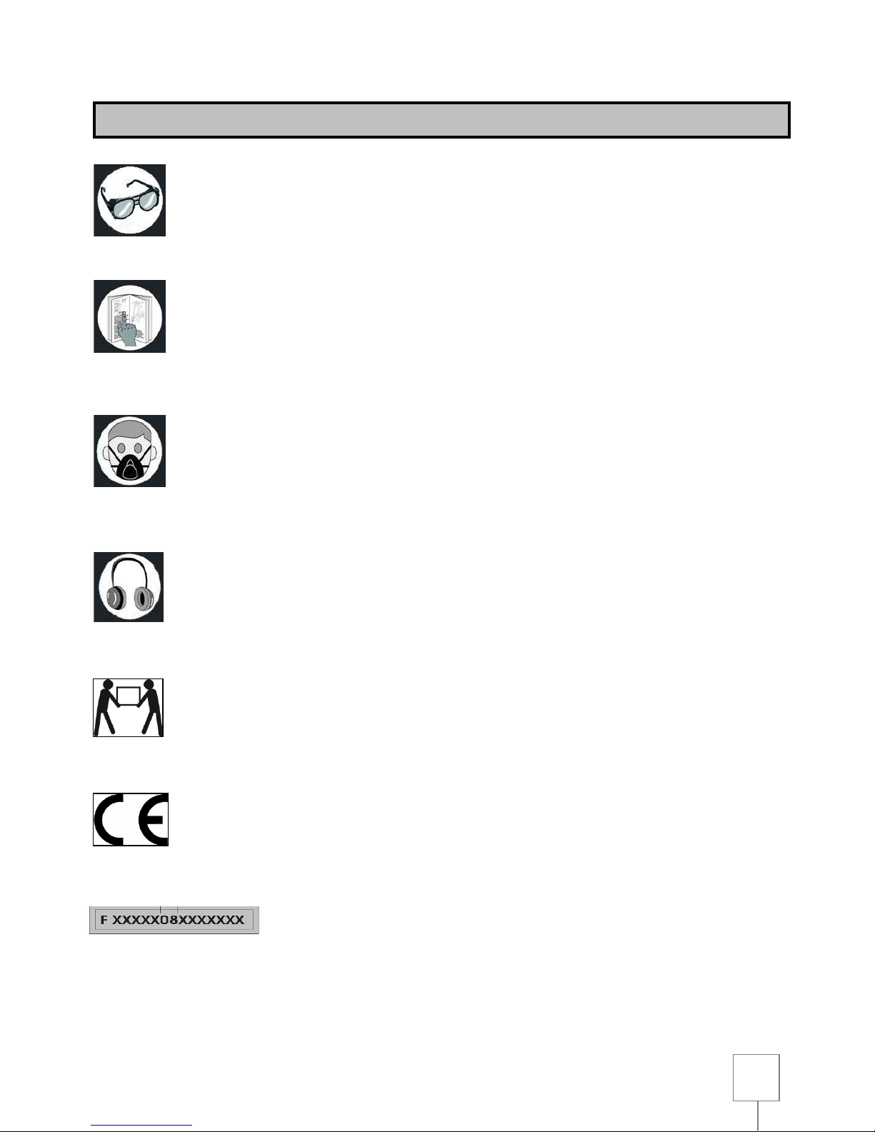
12. Always use personal protection devices: wear safety glasses. Wear a mask if operation is dusty. Wear
hearing protection or earplugs in noisy areas. Wear protective gloves when handling parts with sharp edges.
13. Do not lean over the tool. Keep your balance at all times.
14. Seek the advice of an expert if you are not familiar with the use of this machine.
15. Store tools when not in use. They should be stored in dry, locked storage out of reach of children.
16. Do not force the machine. It will work better and safer when used in the way it was designed.
17. Use the right tool. Do not force a small tool to do the job of a heavy duty tool. For example, do not use a circular
saw to cut branches or logs.
18. Secure what you are working on. Where possible, use clamps or a vice. It's safer than using your hands.
19. Keep tools in good condition. Keep tools sharp and clean in order to get the best and safest performance. Follow
instructions for lubricating and changing accessories. Regularly check the cable and replace if damaged. Keep
handles dry, clean and free of oil and grease.

7
20. Unplug the tool when not in use, before servicing and when changing accessories such as blades, bits, cutters,
etc.
21. Keep keys and adjusting wrenches. Check that all keys and adjusting wrenches have been removed from the
tool before turning it on.
22. Inspect parts for damage. Before continuing to use the tool, inspect any guard or other part that may be
damaged to ensure that it works well and performs the intended task. Check that moving parts are properly aligned,
do not get caught and are not broken. Also, check the assembly for anything else that may affect its operation. Any
damaged part should be properly repaired or replaced by an authorised service centre. Do not use the tool if the
switch does not work properly.
23. Use the machine, tools and accessories in the manner and for the purposes mentioned in this manual.
Different use or use of any accessory not recommended in this manual may present a risk of injury to the user.
24. Have your tool repaired by a qualified person. This power tool is manufactured to relevant safety requirements.
Repairs should only be made by a qualified person using original spare parts, otherwise it may present a danger to
the user.

8
ADDITIONAL SAFETY RULES FOR SANDERS
1. ALWAYS UNPLUG the power sander before making any repairs, changing the belt or disc, cleaning or
maintenance.
2. DO NOT USE the sander before it is completely assembled and installed according to instructions.
3. PROTECT your eyes with safety glasses and use a dust mask
4. NEVER wear gloves or hold the workpiece with a cloth when sanding.
5. AVOID any positions where your hands may slip suddenly and touch the belt or sanding disc.
6. INSTALL and use the sander on flat surfaces only.
7. ENSURE the sander sits securely, if there is a possibility it could move or fall over.
8. MAKE SURE that the sanding belt is running in the right direction with reference to the arrow on the inside of the
band, and that it runs centered so that it does not come out of the pulleys.
9. MAKE SURE the belt and disk are not torn and are positioned correctly.
10. ALWAYS PLACE the piece you are working with on the stop band when sanding on belt or disk.
11. DO NOT SAND if the piece you are working with is not supported. Support the workpiece with the bumper or
table. The only exception is the sanding areas on the outside of the sanding drum.
12. BE SURE to always maintain a maximum of 1.6 mm of space between the table and the stopper and the disc or
the sanding belt.
13. ALWAYS hold the workpiece firmly when sanding.
14. DO NOT SAND pieces that are too small to safely hold.
15. WHEN sanding a large unit, ensure it is supported properly.
16. ALWAYS SAND on the trailing side of the disc when it is used, so that the part is held firmly on the table.
Sanding on the upward side of the disc can make the sander move, which can be dangerous.
17. SAND in the direction of the wood grain.
18. NEVER move or alter the table when the machine is running.
19. CLEAR the table of any rubbish or other objects before installing and using the machine.
20. NEVER LEAVE the work area when the machine is on or before the machine has stopped completely.
21. UNPLUG the machine, clean the work area after use and before a long period of inactivity.
22. REPLACE missing or damaged parts. Do not use the sander unless it is completely assembled and functional.
23. CHECK the power cord regularly damage. If it is damaged, have it repaired by an authorised service centre.
Regularly check the extensions and replace if damaged.

9
ENVIRONMENTAL PROTECTION
INFORMATION TO USERS
Under the terms of art. 13 of Legislative Decree of 25 July 2005, No. 151 "Application of Directives 2002/95 / EC,
2002/96 / EC and 2003/108 / EC relating to the reduction of the use of hazardous substances in electrical and
electronic, as well as waste disposal ", it states the following:
•The symbol of the crossed-out dustbin on the equipment or packaging indicates that the product should be
disposed of separately from other waste at the end of its useful life.
•Therefore, the user must return the equipment to recycling centres which specialise in collection of electronic and
electrical waste, or return it to the retailer when purchasing a new equipment equivalent type.
•The appropriate recycling, treatment and disposal of this item helps to avoid possible negative effects on the
environment and promotes the reuse and / or recycling of materials making up the equipment.
ATTENTION: The illegal disposal of the product by the user may result in the legal
action against the user.

10
SYMBOLS
Always wear protective goggles when using this machine.
Read and understand the instruction manual before using the machine
Always wear a protective mask if the operation is dusty.
Always wear ear defenders when using the machine.
Heavy lift. Transporting the machine requires two people.
Product meets relevant CE standards.
Serial number / year of manufacture.

11
CONNECTING THE SAW
ELECTRICAL CONNECTIONS
ELECTRICAL CONNECTION
Your machine has a precision built electric motor. It must be connected to a power supply of 230V, 50 Hz. If your
machine does not operate when plugged into an outlet, double check the power supply.
EARTHING INSTRUCTIONS
In case of malfunction or short circuit, grounding provides a path of least resistance for electric current to reduce
the risk of electric shock. This tool is equipped with an electric cord having an earthing conductor and a grounding
plug. The plug must be plugged into a matching outlet that is properly installed and grounded in accordance with all
local codes and regulations.
Do not modify the plug provided. If it does not fit into the outlet, have a proper outlet installed by a qualified
electrician. Improper connection of the conductor grounded equipment can result in a risk of electric shock. The
conductor with insulation is green with or without yellow stripes is the conductor of grounding. If the repair or
replacement of the power cord is necessary, do not connect the grounding conductor to a live terminal.
If the earthing instructions are not completely understood, check with a qualified electrician or a person responsible
for maintenance, or if there is doubt properly grounding the tool.
If the power cable is damaged, it must be replaced by the manufacturer, after sales service or similarly qualified
persons in order to avoid a hazard. Do not operate the tool with a damaged power cable.
This tool is intended for use on a circuit with a wall outlet. It also has an earthing pin.

12
EXTENSION CORDS
When using the power tool at some distance from the socket, be sure to use an extension cord powerful enough to
carry the current that the tool needs. An undersized extension cord will cause a voltage drop in the line leading to
overheating and power loss. Use the table to determine the minimum size of son required in an extension cord.
Only extension cords in accordance with the EC standards may be used.
Cord length : up to 15m
Wire size : 3 x 2.5m2
Before using any extension cord, make sure it has no parts are bare and that the insulation is not cut or worn.
Repair or replace immediately a damaged or frayed cord.
ATTENTION :
Extension cords must be removed from the work area or located so that they will not get caught in parts,
tools or other objects while using the tool.
ATTENTION :
KEEP ELECTRICAL TOOLS AND EQUIPMENT AWAY FROM CHILDREN.
RECOMMENDATIONS OF USE
The belt sander and disc was designed and built for all the work of sanding wood and similar materials to wood.
Sanding of other materials may present a risk of fire, accidents or damage.
The sanding strip can measure 914mm long by 100mm wide, while the disc should have a diameter of 152mm.
The belt is tensioned by a tensioning system, while the disc is to be glued to its support. The table can be tilted from
0 to 45 degrees and you can use it to work with the disk or tape, but in this case the belt should be positioned
vertically.

13
SPECIFICATIONS
Motor : 370 W
Voltage and frequency : 230 V –50 Hz
Sanding strip
Width : 100 mm
Length : 914 mm
Speed : 450 m/mm
Length of the table : 360 mm
Tilt : 0° to 90°
Sanding disc
Diameter : 152 mm
Disc speed : 2850 minˉ¹
Table de travail Worktable
Dimensions : 158 x 225 mm
Tilt : 0° to 45°
Overall dimensions : 302 x 545 x 430 mm
Weight : 20 kg
NOISE INFORMATION
The noise level of the machine, measured according to EN 60129, EN 3744 - EN 11201 are:
- Sound pressure level LpA: 76.7 dB (A) void and 82.3 dB (A) with workload
- Sound power level LwA: 88.5 dB (A) void and 91.8 dB (A) with workload
- Margin of error K: 3 dB
It is recommended to use a protection against noise.
The sander emits noise from the electric motor and its ventilation system, cruise control, movement of the sanding

14
belt and disc, as well as the piece you are working against the disc or belt.
It is advisable to check the engine, its ventilation system and air routes. Check the condition of the cruise control, the
tension of the band and the material to be ground. Properly maintain the workpiece.
The quoted values are emission values calculated using standard values and are not representative of use within the
workplace. Although there is a correlation between levels of emission, it is impossible to draw any conclusions about
extra precautions to make. Factors with potential influence on the sound level at the place of work include working
time, the size of the room and other noise sources (eg the number of machines in operation, other noisy operations
performed at the same time). Noise thresholds vary from one country to another. However, these instructions allow
the machine user to better assess the dangers and risks.
UNPACKING AND CLEANING
Your new belt sander and disc comes complete in a box. Unpack it carefully and make sure that
nothing is missing and there are no damaged parts. Do not throw away the box until the
machine has been checked carefully, all parts identified, and you have used the device to
satisfy yourself that it is fully functional.
If parts are damaged or missing, do not plug the sander and do not turn the switch to the "on" position so as not to
compromise the effectiveness and safety of the tool. Contact an authorised service centre for replacement of
defective or missing parts.
To make the sander fully operational, install the parts as described in the following paragraph.
Please read the installation instructions and follow them carefully.
Figure 2 illustrates the sander and all spare parts supplied with the machine.
Remove the protective coating from all parts that are not painted. This protective coating can be removed with a soft
cloth moistened with WD40. Do not use acetone, gasoline or paint thinner.
List of parts supplied:
•Self-adhesive sanding disc
•Disc housing
•Phillips Screws (2)
• Mounting screws M8x12 (2)
•Washers (2)
•Tab Guide
•Hex key
•Work Table
• Backstop

15
PARTS IDENTIFICATION
Suction
outlet

16
TILT INDICATOR
The work table is supplied with a tilt indicator; it allows adjustment of the inclination of the table to 45°.
SANDING BELT TENSION LEVER
This lever allows you to remove the tension on the sanding belt for easy replacement of the sanding belt.
TILTING SANDING BELT
Use a 6mm Allen key to release the band. Loosen the 6mm screw on the plastic protector of the belt (FIG positioning
holes). Adjust the tilt angle of the band. Tighten the screw with the 6mm Allen key.
SANDING BELT
The position of the sanding strip can be adjusted between horizontal and vertical to suit the shape and size of the
piece to be sanded.
Switch

17
SANDING DISC
The sanding disc is located on the side of the tool.
On / Off SWITCH
The sander has an easily accessible power switch.
CENTERING BUTTON
The centering button allows the sanding belt to be centered.
STRIP BACKSTOP
To help keep the piece to be sanded on the sanding belt. The supplied backstop may differ from the illustration.
WORKTABLE
The machine has a rugged work table which provides a stable support surface for the sanding with the disk or
sanding belt.
MOUNTING
WARNING !
Do not start the sander until you have read and understood the manual, or until the machine has been fully
installed.
DANGER !
Turn off and unplug the sander from the power source and wait until the belt and disc are completely
stopped before making any adjustments, changing the belt or any maintenance on the unit.

18
MOUNTING THE SANDING DISC AND HOUSING
Figure 4
Remove the back sheet of the sanding disc.
Align the perimeter of the sanding disk with the support
plate; firmly apply to ensure it sticks.
Place the housing against the lower 1/3 of the disc;
align the holes as shown in Figure 4.
With two Phillips screws, secure the cover in place.
Always remove the worn disc completely before fitting
a new one.
ASSEMBLING AND REPLACING THE SANDING
BELT
Figure 5
Directional arrows within the band to indicate the direction of
rotation of the sanding belt.
Remove the lower cover plate.
Pull the tension lever to remove the tension on the
sanding belt
Loosen the belt support tilt screws to allow tilting
support
Unscrew the two stop fixing screws and remove the
stop
Remove the tape.
Place the new sanding belt and the driving drum and
the free drum; the arrows should be oriented for movement in a
counterclockwise direction.
Make sure that the sanding belt is centered on both
drums.
Push the tension lever to apply tension on the sanding
belt.
Replace the backstop.
Replace the bottom cover plate and secure it with two
screws.
Reposition the band in a horizontal position.
Tighten the mounting screws.
Note: The tensioning lever is tensioned by a spring; be careful
when applying pressure to avoid injury.

19
ASSEMBLING THE WORKTABLE FOR USE WITH THE SANDING DISC
Figure 6
To use the worktable with the sanding disc :
Insert the table mounting rod into the hole as shown in Figure 6.
Position the worktable no more than 1.6mm (1/16 inch) from the sanding surface.
With an Allen key, tighten the table fixing screws on the stem.
Move the table to the desired angle and tighten the table nut.
ASSEMBLING THE WORKTABLE FOR USE WITH THE SANDING BELT
Figure 7
To use the worktable vertically :
•Insert the table mounting rod into the hole as shown in Figure 7.
• Position the worktable no more than 1.6 mm (1/16 inch) from the sanding surface.
•With an Allen key, tighten the table fixing screws on the stem.
•Move the table to the desired angle and tighten the table nut

20
INSTALLING THE SUPPORT PLATE
Figure 8
• Position the workpiece support plate over the holes on
the side of the tool housing, as shown in Figure 8.
•Use an Allen key to tighten the screws (do not forget to
use the washers).
MOUNTING THE SANDER ON A
WORKBENCH
Figure 9
If the sander is not to be portable, attach it to a
workbench or other stable surface.
•Make marks on the bench for the holes that will fix your
sander. Use the holes in the base of your sander as a
template for the layout of the holes.
•Drill holes in the workbench.
• Place the sander on workbench aligning the base holes
with the holes in the workbench.
•Insert the bolts (not included) and tighten them using
brake washers and hex nuts (not included).
Note: All bolts should be inserted from above. Fit the
locking washers and nuts beneath the workbench.
MOUNTING THE SANDER USING CLAMPS
Figure 10
If the sander is to be transported for use at different
locations, we recommend you permanently attach it to a
mounting panel that can be easily attached to a
workbench or other surface using clamps. The mounting
panel must be large enough to prevent tipping of the
sander during use. We recommend using a piece of
good quality plywood or chipboard 19mm (3/4 inch)
thick. See the previous section for how to fix the
machine to the panel.
If using lag bolts, make sure they are long enough to go through the holes in the base of the sander and the material
on which the sander is mounted. If using bolts, make sure they are long enough to pass through the holes in the
base of the sander, the material on which is mounted sander, the lock washers and hex nuts.
Table of contents
Other Fox Sander manuals