FoxESS EPS Box-TP User manual


Table of Contents
1. Introduction ................................................................................................................................................................... 1
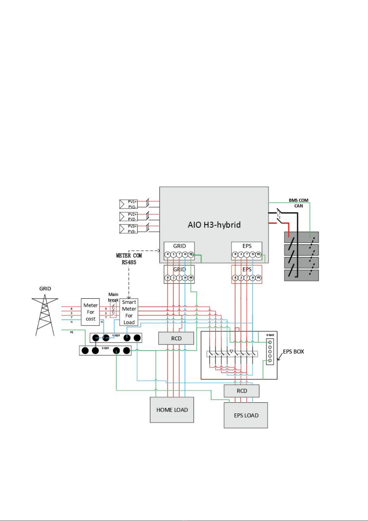
1.1 Wiring Diagram .................................................................................................................................................2
2. Preparation .................................................................................................................................................................... 4
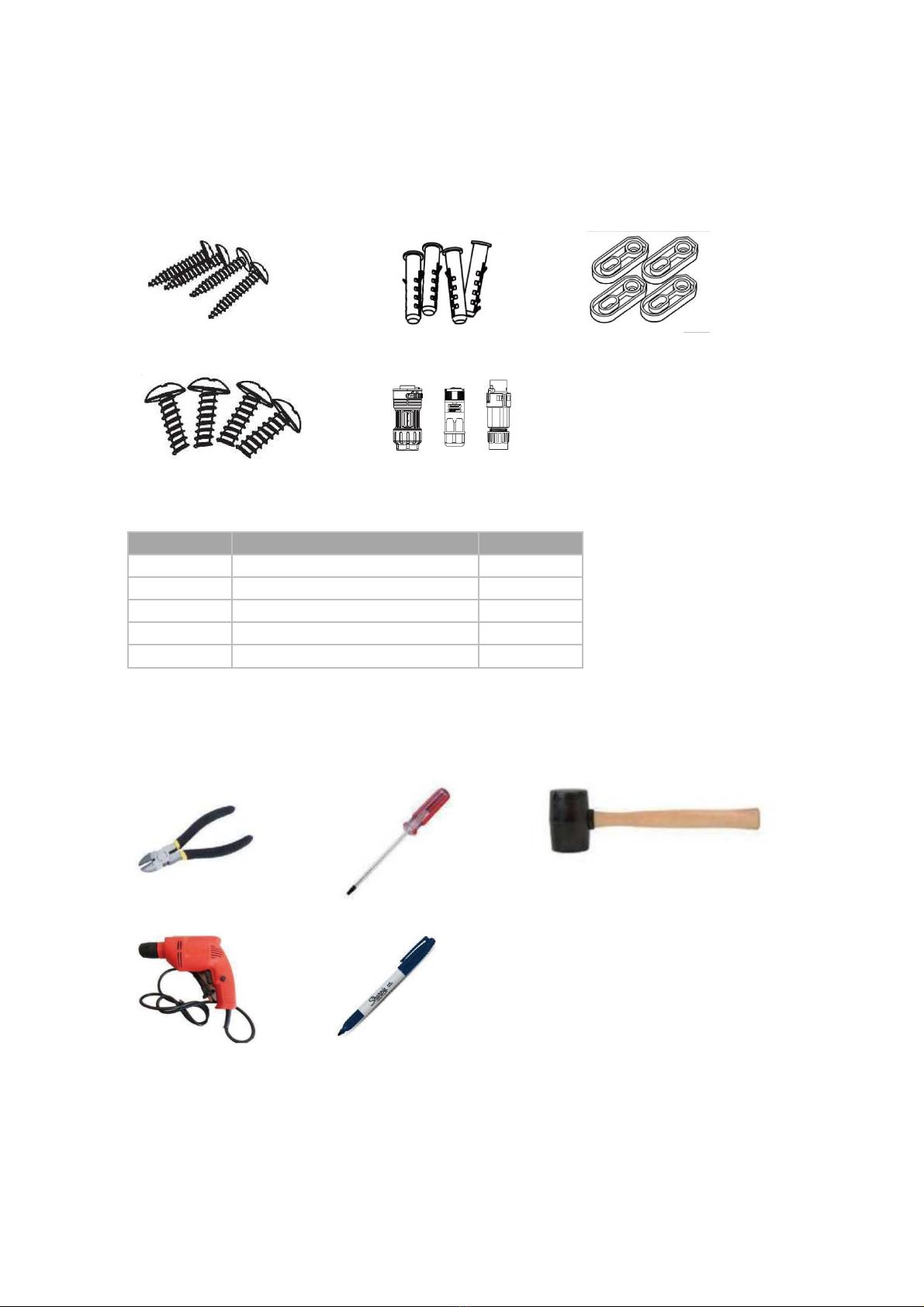
2.1 Package Contents ............................................................................................................................................4
2.2 Tools ...................................................................................................................................................................4
3. Mounting ........................................................................................................................................................................ 5
4. Wiring Connection ........................................................................................................................................................ 6
4.1 Overview of EPS Box-TP ..............................................................................................................................10
5. Technical Parameters ............................................................................................................................................... 11


EPS Box-TP Series User Manual www.fox-ess.com P a g e | 1
1. Introduction
EPS Box-TP integrates two contactors which provides simple connection for users. It is compatible with equipment
with back-up function. Configured with EPS Box, customers just need to connect 3 wires between inverter and EPS
Box. It can simplify the operation and improve security.
Overview :
Objeto
Descripción
1
LOAD
2
EPS
3
ON-GRID

EPS Box-TP Series User Manual www.fox-ess.com P a g e | 2
1.1 Wiring Diagram
Note:the following is the wiring diagram of EPS BOX TP. It is necessary to connect the ON-GRID side of EPS BOX TP to
the power grid, connect the EPS port to the EPS port of the energy storage machine, and connect the LOAD port to the
load at home. The function of TP is to select the power of the load port from the GRID or the EPS port of the energy storage
machine.
Note: According to Australian safety requirements, the neutral cables of the on-grid side and backup side must be
connected together.Otherwise, the backup function will not work.
This diagram is an example for an application that neutral connects with the PE in a distribution box. For countries such as
Australia, New Zealand, South Africa, etc, please follow local wiring regulations.

EPS Box-TP Series User Manual www.fox-ess.com P a g e | 3
This diagram is an example for an application in which neutral is separated from the PE in the distribution box.
For countries such as China, Germany, the Czech Republic, Italy, etc, please follow local wiring regulations.Need internal
or external eps box, connect PE and the off-grid N line.

EPS Box -TP Series User Manual www.fox-ess.com P a g e | 4
2. Preparation
2.1 Package Contents
Before installation, make sure that nothing inside the package is damaged. The following items
should be inside the package.
2.2 Tools
Before you start, get the following tools ready.
Number
Items
Quantity
A
Expansion Screws
4
B
Expansion Tubes
4
C
Cushion Blocks
4
D
Self-Tapping Screws
4
E
AC Connectors
3
Diagonal Plier
Screwdriver
Rubber Hammer
①6 Driller
Marker Pen
A B C
D
E

EPS Box -TP Series User Manual www.fox-ess.com P a g e | 5
3. Mounting
Step 1: Install the four cushion blocks on EPS Box -TP with self-tapping screws.
Step 2: Use EPS Box-TP with cushion blocks as a template to mark the four holes' position on the wall with
marker pen.
Step 3: Drill holes with 力6 driller carefully, make sure the holes are deep enough for installing. Install the
expansion tubes through cushion blocks into the holes and tighten them.

EPS Box -TP Series User Manual www.fox-ess.com P a g e | 6
Step 4: Install the expansion screws with screwdriver to fix the EPS Box-TP.
4. Wiring Connection
Step1: Grid String Connection
EPS Box-TP is designed for three-phase grid. Per voltage range is 220/230/240V; frequency is
50/60Hz. Other technical requests should comply with the requirement of the local public grid.
Model(kw)
5.0
6.0
8.0
10.0
12.0
Cable (Load)
6.0mm2
6.0mm2
6.0mm2
6.0mm2
6.0mm2
Cable (ON-GRID)
4.0mm2
4.0mm2
4.0mm2
4.0mm2
4.0mm2
Cable (EPS)
4.0mm2
4.0mm2
4.0mm2
4.0mm2
4.0mm2
Micro-Breaker
32A
32A
32A
32A
32A
Step 2: Grid Wiring
•Check the grid voltage and compare with the permitted voltage range (refer to technical data).
•Disconnect the circuit-breaker from all the phases and secure against re-connection.
•Trim the wires:
-Trim all the wires to 52.5mm and the PE wire to 55mm.
-Use the crimping pliers to trim 12mm of insulation from all wire ends as below.
L1/L2/L3: Brown/Red/Green or Yellow Wire
N: Blue/Black Wire
PE: Yellow & Green Wire
Note: Please refer to local cable type and color for actual installation

EPS Box-TP Series User Manual www.fox-ess.com P a g e | 7
A. EPS Wiring
Set the parts on the cabl
Crimp wires, screw twisting torque 0.8+/-0.1N m.
Put the sealing body and yarn trapper into the main body, screw the lock nut into the main body, and the
torque is (2.5 + /- 0.5N m).
Insert the male end into the female end. For the rotation direction of the lock, please refer to the LOCK
mark on the assembly.
B. ON-GRID Wiring
Separate the ON-GRID plug into three parts as below.
-Hold middle part of the female insert, rotate the back shell to loosen it, detach it from female inset.
-Remove the cable nut (with rubber insert) from the back shell.

EPS Box-TP Series User Manual www.fox-ess.com P a g e | 8
Slide the cable nut and then Install the back shell onto the cable.
Push the threaded sleeve into the socket, tighten up the cap on the terminal.
Remove the ON-GRID connector: Press the bayonet out of the slot with a small screwdriver or the unlock
tool and pull it out, or unscrew the threaded sleeve, then pull it out.
C.Load Wiring
Wire Stripping
Wire:

EPS Box -TP Series User Manual www.fox-ess.com P a g e | 9
Installation of cable end connector
Step 1:Set the parts on the cable.
Step 2:Wire crimping cord end terminal can be inserted into the housing quickly according to the sign ,
torque 1.0+/- 0.1N·m.
Step 3:The housing is inserted into socket, then the unlock key is inserted into socket.
Step 4:Insert Seal and Clamp Finger into socket ,then tighten the nut , torque 8+/-2N·m.

EPS Box-TP Series User Manual www.fox-ess.com P a g e | 10
Male female connection
Disassembly Connector
Step 1:Unmating the plug and the socket
Step 2:tighten the unlock key,then pull the plug
4.1 Overview of EPS Box-TP

EPS Box -TP Series User Manual www.fox-ess.com P a g e | 11
5. Technical Parameters
Model
EPS Box -TP
Grid
Max. AC Input Current (A)
32
Rated AC Voltage (V)
220/380, 230/400, 3L/N/PE
Rated AC Frequency (Hz)
50/60
EPS
Max. EPS Input Current CA)
25
Rated EPS Voltage (V)
220/380, 230/400, 3L/N/PE
Rated EPS Frequency (Hz)
50/60
Load
Rated Output Current (A), On Grid Mode
32
Rated Output Current (A), EPS Mode
32
Rated Grid Voltage (V)
220/380, 230/400, 3L/N/PE
Rated Grid Frequency (Hz)
50/60
General Data
Cooling Concept
Natural
Operating Temperature Range (°C)
-25〜+50
Demensions (W*H*D)(mm)
340*223*170
Net Weight (Kg)
2.8
Ingress Protection
IP65

FOXESS CO., LTD.
Add: No.939, Jinhai Third Road, New Airport Industry Area,
Longwan District, Wenzhou, Zhejiang, China
Tel: 0510- 68092998
WWW.FOX-ESS.COM
The copyright of this manual belongs to FOXESS CO., LTD. Any corporation or individual
should not plagiarize, partially or fully copy (including software, etc.), and no reproduction or
distribution of it in any form or by any means is permitted. All rights reserved.
V1.4
10-203-00168-04
Table of contents
Popular Accessories manuals by other brands

Taktomat
Taktomat LFA Assembly instruction

PCB Piezotronics
PCB Piezotronics 352A71 Installation and operating manual

Pilz
Pilz PSEN cs4.2n operating manual

IFM Electronic
IFM Electronic Efector 200 OL Series operating instructions

IDEC
IDEC SA1J-C1NQ manual

PCB Piezotronics
PCB Piezotronics 401B04 Installation and operating manual