Fracarro OPT-RX DT TV User manual

HOME FIBRE
OPT-RX DT TV
ISTRUZIONI PER L’USO
OPERATING INSTRUCTIONS

2
Italiano
1. AVVERTENZE PER LA SICUREZZA
L’installazione del prodotto deve essere eseguita da personale qualificato in conformità alle leggi
e normative locali sulla sicurezza e nel rispetto del D.M. 37/08 (D.M. 22 gennaio 2008 n°37) e dei
successivi aggiornamenti. L’utilizzo del prodotto deve avvenire nel pieno rispetto delle istruzioni
d’uso contenute nel presente manuale.
Il prodotto è di Classe II, secondo la norma EN 60065, e per tale ragione non deve essere mai
collegato alla terra di protezione della rete di alimentazione (PE – Protective Earthing).
Avvertenze per l’installazione
• Utilizzare esclusivamente il cavo di alimentazione in dotazione, installando il prodotto in modo
che la spina sia facilmente accessibile.
• Il prodotto non deve essere esposto a gocciolamento o a spruzzi d’acqua e va pertanto
installato in un ambiente asciutto, all’interno di edifici.
• Umidità e gocce di condensa potrebbero danneggiare il prodotto. In caso di condensa,
prima di utilizzare il prodotto, attendere che sia completamente asciutto.
• Non installare il prodotto sopra o vicino a fonti di calore o in luoghi polverosi o dove potrebbe
venire a contatto con sostanze corrosive.
• Mantenere lontane dall’installazione del prodotto eventuali sorgenti di accensione potenziali
per evitare e impedire l’incendio di alcune parti o componenti del prodotto stesso.
• In caso di montaggio a muro utilizzare tasselli ad espansione adeguati alle caratteristiche del
supporto di fissaggio.
• Lasciare spazio sufficiente attorno al prodotto, per garantire un’adeguata ventilazione;
l’eccessiva temperatura e/o un eccessivo riscaldamento possono compromettere il
funzionamento e la durata del prodotto.
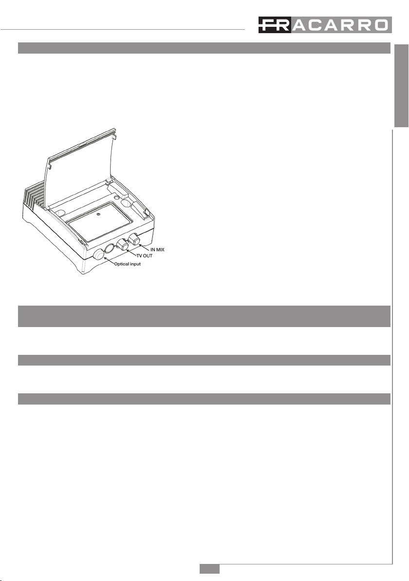
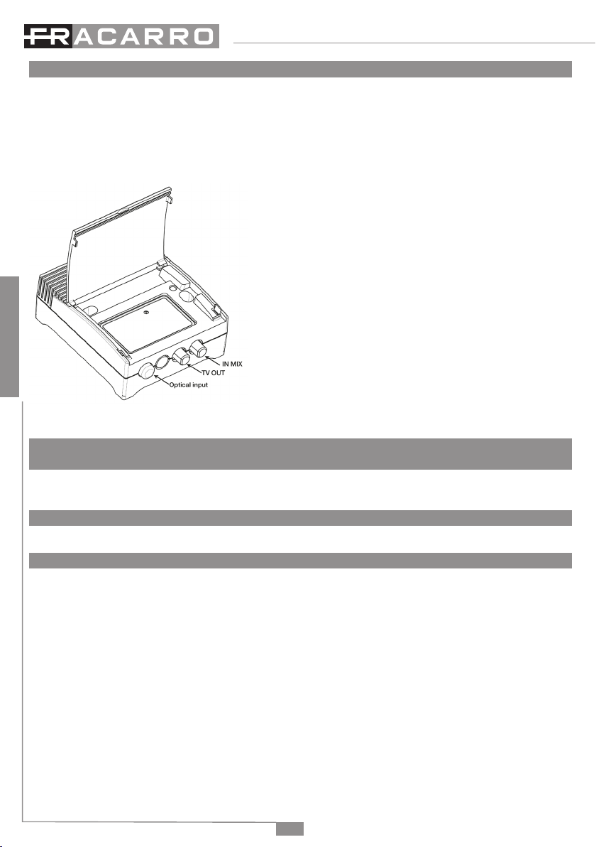
• Non guardare mai dentro ai connettori ottici del prodotto. La radiazione laser non è visibile ad
occhio nudo e quindi non è possibile prevenire un danno a lungo termine.
• Quando si lavora con i connettori ottici del partitore, controllare sempre che i laser di eventuali
trasmettitori ottici ad esso collegati, siano spenti.
• In accordo con la direttiva europea 2004/108/EC (EMC), il prodotto deve essere installato
utilizzando dispositivi, cavi e accessori che consentano di rispettare i requisiti imposti da tale
direttiva per le installazioni fisse.
• ATTENZIONE: Per evitare di ferirsi, questo apparecchio deve essere assicurato al pavimento/
la parete secondo le istruzioni di installazione
Messa a terra dell’impianto d’antenna
Il prodotto deve essere collegato all’elettrodo di terra dell’impianto d’antenna conformemente
alla norma EN 60728-11.
IMPORTANTE:
Solo personale addestrato e autorizzato può effettuare interventi di manutenzione sul prodotto.
In caso di guasto non tentate di ripararlo, altrimenti la garanzia non sarà più valida.
Non togliere mai il coperchio dell’alimentatore, parti a tensione pericolosa possono risultare
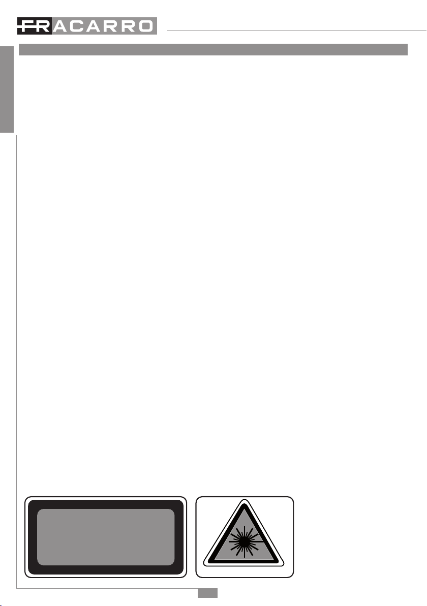
accessibili all’apertura dell’involucro. ATTENZIONE: radiazione laser invisibile. Non osservare
direttamente. Prodotto laser di CLASSE 1M
INVISIBLE LASER RADIATION
DO NOT VIEW DIRECTLY WITH
OPTICAL INSTRUMENTS
(MAGNIFIERS)
CLASS 1M LASER PRODUCT
LASER RADIATION

3
Italiano
2. DESCRIZIONE DEL PRODOTTO
Il ricevitore OPT-RX DT TV converte il segnale ottico in un’unica uscita RF, mettendo a disposizione
degli utenti il segnale TV terrestre e una polarità SAT con tutti i servizi e contenuti offerti dai
broadcaster, come se fossero direttamente connessi alla propria antenna.
Il prodotto è provvisto di alimentatore e va dunque collegato alla rete elettrica tramite l’apposito
cavo di alimentazione fornito in dotazione.
OPTICAL INPUT: connettore FC-PC di ingresso del
ricevitore ottico. In dotazione è presente una bretella
d’adattamento FC/APC-SC/APC.
TV OUT: 1 connettore F per uscita TV (87 ÷ 862MHz)
e SAT (950÷2150 MHz) 1 polarità, segnale associato
all’ingresso HH se viene utilizzato il trasmettitore OPT-TX
DT.
IN MIX: 1 connettore F per ingresso miscelante di
segnale da 5 a 2400 MHz.
LED alimentazione: acceso (verde) quando il
prodotto è alimentato.
TRIMMER regolazione livello del segnale in uscita (0-
20dB)
3. INSTALLAZIONE DEL PRODOTTO
3.1 Installazione
Il ricevitore OPT- RX DT TV può essere fissato a muro utilizzando i fori sotto al coperchio.
Si preveda lo spazio necessario per la corretta ventilazione del prodotto.
3.2 Alimentazione
Collegare il prodotto alla rete elettrica utilizzando l’apposito cavo di alimentazione fornito in
dotazione.
3.3 Collegamento fibra ottica
ATTENZIONE: Non è possibile effettuare un collegamento ottico diretto tra
il trasmettitore ottico e il ricevitore OPT-RX DT TV. Ciò è possibile solo utilizzando
attenuatori ottici di linea, in quanto la potenza massima in ingresso al ricevitore ottico non può
superare i -8dBm. Verificare il livello ottico del segnale sulla fibra, tramite un
misuratore ottico prima di collegarla al ricevitore.
Utilizzare le bretelle FC/APC-SC/APC per collegare il ricevitore ai dispositivi VOV e VOT tramite
opportuni adattatori.
Attenzione: Per preservare e proteggere le superfici di contatto dei connettori ottici è buona
regola non togliere le protezioni di bussole e ferule fino al momento della connessione o
dell’eventuale pulizia tramite appositi strumenti dedicati.
STRUZI

4
Italiano
PER L’UTILIZZO
4. ISTRUZIONI PER L’UTILIZZO
4.1 Dimensionamento di un impianto in fibra ottica
Il ricevitore OPT-RX DT TV garantisce un adeguato livello del segnale TV e SAT alla presa utente
se il segnale ottico al suo ingresso è compreso tra -8dBm e -14dBm ottici e
il segnale RF in ingresso al trasmettitore (OPT-TX DT, KTX o OPT-TX51) rispetta le indicazioni
riportate nel manuale del trasmettitore.
ATTENZIONE:
Non sono ammessi collegamenti diretti tra trasmettitore e OPT-RX DT TV, a meno
di non utilizzare opportuni attenuatori ottici di linea.
È indispensabile utilizzare un misuratore di segnale ottico per verificare il livello ottico d’ingresso al
ricevitore ed evitare di danneggiare il fotodiodo ricevente (potrebbe danneggiarsi se il segnale in
ingresso è superiore a 0dBm).
4.2 Livelli in uscita al ricevitore ottico
Il livello in uscita dal ricevitore ottico OPT-RX DT TV dipende dal numero di segnali trasmessi in
fibra e dall’attenuazione ottica della tratta. Si tenga conto che 1dB di perdita ottica equivale a 2dB
di attenuazione del livello elettrico (RF).
Di seguito vengono riportati alcuni livelli di riferimento massimi dei segnali in uscita al ricevitore
OPT-RX DT TV.
Nota: il livello del segnale in uscita può essere regolato tramite il trimmer di regolazione (0-20dB).
TV (DTT/CATV)
La potenza totale in uscita è pari a -29dBm (80dBµV) con 21dB di attenuazione ottica, per cui
meno multiplex vengono trasmessi, maggiore sarà il livello e la qualità del segnale in uscita.
Livello RF in uscita per MUX
Numero MUX Livello ottico al ricevitore -8dBm
(15dB attenuazione ottica)
Livello ottico al ricevitore -14dBm
(21dB attenuazione ottica)
40 76 dBµV 64 dBµV
16 81 dBµV 68 dBµV
8 83 dBµV 71 dBµV
4 86 dBµV 74 dBµV
Tab.1 indicazioni livelli di uscita all’OPT-RX DT - segnale TV.
Nota: 1dB ottico equivale a 2dB a livello elettrico (RF).
SAT
Il livello tipico del segnale SAT in uscita dell’OPT-RX DT TV è:
• 70dBµV per transponder con un livello ottico di -14dBm in ingresso al ricevitore (21dB di
attenuazione ottica)
• 82dBµV per transponder con un livello ottico di -8dBm in ingresso al ricevitore (15dB di
attenuazione ottica)
Attenzione: all’uscita del ricevitore è presente solo il segnale SAT di una polarità
FM e DAB
Il livello dei segnali FM e DAB deve essere inferiore di almeno 10dB rispetto ai segnali DVB-T o
DVB-C.
NOTA: i livelli dei segnali alle prese utenti devono rispettare i valori imposti dalla normativa EN50083-
7 (DTT: 45÷74dBuV - SAT: 47÷77dBuV). In alcuni casi sarà necessario attenuare il segnale RF in
uscita dal ricevitore o, se possibile, il segnale ottico al suo ingresso tramite componenti passivi
quali attenuatori ottici di linea.

5
Italiano
5. SPECIFICHE TECNICHE
OPT-RX DT TV
Fracarro code 270696
CONNECTORS
Optical input connector Type FC/PC /patch cable SC/APC
Input connector (for loop through) Type F female
Output connector Type F female
OUTPUTS
Output bandwidth MHz TV: 87 ÷ 862 SAT: 950 ÷ 2150
TV Output power level
(@-14dBm optical input power and no attenuation) dBµV 80 ± 5 (TV overall power)
TV Output: MER Performance dB ≥23 (with input MER≥30)
Sat Output power level (@-14dBm optical input power) dBµV 70 ± 5 (per transponder, with 35 trasponder)
Sat Output: MER Performance
dB
≥10 (with input MER≥15)
Output level adjustment (using trimmer) dB 0 ÷ 20 (attenuation)
Impedance Ω75
Return loss dB -10
Loop through loss dB <1,2 up to 862MHz <3 up to 2150MHz
Loop through bandpass MHz 5÷2400
Loop through DC pass NO
OPTICAL INPUT
Connector Type FC/PC
Optical fiber ITU-T G.652
Central wavelength nm 1310
Max optical input power dBm -8 (values exceeding this limit may damage device)
Min optical input power dBm -14
Optical return loss dB Max -50
POWER SUPPLY
Mains VAC, Hz 184 ÷ 264, 50 ÷ 60
Power consumption W 2,5 (@ -5 ÷ +50 ºC)
OTHER FEATURES
LED indicator Green light means module is powered
Operating temperature °C -5 ÷ 50
Compliance EN50083-2, EN60065

6
Italiano
6. ESEMPI TIPICI DI IMPIANTO
Alcuni schemi di esempio sono disponibili nelle ultime pagine del manuale e nel sito www.fracarro.com
7. CONFORMITA’ ALLE NORMATIVE EUROPEE
Il prodotto OPT-RX DT TV è conforme alle norme:
EN 50083-2 (direttiva europea 2004/108/EC – EMC)
EN 60065 (direttiva europea 2006/95/EC – LVD)

7
English
1. SAFETY WARNINGS
The product must be installed by a qualified engineer, according to the local safety standards and
regulations.
The product is classified as Class II, in accordance with EN 60065, and for this reason it doesn’t
need to be connected to the protective earth (PE) of the mains supply.
Installation warnings
• Only use the original power cable (adaptor) supplied and install the product so that the mains
plug is easily accessible.
• The product must not be exposed to dripping or splashing liquids and so must be installed
indoors in a dry place.
• Humidity and condensation could damage the product. In case of condensation, wait until
the product is dry before using it.
• Don’t install the product above or close to heat sources, in dusty places or where it might
come into contact with corrosive substances.
• Keep the product away from heat sources to prevent some parts or components of the unit
to catching fire.
• To fix the product to the wall use suitable expansion bolts.
• Leave enough space around the product housing to ensure sufficient ventilation.
“An excessive operating temperature and/or excessive heat may affect the performance
and the lifespan of the product.”
• Never look inside the product’s optical connectors. The laser radiation is not visible with the
naked eye and therefore it is not possible to prevent long term damage.
• When working with the splitter’s optical connectors make sure that the lasers of any optical
transmitters connected to it are switched off.
• In accordance with the European Directive 2004/108/EC (EMC), the product must be
installed using devices, cables and accessories that comply with this directives requirements
for fixed installations.
• WARNING: To prevent injury, this product must be secured to the floor / wall in accordance
with the installation instructions.
Aerial system earth connection
The unit must be connected to the ground electrode of the antenna installation according to the
standard EN60728-11.
IMPORTANT:
Only trained and authorised personnel can open the product. In case of failure, do not try to repair
the product; otherwise the guarantee will no longer be valid.
Never remove the cover of the power supply: dangerous voltage levels may be accessible.
CAUTION: Invisible laser radiation. Do not look at it directly. CLASS 1M laser product
INVISIBLE LASER RADIATION
DO NOT VIEW DIRECTLY WITH
OPTICAL INSTRUMENTS
(MAGNIFIERS)
CLASS 1M LASER PRODUCT
LASER RADIATION

8
English
2. PRODUCT DESCRIPTION
OPT-RX DT TV converts the optical signal into a single RF output, providing users with TV terrestrial
signal and 1 SAT polarity with all the services and content offered by broadcasters, as if they were
directly connected to the antenna.
The product is equipped with power supply and should be connected to the mains using the
appropriate power cord supplied.
OPTICAL INPUT: optical receiver FC-PC input
connector. Strap adaptation FC/APC - SC/APC supplied.
TV OUT: 1 F connettor for TV output (87 ÷ 862MHz) and
SAT (950÷2150 MHz) 1 polarity, associated signal to HH
input if OPT-TX DT transmitter is used.
IN MIX: 1 F connettor for each signal mixed input from
5 up to 2400 MHz.
POWER ON LED: On (green) to show the product is
turned on.
TRIMMER output signal regolation level (0-20dB)
3. PRODUCT INSTALLATION
3.1 Installation
OPT- RX DT TV receiver can be wall mounted using the holes under the cover. Provide the
necessary space for proper ventilation.
3.2 Power supply
Connect the product to the power supply using the appropriate power cord supplied.
3.3 Fibre optic connection
ATTENTION: direct connections between optical transmitter and OPT-RX DT TV
are not allowed. This is possible only using the appropriate line optical attenuators because
the maximum input power to the optical receiver can not exceed-8dBm. Check the level of
the fibre optical signal using an optical power meter before connecting it to the
receiver.
Use the straps FC/APC - SC/APC to connect the receiver to the VOV and VOT devices using
appropriate adapters.
Attention: To preserve and protect the contact surfaces of the optical connectors it is a good
rule not to remove the protections of compasses and splints before the connection time or the
cleaning, using special tools.

9
English
I PER L’UTILIZZO
4. USER’S INSTRUCTIONS
4.1 Dimensioning a Fibre Optic system
RX DT OPT-TV receiver ensures an adequate level of TV and SAT signal to the socket if the
optical signal at its input is between -14dBm and-8dBm and transmitter input RF
signal (TX DT-OPT, KTX or OPT-TX51) respects the transmitter manual instructions.
ATTENTION:
Direct connections between transmitter and OPT-RX DT TV receiver are not
allowed, unless using appropriate line optical attenuators.
It is essential to use an optical meter to check the input level at the optical receiver and to prevent
the photodiode receiver damage (it could be damaged if the input signal is greater than 0 dBm).
4.2 Output levels to the optical receiver
The output level depends on the number of signals transmitted through the fibre and on the
oprical attenuation of the section. Please note that 1dB optical loss is equivalent to 2 dB of
attenuation at the electrical level (RF).
Below some reference levels are given for the output signals to the OPT-RX DT TV receiver
Note: the level of the output signal can be adjusted using the trimmer (0-20dB).
TV (DTT/CATV)
The total output power is equal to-29dBm (80dBµV) with 21dB of optical attenuation, this means
that the lower is the number of multiplexes transmitted, the higher the output quality and signal
level will be.
RF output level per MUX
No. of MUX Receiver optical level -8dBm
(15dB optical attenuation)
Receiver optical level -14dBm
(21dB optical attenuation)
40 76 dBµV 64 dBµV
16 81 dBµV 68 dBµV
8 83 dBµV 71 dBµV
4 86 dBµV 74 dBµV
Output levels to the OPT-RX DT TV - TV signal.
Nota: 1 optical dB equal 2dB at electric level (RF).
SAT
The typical output SAT signal level of the OPT-RX DT TV is:
• 70dBµV for transponder with an optical level of-14dBm at the receiver input (optical
attenuation 21dB)
• 82dBµV for transponder with an optical level of-8dBm at the receiver input (15 dB of optical
attenuation)
Warning: the output of the receiver is only the SAT signal of one polarity
FM and DAB
The level of FM and DAB signals must be at least less than 10 dB compared to DVB-T or DVB-C.
NOTE: the sockets signal levels must respect the values required by the regulations EN50083-7
(DTT: 45 ÷ 74dBµV - SAT: 47 ÷ 77dBµV). In some cases it will be necessary to attenuate the RF
receiver output signal or, if possible, the input optical signal through passive components such as
line optical attenuators.

10
5. TECHNICAL SPECIFICATIONS
OPT-RX DT TV
Fracarro code 270696
CONNECTORS
Optical input connector Type FC/PC /patch cable SC/APC
Input connector (for loop through) Type F female
Output connector Type F female
OUTPUTS
Output bandwidth MHz TV: 87 ÷ 862 SAT: 950 ÷ 2150
TV Output power level
(@-14dBm optical input power and no attenuation) dBµV 80 ± 5 (TV overall power)
TV Output: MER Performance dB ≥23 (with input MER≥30)
Sat Output power level (@-14dBm optical input power) dBµV 70 ± 5 (per transponder, with 35 trasponder)
Sat Output: MER Performance
dB
≥10 (with input MER≥15)
Output level adjustment (using trimmer) dB 0 ÷ 20 (attenuation)
Impedance Ω75
Return loss dB -10
Loop through loss dB <1,2 up to 862MHz <3 up to 2150MHz
Loop through bandpass MHz 5÷2400
Loop through DC pass NO
OPTICAL INPUT
Connector Type FC/PC
Optical fiber ITU-T G.652
Central wavelength nm 1310
Max optical input power dBm -8 (values exceeding this limit may damage device)
Min optical input power dBm -14
Optical return loss dB Max -50
POWER SUPPLY
Mains VAC, Hz 184 ÷ 264, 50 ÷ 60
Power consumption W 2,5 (@ -5 ÷ +50 ºC)
OTHER FEATURES
LED indicator Green light means module is powered
Operating temperature °C -5 ÷ 50
Compliance EN50083-2, EN60065
7. EUROPEAN DIRECTIVES CONFORMITY
The product OPT-RX DT TV complies with the standard:
EN 50083-2 (European directive 2004/108/EC - EMC)
EN 60065 (uropean directives EMC, 2006/95/EC - LVD)
English

11
Schema con trasmettitore KTX e ricevitori OPT-RX DT TV
Scheme with KTX transmitter and OPT-RX DT TV receivers
ESEMPI TIPICI DI IMPIANTO
APPLICATION EXAMPLE
Attenzione:
• L’indicazione delle antenne, del centralino o eventuali preamplificatori riportati negli schemi è
puramente indicativa in quanto la scelta dipende esclusivamente dalla tipologia del segnale
ricevuto nella zona di realizzazione dell’impianto.
• I livelli alle prese dipendono dai segnali trasmessi e dal livello ottico in ingresso all’OPT-RX DT
(vedi capitolo 4).
• I valori ottici riportati negli schemi sono calcolati sulla base dei valori medi di specifica dei
componenti passivi utilizzati.
Warning:
• The choice of antennas, dishes and multiband amplifiers are shown purely as an indication of a
typical example. Care must be taken to ensure that the correct equipment is used to optimise
both signal strength and quality based on the geographical location of the intended installation.
• RF outlet levels at the receivers are dependant on the number of transmitted signals over the
fibre and to the optical input level at the receiver (see chapter 4).
• Optical levels shown in the following designs are calculated using the typical attenuation
values for the passive components used.

Schema con trasmettitore OPT-TX DT e ricevitori misti
Scheme with OPT-TX DT transmitter and different receivers
3IS601 - 8/2013
Fracarro Radioindustrie S.p.A.
Via Cazzaro n.3 - 31033 Castelfranco Veneto (TV) - ITALIA - Tel: +39 0423 7361 - Fax: +39 0423 736220 - Società a socio unico.
Fracarro France S.A.S.
7/14 rue du Fossé Blanc Bâtiment C1 - 92622 Gennevilliers Cedex - FRANCE Tel: +33 1 47283400 - Fax: +33 1 47283421
Fracarro (UK) - Ltd
Unit A, Ibex House, Keller Close, Kiln Farm, Milton Keynes MK11 3LL UK - Tel: +44(0)1908 571571 - Fax: +44(0)1908 571570
Fracarro Tecnologia e Antenas de Televisao Lda
Rua Alexandre Herculano, n°1-1°B, Edifício Central Park 2795-242 Linda-a-Velha PORTUGAL - Tel: +351 21 415 68 00 - Fax +351 21 415 68 09
Fracarro Polska Sp.z o.o.
ul. Płowiecka 109A 04-501 Warszawa Polska Tel: +48228120748 Fax: +48228126527
Garantito da/ Guaranteed by/ Garanti par/ Garantizado por/ Garantido por/ Garantiert durch/ Zajamčena od/ Garantirano od/
Garantovano od/ Gwarantowane przez / Εγγυημένο από/ Гарантировано
Fracarro Radioindustrie S.p.A., Via Cazzaro n. 3, 31033 Castelfranco Veneto (Tv) – Italy
This manual suits for next models
1
Table of contents
Languages:
Other Fracarro Cables And Connectors manuals