Fracarro HEADLINE SIG7600-HTX User manual

EN50083-2
EN60065
ISTRUZIONI PER L’USO
OPERATING INSTRUCTIONS
INSTRUCTIONS D’EMPLOI
INSTRUCCIONES DE USO
INSTRUÇÕES DE FUNCIONAMENTO
BETRIEBSANLEITUNG
SIG7600-HTX
TRASMETTITORE OTTICO - OPTICAL TRANSMITTER
ÉMETTEUR OPTIQUE - TRANSMISOR ÓPTICO
TRANSMISSOR ÓTICO - OPTISCHER SENDER

2
ITALIANO
INDICAZIONI PER LA SICUREZZA
Condizioni ambientali: Questa apparecchiatura è progettata per essere installata in ambienti
chiusi. Non installare in luoghi in cui vi siano vapori corrosivi o condizioni ambientali critiche e in
aree considerate pericolose.
Caratteristiche del sito di installazione: L’installazione delle apparecchiature deve essere
effettuata da un tecnico specializzato in un luogo asciutto e con le seguenti caratteristiche:
- l’ambiente non deve essere classificato come ad alto rischio di incendio
- non ci deve essere una grande concentrazione di particelle sospese
- il sistema deve essere posizionato in una stanza privata e protetta da possibili intrusioni
- il sistema non deve essere esposto a raggi ultravioletti
- il sito deve essere accessibile dal personale per la manutenzione
- il sito deve essere asciutto, con basso livello di umidità
- il sito deve garantire lo spazio sufficiente per i cavi e la naturale ventilazione del sistema
- non installare all’interno di sistemi riscaldamento o condizionamento
- non installare dentro le tubazioni idrauliche o in aree per prevenzione incendi (vie di fuga,
ascensori, tunnel, uscite di emergenza) che devono garantire gli standard di sicurezza definiti
- i prodotti devono essere accessibili per controlli e manutenzione
- verificare che la temperatura ambiente non superi i limiti consentiti
Collegamenti alla corrente elettrica: Il collegamento alla corrente elettrica deve essere eseguito
da personale idoneo e competente in conformità alle locali normative di sicurezza.
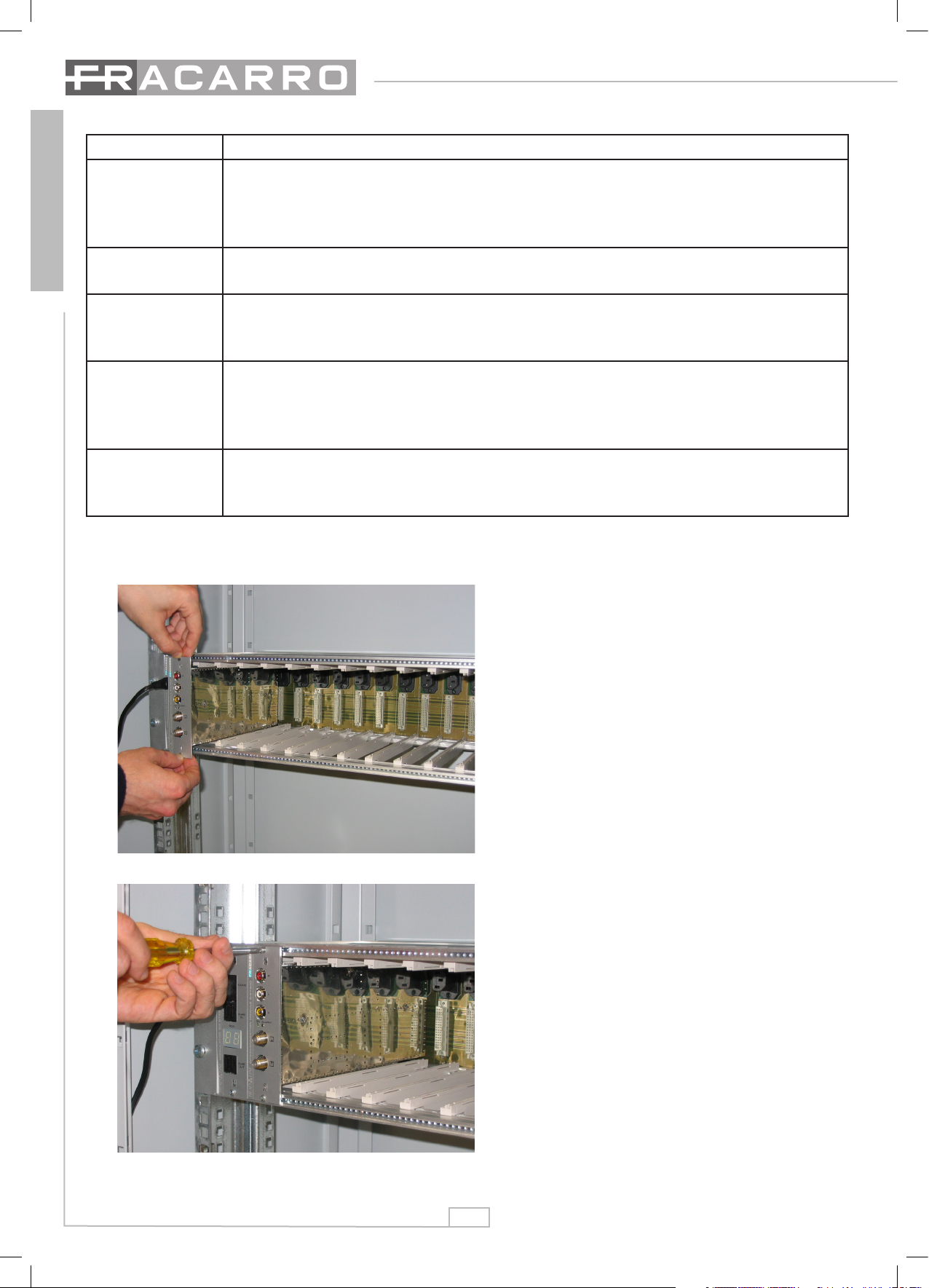
Sicurezza e precauzioni: Il prodotto è dichiarato di Classe II, in conformità alla norma EN
60065, e deve essere installato nel cestello della serie Headline. Non deve mai essere alimentato
direttamente con un cavo di alimentazione tripolare. In nessun caso deve essere collegato alla
terra di protezione (PE) della rete di alimentazione. Il trasmettitore ottico SIG7600-HTX include un
modulo laser ed è pertanto classificato ed etichettato come apparecchiatura di classe 3B secondo
la norma EN60825-1. Durante le attività di installazione è necessario seguire le regole seguenti:
- non guardare mai dentro l’uscita del connettore ottico del trasmettitore quando è acceso
(la lunghezza d’onda del laser non è visibile ad occhio nudo, il che significa che un danno a lungo
termine non è immediatamente percepibile).
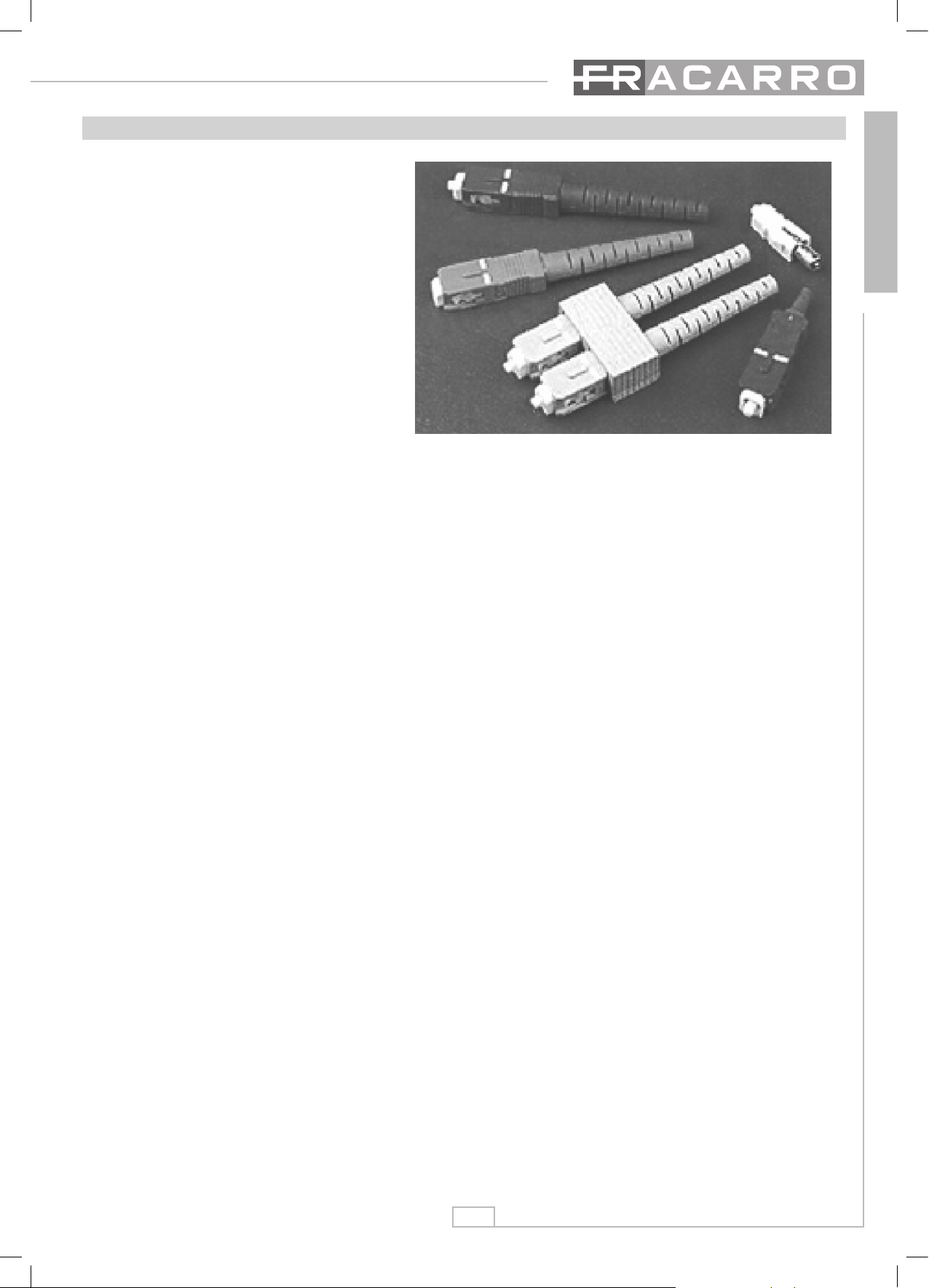
- quando si lavora con i connettori ottici, controllare sempre che i laser siano spenti.
Messa a terra dell’impianto d’antenna: La centrale in cui è installato il prodotto deve essere
collegata all’elettrodo di terra dell’ impianto d’antenna conformemente alla norma EN50083-1, par.
10. Si raccomanda di attenersi alle disposizioni della norma EN 50083-1 e di non collegare la
centrale alla terra di protezione della rete elettrica di alimentazione.
Etichette di avvertenza
Simbolo di pericolo (secondo EN 60825-1) per apparecchi
laser.
ATTENZIONE! radiazione laser. Non guardare dentro il
fascio o direttamente con strumenti ottici.
Prodotto laser di CLASSE 3B.

3
ITALIANO
DESCRIZIONE DEL TRASMETTITORE
Trasmettitore in fibra ottica SIG7600-HTX . Converte un segnale elettrico in segna-
le ottico e lo trasmette nella seconda finestra (1310nm). Permette inoltre la trasmis-
sione delle bande TV 47-862MHz e SAT 950-2150MHz con una potenza di 13mW.
Sul pannello frontale sono presenti i connettori F (ingresso RF) e il connettore
SC/APC (uscita fibra ottica). Vedi fig. 1.
INGRESSO TV + SAT
USCITA OTTICA
LED VERDE “ON“
LED ROSSO “BOARD TEMP“
LED VERDE “LASER ON“
Fig. 1
LED ROSSO “OVER CURRENT“
LED ROSSO “LASER TEMP“
Per rendere operativo il trasmettitore ottico SIG7600-HTX eseguire le seguenti ope-
razioni:
inserire il trasmettitore nel cestello HEAD LINE correttamente alimentato e atten-
dere alcuni secondi;
utilizzando il modulo TPE, entrare nel menù SETUP CENTRALE -> SCAN CEN-
TRALE;
avvenuta l’acquisizione dei moduli, entrare in SETUP CENTRALE -> NAVIGA-
ZIONE -> XX SIG7600-HTX (dove XX indica la posizione in cui e’ inserito);
alla voce CONTROLLO LASER, impostare la modalità di funzionamento deside-
rata:
– OFF: il modulo laser e’ spento;
– ON: il diodo laser e’ attivo e funzionante;
– AUTO: modalità diagnostica che disattiva il laser al presentarsi di una
anomalia (calo di tensione di rete, temperatura eccessiva ecc.). Si noti
che per avere il laser attivo in modalità AUTO, bisogna passare per la modalità
ON (passando da OFF ad AUTO il laser rimane spento).
IMPORTANTE: una volta selezionata la modalità desiderata, memorizzarla con il
tasto <M> del TPE.
1.
2.
3.
4.
INIZIALIZZAZIONE DEL TRASMETTITORE
Etichetta indicante l'apertura laser, fissata vicino ai connettori ottici.

4
ITALIANO
Dopo aver installato il modulo
provvedere ad avvitare le viti che
si trovano nel relativo sacchetto
accessori.(vedi Fig.3)
L’installazione è di tipo “plug &
play”, il modulo è gia operativo e
funzionante.
Inserire i moduli nelle guide
schede e spingerli delicatamente
in modo da agganciarli al back-
panel.(vedi Fig.2)
Stato LED Significato
Module ON
Verde
Acceso: modulo funzionante correttamente.
Spento: modulo non alimentato.
Lampeggiante: il modulo è stato interrogato dal modulo di interconnessione ed
è in fase di programmazione.
Laser ON
Verde
Acceso: il laser è attivato e sta emettendo radiazione luminosa coerente.
Spento: il laser non è attivato, nessuna radiazione è emessa dal modulo.
Over current
Rosso
Acceso: la corrente che alimenta il diodo laser sta eccedendo i limiti di corretto
funzionamento. Contattare l’assistenza tecnica.
Spento: Nessun malfunzionamento.
Laser temp
Rosso
Acceso: il sistema di raffreddamento del diodo laser non sta funzionando
correttamente, possibile degrado delle prestazioni del modulo. Contattare
l’assistenza tecnica.
Spento: Nessun malfunzionamento.
Board temp
Rosso
Acceso: il modulo si trova al di fuori del range di temperatura di lavoro previsto.
Rimuovere la causa di surriscaldamento o contattare l’assistenza tecnica.
Spento: Nessun malfunzionamento.
Fig. 2
Fig. 3
Il modulo si installa sul cestello della serie Headline come da foto seguenti.

5
ITALIANO
Fig. 4.2
Dopo aver installato il modulo, utilizzare il TPE per la programmazione.
Collegare il TPE a uno dei moduli di interconnessione della centrale, aspettare
che il programmatore effettui la mappatura di tutti i moduli e poi procedere con la
ricerca del modulo da programmare (maggiori dettagli sulle istruzioni del cestello
headline).Il SIG7600-HTX che si sta programmando ha il led verde che lampeggia.
Il modulo di interconnessione della riga che contiene il modulo che si sta program-
mando ha il display con il numero lampeggiante.
Nota Bene: Per memorizzare i dati impostati premere il tasto S del TPE. Se
non si preme il tasto S entro i 5 minuti dell’ultima modifica i dati impostati
verranno persi.
Per maggiori dettagli vedere le istruzioni del cestello headline.
Seguono i menù di programmazione.
Per la rimozione del modulo utilizzare le maniglie in dotazione al cestello Headline.
Per facilitare la gestione e la manutenzione dei moduli si consiglia di utilizzare le
etichette che si trovano nell’imballo del cestello Headline per mostrare la posizione
dei moduli all’interno della riga.
Attaccare l’etichetta appartenente alla lista “numero modulo” con il numero corri-
spondete alla posizione del ricevitore in alto a destra. (vedi Fig. 4.1 e 4.2)
NUMERO MODULI/ MODULE NUMBER
1 2 3 4 5 6 7 8 9 10 11
Fig. 4.1

6
ITALIANO
1.0 MENU
SPECIFICHE TECNICHE
Frequenza di ingresso 47 ÷ 862MHz, 950 ÷ 2150MHz
Impedenza 75ohm
Max livello TV 97dBµV (2 toni IM3 ≤-60dBc)
85dBµV 42 portanti (CSO, CTB ≤-60dBc)*
Max livello SAT 92dBµV (2 toni IM3 ≤-35dBc)
Return Loss 10dB
Lunghezza d’onda 1310 ± 10nm
Potenza ottica 13mW (11 dBm)
Piattezza in banda 47÷862MHz ±1 dB
Piattezza in banda 950÷2150MHz ± 2 dB
Alimentazione 220 - 240V~ 50-60Hz
Consumo 6,5 W
Temperatura di lavoro - 10 ÷ + 45°C
Conformità alle norme EN50083-2, EN60065
* Conforme standard CENELEC.

7
ITALIANO

8
ITALIANO
Questa guida premette di ottenere il massimo rendimento dal
vostro sistema ottico FRACARRO
FASE 1: calcolare il budget ottico. Usare il primo schema per calcolare il proprio budget
ottico (perdita ottica tra HTX e KRX). Aggiungere il numero corretto di dB corrispon-
denti al numero di split che si sta applicando e aggiungere 0,4dB per ogni chilometro
di fibra lungo la linea (oppure 0,25dB se si sta usando un trasmettitore a 1550nm). Per
esempio se si ha HTX – KSP1_2 – KSP1_4 – 8km di fibra – KRX, il budget ottico sarà:
7 + 3.5 + 0.4 x 8 = 13.8dB (≈14dB).
Attenzione: connettori non puliti possono influenzare negativamente il budget
ottico! Pulirli con cura!
FASE 2: determinare il livello di ingresso ottimale.
Il punto critico è sempre la trasmissione di ca-
nali terrestri analogici. Supponiamo di doverne
trasmettere 40. Se l’apparecchiatura head-end lo
consente, impostare la potenza sul valore suggeri-
to dalla tabella a sinistra (circa 85dBµV, riferendosi
alla fila del canale 42); altrimenti assicurasi di non
superarla. Come regola generale, la potenza del
transponder digitale deve essere più bassa di
10dB-15dB dei canali analogici: per esempio, se
si hanno 30 transponder SAT, l’impostazione otti-
male è di 70-75dBµV per transponder.
FASE 3: calcolare SNR e il livello di usci-
ta. Considerando un budget ottico di 14dB
l’SNR può essere letto nella intersezione
della colonna del livello di ingresso e nel-
la diagonale del budget ottico. Nell’esem-
pio precedente, l’SNR per canali analogici
risulta 51dB. Il livello di uscita può esse-
re letto movendosi a sinistra fino a che si
incrocia l’ultima colonna: nell’esempio è
82dBµV per ogni canale analogico.
Per transponder digitali, si applicano consi-
derazioni simili. Se si imposta sia DTT che
la potenza del transponder SAT a 10dB in
meno rispetto agli analogici terrestri, anche il livello di uscita sarà inferiore a 10dB, e
SNR sarà al di sotto di 10dB. Comunque per i segnali digitali a 25dB di SNR è ancora
un buon valore!
Ulteriori esempi sono riportati nella guida utente: si raccomanda di leggerli at-
tentamente!

9
ITALIANO
Precauzione: scollegare la
corrente elettrica prima di pulire i
connettori ottici.
I connettori ottici sono simili alle
lenti degli occhiali e quindi il loro
rendimento viene compromesso
dalla polvere, dalle particelle,
dal grasso delle dita e dai graffi.
La superficie della ferula del
connettore può essere verificata
tramite un microscopio.
SC-APC connettore e adattatore
Per pulire un connettore ottico si proceda come segue:
Aprire le connessioni.
Applicare una goccia di liquido pulente (alcool puro) sul bordo della ferula, poi
togliere lo sporco con uno spruzzo
Prima di inserire nuovamente tutti i connettori, pulire l’adattatore applicando una
goccia di liquido pulente nel foro centrale e rimuoverlo immediatamente con uno
spruzzo.
Inserire nuovamente i connettori nell’adattatore evitando qualsiasi contatto fisico
delle ferule con le dita o qualsiasi altra superficie.
Note :
- i connettori /adattatori devono sempre essere protetti dai loro coperchi.
- Non aprire mai i collegamenti in ambienti umidi o polverosi
- usare solo alcool puro per la pulizia.
- i connettori graffiati possono danneggiare gli altri connettori; devono essere
sostituiti.
1.
2.
3.
4.
PULIZIA DEL COLLEGAMENTO OTTICO

10
ENGLISH
SAFETY INSTRUCTIONS
Environmental conditions: This equipment is designed to be installed indoors. Do not install it in
places where corrosive vapors or critical environmental conditions are present nor in dangerous
areas.
Characteristics of the installation room: The installation of the unit must be performed by a
specialized technician and in a dry room with the following characteristics:
- the environment must not be classified as a high risk of fire
- there must not be high concentration of suspended particles
- the system must be placed in a private room protected from intruders
- the system must not be exposed to ultraviolet rays
- the site must be accessible to the maintenance personnel
- the room must be dry with a low humidity level
- the room must have sufficient space for cables and system ventilation
- do not install inside heating or air-conditioning systems
- do not install inside pipes or in areas for fire prevention (such as ways out, elevators, tunnels,
emergency exits) since they have to ensure defined safety standards
- the products must be accessible for controls and maintenance
- check that the room temperature does not exceed the limits
Connection to the power: The connection to the power must be performed by trained and skilful
personnel according to local safety norms.
Safety and precautions: the product of Class II, in conformity with the EN 60065 regulation,
must be installed in the Headline series basket. It must never be directly supplied by a three-polar
supply cable. In no circumstance should it be connected to the protection ground (PE) of the power
supply network. The SIG7600-HTX optical transmitter includes a laser module and, therefore, it is
classified and labeled as a 3B class equipment according to the EN60825-1 regulation. During the
installation, follow the following instructions:
- never look inside the optical connector output when it is On (the wavelength of the laser is not
visible by the eye; therefore, long-term damage is not immediately felt).
- when working with optical connectors, always control when the laser is off.
Grounding of the antenna: The exchange to which the unit is installed must be connected to the
ground electrode of the antenna installation according to the EN50083-1 regulation, paragraph 10.
We recommend that you follow the EN 50083-1 regulation and to not connect the exchange to the
protection ground of power supply network.
Warning labels
Danger symbols (according to EN 60825-1) for laser
equipment.
WARNING! Laser radiation. Do not look inside the beam
or directly at it with optical instruments.
Laser product of 3B CLASS.

11
ENGLISH
PRODUCT DESCRIPTION
SIG7600-HTX optical fiber transmitter. It converts the electrical signal in an optical
signal and transmits it in the second window (1310nm). Moreover, it allows the tran-
smission of the 47-862MHz TV band and the 950-2150MHz SAT band with 13mW
power. On the front panel are the F connectors (RF input) and the SC/APC (optical
fiber output) connector. See fig. 1.
TV + SAT INPUT
OPTICAL OUTPUT
GREEN LED: “ON“
RED LED : “BOARD TEMP“
GREEN LED: “LASER ON“
Fig. 1
RED LED : “OVER CURRENT“
RED LED : “LASER TEMP“
Follow the following instructions to make the SIG7600-HTX optical transmitter opera-
tive:
insert the transmitter in the HEAD LINE basket and power supply it properly; wait for
few seconds;
use the TPE module to enter the EXCHANGE SETUP menu -> SCAN EX-
CHANGE;
after the acquisition of the modules, enter EXCHANGE SETUP -> NAVIGATION ->
XX SIG7600-HTX (where XX shows the position where it is inserted);
set the desired operational mode with the LASER CONTROL item:
– OFF: the laser module is Off;
– ON: the laser diode is active and operative;
– AUTO: diagnostics mode, which deactivates the laser if an anomalous event
occurs (drop of tension, excessive temperature, etc.). Take note that the laser is
activated in AUTO mode if the Mode On is on (passing from Off to AUTO, the la-
ser remains off).
IMPORTANT: after choosing the mode, store it with the <M> key of TPE.
1.
2.
3.
4.
TRANSMITTER INITIALIZATION
The label shows the laser opening and is fixed close to the optical
connectors.

12
ENGLISH
After installing the module attach
it to the mounting rack using the
screws supplied in the accessory
bag. (see Fig 3)
Installation is “plug and play” so
the module is now working.
Insert the modules between the
guides and push them back care-
fully until they are in contact with
the back panel. (see Fig.2)
Stato LED Meaning
Module ON
Green
On : the module is operating properly
Off: the module is not supplied.
Flashing : the module has been interrogated by the interconnection module and
is programming.
Laser ON
Green
On : the laser is activated and is emitting a luminous radiation.
Off: the laser is not activated; no radiation emits from the module
Over current
Red
On: the power that supplies the laser diode is exceeding the limits of proper
working. Contact technical assistance.
Off: no malfunctioning.
Laser temp
Red
On: the cooling system of the laser diode is not working properly; the module
performances might have worsened. Contact technical assistance.
Off: no malfunctioning
Board temp
Red
On: the module is out of the range of operational temperature. Remove the
cause of overheating or contact technical assistance.
Off: no malfunctioning
Fig. 2
Fig. 3
The modules are installed using the 19” mounting rack fot the Headline range as
shown in the following photos.

13
ENGLISH
Fig. 4.2
After installing the modules use the TPE to program them.
Connect the TPE to one of the HEADEND’s interconnecting modules, wait until the
TPE checks all the modules and then start the search for the module to be program-
med.
The green LED of the module being programmed blinks. The interconnecting module
of the row being programmed displays a blinking number.
Important: Push the S button on the TPE to save the set parameters. If you do
not push the S button within 5 minutes of the last change the data set will be
lost.
For more details see “rack mounting” operating instructions.
The modulators programming menu is shown below.
To remove the module use the handles by the mounting rack. (For more details see
“rack mounting” operating instructions).
For maintenance and management of the modules it is recomended that the labels
supplied in the Headline mounting rack box are used showing the position of the mo-
dule in the row and the programmed output channel.
Stick the label on the top right side of the module from the “MODULE NUMBER”
sheet showing the corresponding positon of the modulator. (see Fig. 4.1 and 4.2)
Fig. 4.1 MODULE NUMBER

14
ENGLISH
1.0 MENU
TECHNICAL SPECIFICATIONS
Input frequency 47 ÷ 862MHz, 950 ÷ 2150MHz
Impedance 75ohm
Max TV level 97dBµV (2 tones IM3 ≤-60dBc)
85dBµV 42 carriers (CSO, CTB ≤-60dBc)*
Max livello SAT 92dBµV (2 tones IM3 ≤-35dBc)
Return Loss 10dB
Wavelength 1310 ± 10nm
Optical power 13mW (11 dBm)
Flatness in 47÷862MHz band ±1 dB
Flatness in 950÷2150MHz band ± 2 dB
Power Supply 220 - 240V~ 50-60Hz
Consumption 6,5 W
Operating temperature - 10 ÷ + 45°C
In Conformity with EN50083-2, EN60065
* Complying with standard CENELEC.

15
ENGLISH

16
ENGLISH
This guide should be used in order to obtain optimal
performance from your FRACARRO optical system.
STEP 1: calculating optical budget. Use the first diagram to calculate your optical bud-
get (optical loss between HTX and KRX). Add the correct number of dB corresponding
to the number of splits you’re applying, and add 0.4dB for each kilometer of fiber along
the trunk (or 0.25dB if you’re using a 1550nm transmitter). For example, if you have:
HTX – KSP1_2 – KSP1_4 – 8km of fiber – KRX, your optical budget will be: 7 + 3.5 +
0.4 x 8 = 13.8dB (≈14dB).
WARNING: unclean connectors may affect your optical budget! Clean them care-
fully!
STEP 2: determining optimal input level. The criti-
cal point is always the transmission of analog
terrestrial channels. Let’s suppose we must tran-
smit 40 of them.If your head-end equipment allows
you to do this, then, set their power to the value
suggested by the table on the left (about 85dBµV,
referring to the 42ch row); otherwise, make sure
you aren’t exceeding it. As a general rule, digital
transponders’power must be 10dB-15dB lower
than analog channels: for example, if you have
30 SAT transponders, their optimal setting is 70-
75dBµV per transponder.
STEP 3: calculating SNR and output level.
Considering an optical budget of 14dB, the
SNR can be read in the intersection of the
input level column and the optical budget
diagonal. In the previous example, the SNR
for analog channels results 51dB. Output
level can be read moving left until we cross
last column: in the example, it’s 82dBµV for
each analog channel.
For digital transponders, similar considera-
tions apply. If you set either DTT and SAT
transponders’ power 10dB lower than ana-
log terrestrial’s, output level will be 10dB lower as well, and SNR will be 10dB worst.
However, for digital signals 25dB of SNR is still a good value!
Further examples are reported in the user’s guide: we recommend to read them
carefully!

17
ENGLISH
Warning : disconnect the
electrical power before cleaning
the optical connectors.
Optical connectors are similar to
glasses lenses and, therefore,
their performance is decreased
by dust, particles, finger grease
and scratches. The surface of
the ferule can be checked with a
microscope.
SC-APC connector and adapter
To clean the optical connector, follow the following instructions:
Open the connections.
Apply one drop of a cleansing agent (pure alcohol) on the ferule edge and then
remove dust with a spray.
Before inserting all of the connectors, clean the adapter by applying a drop of a
cleansing agent in the central hole and then remove it immediately with a spray.
Insert all connectors in the adapter, avoiding any type of physical contact of the
ferules with the fingers or any other surface.
Notes :
- connectors/adapter must always be protected by their covers.
- Never open the connections in humid or dusty rooms
- use only pure alcohol for cleaning operations.
- scratched connectors can damage other connectors; therefore, they must be
replaced.
1.
2.
3.
4.
CLEANLINESS OF OPTICAL LINK

18
FRANÇAIS
INSTRUCTIONS DE SECURITE
Conditions environnementales: cet appareil est conçu pour être installé dans des endroits
fermés. Ne pas l’installer dans des endroits présentant des vapeurs corrosives ou des conditions
environnementales critiques et dans des zones considérées comme dangereuses.
Caractéristiques du site d’installation: les appareils doivent être installés par un technicien
spécialisé dans un endroit sec présentant les caractéristiques suivantes:
- le lieu ne doit pas être classé à haut risque d’incendie
- il ne doit pas y avoir une grande concentration de particules en suspension
- le système doit être placé dans une pièce privée et protégée contre de possibles intrusions
- le système ne doit pas être exposé aux rayons ultraviolets
- le site soit être accessible au personnel pour l’entretien
- le site doit être sec, avec un faible niveau d’humidité
- le site doit garantir l’espace suffisant pour les câbles et la ventilation naturelle du système
- ne pas installer le transmetteur à l’intérieur de systèmes de chauffage ou de climatisation
- ne pas installer le transmetteur dans les tuyaux hydrauliques ou dans des zones pour la prévention
des incendies (voies de fuite, ascenseurs, tunnels, sorties de secours) qui doivent garantir les
standards de sécurité indiqués
- les produits doivent être accessibles pour les contrôles et l’entretien
- vérifier que la température ambiante ne dépasse pas les limites indiquées
Connexions au courant électrique: la connexion au courant électrique doit être effectuée par le
personnel spécialisé et compétent conformément aux normes de sécurité en vigueur.
Sécurités et précautions: le produit est déclaré comme appartenant à la Classe II, en conformité
avec la norme EN 60065 et doit être installé dans le panier de la série Headline. Il ne doit jamais être
alimenté directement avec un câble d’alimentation tripolaire. Il ne doit jamais être connecté à la mise
à terre de protection (PE) du réseau d’alimentation. Le transmetteur optique SIG7600-HTX est équipé
d’un module laser et peut donc être classé et étiqueté comme appareil de classe 3B conformément à
la norme EN60825-1. Lors des activités d’installation suivre les règles suivantes:
- ne jamais regarder dans la sortie du connecteur optique du transmetteur lorsqu’il est allumé
(la longueur d’onde du laser n’est pas visible à l’œil nu, cela signifie qu’un dommage à long terme
n’est pas immédiatement perceptible).
- avant de commencer à travailler avec les connecteurs optiques, contrôler que les lasers sont éteints.
Mise à terre de l’antenne: La centrale où l’appareil est installé doit être connectée à l’électrode de
terre de l’installation d’antenne conformément à la norme EN50083-1, paragraphe 10. Il est conseillé
de suivre les dispositions de la norme EN 50083-1 et de ne pas connecter la centrale à la mise à
terre de protection du réseau électrique d’alimentation.
Etiquettes d’avertissement
Symbole de danger (selon la norme EN 60825-1) pour les
appareils laser.
ATTENTION! rayon laser. Ne pas regarder dans le
faisceau ou directement avec des appareils optiques.
Produit laser de CLASSE 3B.

19
FRANÇAIS
DESCRIPTION DU PRODUIT
Transmetteur en fibre optique SIG7600-HTX . Il convertit un signal optique et le
transmet dans la deuxième fenêtre (1310nm). Il permet également la transmission
des bandes TV 47-862MHz et SAT 950-2150MHz avec une puissance de 13mW.
Le panneau avant présente les connecteurs F (entrée RF) et le connecteur SC/
APC (sortie fibre optique). Voir fig. 1.
ENTRÉE TV + SAT
SORTIE OPTIQUE
LED VERTE “ON“
LED ROUGE “BOARD TEMP“
LED VERTE “LASER ON“
Fig. 1
LED ROUGE “OVER CURRENT“
LED ROUGE “LASER TEMP“
Pour rendre le transmetteur optique SIG7600-HTX opérationnel, effectuer les opéra-
tions suivantes :
insérer le transmetteur dans le panier de la série HEADLINE correctement alimenté
et attendre quelques secondes :
en utilisant le module TPE, entrer dans le menu REGLAGE CENTRALE -> SCAN
CENTRALE;
lorsque l’acquisition des modules a été réalisée, entrer dans REGLAGE CENTRALE
-> NAVIGATION -> XX SIG7600-HTX (XX indique la position d’insertion);
à la rubrique CONTROLE LASER, régler le mode de fonctionnement désiré:
– OFF: le module laser est éteint ;
– ON: la diode laser est active et fonctionne ;
– AUTO: modalité diagnostique qui désactive le laser en cas d’anomalie (di-
minution de tension du réseau, température excessive, etc.). Pour rendre le laser
actif en mode AUTO, passer du mode ON (en passant de OFF à AUTO le laser
reste éteint).
IMPORTANT: après avoir sélectionné le mode désiré, le mémoriser avec la touche
<M> du TPE.
1.
2.
3.
4.
INITIALISAIT DU TRANSMETTEUR
Etiquette pour l’ouverture laser, fixée près des connecteurs
optiques.

20
FRANÇAIS
Après avoir installé le module, at-
tachez le au support de montage
en utilisant les vis fournies dans
le sac annexe (voir Fig.3).
L’installation est “plug and play”.
Le module est en état de mar-
che.
Insérez les modules entre les
guides et poussez-les en arrière
soigneusement jusqu’à ce qu’ils
soient en contact avec le panneau
arrière (voir Fig.2).
Etat LED Signification
Module ON
Verte
Allumée: module fonctionnant correctement.
Eteinte: module non alimenté.
Clignotante: le module a été interrogé par le module d’interconnexion et est en
phase de programmation.
Laser ON
Verte
Allumée: le laser est activé et émet une radiation lumineuse cohérente.
Eteinte: le laser n’est pas activé, aucune radiation n’est émise par le module.
Over current
Rouge
Allumée: le courant qui aliment la diode laser dépasse les limites de
fonctionnement correct. Contacter l’assistance technique.
Eteinte: aucun dysfonctionnement.
Laser temp
Rouge
Allumée: le système de refroidissement de la diode laser ne fonctionne pas
correctement, diminution possible des prestations du module. Contacter
l’assistance technique.
Eteint: aucun dysfonctionnement.
Board temp
Rouge
Allumé: le module dépasse la gamme de température de travail prévue. Eliminer
la cause de surchauffe ou contacter l’assistance technique.
Eteinte: aucun dysfonctionnement.
Fig. 2
Fig. 3
Les modules sont installés en utilisant le rack 19 de la gamme Headline. Ce pho-
tos ci dessous.
This manual suits for next models
1
Table of contents
Languages: