Fractus Antennas NN03-320 User manual

USER MANUAL
DUO mXTENDTM (NN03-320)
Last updated on July 2019
© 2019 FRACTUS ANTENNAS, S.L. -1
DUO mXTENDTM: The tiny antenna for simultaneous GNSS and
Bluetooth operation with no clearance beyond the antenna footprint
-Antenna component: DUO mXTENDTM NN03-320
-Dimensions: 7.0 mm x 3.0 mm x 2.0 mm
-Frequency regions: 1561 MHz, 1575 MHz, and 1598 MHz to 1606 MHz, and 2400
MHz to 2500 MHz
Small and with no clearance beyond the footprint, the ideal antenna
features for your next IoT wireless device.
The new miniature, modular, multipurpose antenna booster by FRACTUS ANTENNAS, DUO
mXTENDTM (NN03-320), delivers GNSS and Bluetooth connectivity worldwide
simultaneously, thanks to its multiport nature.
The new DUO mXTENDTM tiny antenna booster can get an optimum performance, while no
ground clearance beyond the antenna footprint is needed, making this component the ideal
solution for small IoT wireless devices.
Doesn’t matter the size or form factor of the wireless device, DUO mXTENDTM fits in about all of
them because is tiny, only 7.0 x 3.0 x 2.0 mm giving the designer more flexibility for allocating
the other electronic components. Since the device does not need any clearance on the PCB
ground beyond its antenna footprint, you can use the proximity area in the component to
arrange other element in the PCB.

USER MANUAL
DUO mXTENDTM (NN03-320)
Last updated on July 2019
© 2019 FRACTUS ANTENNAS, S.L. -2
INDEX OF CHAPTERS
1. PRODUCT DESCRIPTION NN03-320................................................................................4
2. EVALUATION BOARD (GPS/GLONASS/BeiDou and Bluetooth).......................................5
3. CAPABILITIES AND MEASUREMENT SYSTEMS...........................................................10
4. MECHANICAL CHARACTERISTICS NN03-320...............................................................11
5. ASSEMBLY PROCESS....................................................................................................13
6. PACKAGING....................................................................................................................15

USER MANUAL
DUO mXTENDTM (NN03-320)
Last updated on July 2019
© 2019 FRACTUS ANTENNAS, S.L. -3
TABLE OF CONTENTS
1. PRODUCT DESCRIPTION NN03-320................................................................................4
2. EVALUATION BOARD (GPS/GLONASS/BeiDou and Bluetooth).......................................5
2.1. QUICK REFERENCE GUIDE .....................................................................................5
2.2. EVALUATION BOARD................................................................................................5
3. CAPABILITIES AND MEASUREMENT SYSTEMS...........................................................10
4. MECHANICAL CHARACTERISTICS NN03-320...............................................................11
4.1. DIMENSIONS, TOLERANCES, AND RoHS .............................................................11
4.2. COLOR RANGE FOR THE INK................................................................................11
4.3. RECOMMENDED FOOTPRINT FOR THE NN03-320..............................................12
5. ASSEMBLY PROCESS....................................................................................................13
6. PACKAGING....................................................................................................................15

USER MANUAL
DUO mXTENDTM (NN03-320)
Last updated on July 2019
© 2019 FRACTUS ANTENNAS, S.L. -4
1. PRODUCT DESCRIPTION NN03-320
The DUO mXTENDTM antenna booster has been specifically designed for providing worldwide
Global Navigation Satellite Systems (GNSS) and Bluetooth (BT) performance in wireless
devices with small space requirements. It is a miniature antenna capable of being adapted, with
a high level of flexibility, to the antenna designer needs. The DUO mXTENDTM antenna booster
does not require further clearance area beyond its reduced footprint, making it an ideal
alternative to larger custom antennas for small and portable tracking devices.
TOP
BOTTOM
Material: The DUO mXTENDTM antenna booster is built on glass epoxy substrate.
APPLICATIONS
BENEFITS
•Modules
•Smart tracking devices
•Sport navigators
•Handsets and smartphones
•Tablets
•Digital cameras
•Smartwatches and wearables
•High efficiency
•Small size
•Cost-effective
•Easy-to-use (pick and place)
•Off-the-Shelf standard product (no
customization is required)
•No clearance beyond footprint.
The DUO mXTENDTM antenna booster belongs to a new generation of antenna solutions based
on Virtual AntennaTM technology owned by FRACTUS ANTENNAS. This technology enables
replacing conventional and custom antenna solutions by a new class of so-called antenna
boosters, delivered in the form of a new range of miniature and off-the-shelf chip antenna
components. These new chip antennas are by nature multiband and multipurpose, so they fit in
a variety of wireless platforms to provide a wireless link at many different communication
services. By using a Virtual AntennaTM component the design becomes more predictable
compared to a custom solution, making the whole process faster, cheaper and easier.
2.0 mm
7.0 mm
3.0 mm
Feeding Port
(Bluetooth)
Feeding Port
(GPS/GLONASS/BeiDou)

USER MANUAL
DUO mXTENDTM (NN03-320)
Last updated on July 2019
© 2019 FRACTUS ANTENNAS, S.L. -5
2. EVALUATION BOARD (GPS & GALILEO/GLONASS/BeiDou and
Bluetooth)
2.1. QUICK REFERENCE GUIDE
Technical
features
BeiDou
GPS & GALILEO
GLONASS
Bluetooth
1561MHz
1575MHz
1598 –1606MHz
2400 –2500MHz
Average Efficiency
> 40%
> 45%
> 50%
> 50%
Peak Gain
-1.1 dBi
-1.0 dBi
-1.0 dBi
-0.9 dBi
VSWR
< 3:1
Radiation Pattern
Omnidirectional
Polarization
Linear
Weight (approx.)
0.11 g.
Temperature
-40 to +125 ºC
Impedance
50
Dimensions
(L x W x H)
7.0 mm x 3.0 mm x 2.0 mm
Table 1 –Technical Features. Measures from the Evaluation Board. See Figure 1.
2.2. EVALUATION BOARD
This Evaluation Board (part number: EB_NN03-320-m-GNSS-BT) integrates one DUO
mXTENDTM antenna booster to provide operation in four frequency regions, 1561MHz (BeiDou
E1 band), 1575 MHz (GPS L1 band and GALILEO E1), from 1598 MHz to 1606 MHz
(GLONASS L1 band) and from 2400 MHz to 2500MHz (Bluetooth). A couple of UFL cables
connect this dual input/output port solution to the SMA connectors for testing purposes.
Measure
mm
A
80
B
40
Tolerance: ±0.2 mm
Material: The Evaluation Boards
are built on FR4 substrate.
Thickness is 1 mm.
Figure 1 –EB_NN03-320-m-GNSS-BT Evaluation Board providing operation at BeiDou E1 band (1561
MHz), GPS L1 band and GALILEO E1 band (1575 MHz), GLONASS L1 band (from 1598 MHz to 1606
MHz) and Bluetooth (from 2400MHz to 2480MHz). Notice that the clearance area is equal to the DUO
mXTENDTM footprint.
This product and its use are protected by at least one or more of the following patents and
patent applications PAT. US 62/529032; and other domestic and international patents pending.
Additional information about patents related to this product is available at
www.fractusantennas.com/virtual-antenna/.
B
A
#port
GNSS
#port
BT

USER MANUAL
DUO mXTENDTM (NN03-320)
Last updated on July 2019
© 2019 FRACTUS ANTENNAS, S.L. -6
2.2.1. MATCHING NETWORK
DUO mXTENDTM needs two matching networks to connect to your device, a first for the
Bluetooth port, a second for the GNSS one (Figure 2). This section describes in (Figure 3) a
suitable matching network for DUO mXTENDTM and the resulting product specs when measured
in the reference evaluation board (EB_NN03-320-m-GNSS-BT) described in the previous
section. Please note that different tracking devices with different form factors, RF ground planes
and nearby components may need a different matching network. If you need assistance to
design your matching network beyond this application note, please contact
support@fractusantennas.com, or try our free-of-charge NN Wireless Fast-Track design
service, you will get your chip antenna design including a custom matching network for your
device in 24h
1
. Other related to NN’s range of R&D services is available at:
https://www.fractusantennas.com/rdservices/
Figure 2 –Matching network distribution in the Evalution Board (Figure 1).
1561 MHz –1606 MHz and 2400 MHz –2500 MHz
MN GNSS
Value
Part Number
2.4 nH
LQW15AN2N4C00
2.0 pF
GJM1555C1H2R0WB01
0.7 pF
GJM1555C1HR70WB01
2.8 pF
GJM1555C1H2R8WB01
MN BT
Value
Part Number
0 Ω
-
4.7 nH
LQW15AN4N7G80
4.7 nH
LQW15AN4N7G80
0 Ω
-
Figure 3 –Matching network implemented in the Evaluation Board 1 port (Figure 1).
1
See terms and conditions for a free NN Wireless Fast-Track service at: https://www.fractusantennas.com/fast-track-
project/
2.4nH
2.0pF
0.7pF
2.8pF
DUO
mXTENDTM
DUO
mXTENDTM
0Ω0Ω4.7nH
4.7nH

USER MANUAL
DUO mXTENDTM (NN03-320)
Last updated on July 2019
© 2019 FRACTUS ANTENNAS, S.L. -7
To ensure optimal results, the use of high-quality factor (Q) and tight tolerance components is
highly recommended (e.g. Murata components with part numbers as in Figure 3). The antenna
performance is always conditioned by its operating environment so that different devices with
different printed circuit board sizes, components nearby the antenna, LCD’s, batteries, covers,
connectors, etc. affect the antenna performance. Accordingly, it is highly recommended placing
pads compatible with 0402 and 0603 SMD components for a matching network as close as
possible to the feeding point of the antenna element. Do it in the ground plane area, not in the
clearance area. By tuning the matching network in your final design with your final surrounding
components (batteries, displays, covers, etc.) you will be able to optimize the antenna
performance without changing the antenna part.
2.2.2. VSWR AND TOTAL EFFICIENCY
VSWR (Voltage Standing Wave Ratio) and Total Efficiency versus Frequency (GHz).
Figure 4 –VSWR and Total Efficiency at BeiDou E1 band (1561 MHz), GPS L1 band and GALILEO
E1 band (1575 MHz), GLONASS L1 band (from 1598 to 1606 MHz) (from the Evaluation Board)
(Figure 1).
Figure 5 –VSWR and Total Efficiency for the 2400 –2500 MHz (from the Evaluation Board) (Figure
1).

USER MANUAL
DUO mXTENDTM (NN03-320)
Last updated on July 2019
© 2019 FRACTUS ANTENNAS, S.L. -8
2.2.3. RADIATION PATTERNS (1561MHz, 1575MHz, and 1598 - 1606MHz), GAIN AND EFFICIENCY
Measurement System Set-Up
Evaluation Board in Plane XY
= 90º Plane XY at 1.561 GHz, 1.575 GHz
and 1.602 GHz
= 0º Plane XZ at 1.561 GHz, 1.575 GHz and
1.602 GHz
= 90º Plane YZ at 1.561 GHz, 1.575 GHz
and 1.602 GHz
BeiDou
Gain
-1.1 dBi
Efficiency
44.6 %
GPS
Gain
-1.0 dBi
Efficiency
49.7 %
GLONASS
Gain
Peak Gain
-1.0 dBi
Average Gain across the band
-1.0 dBi
Gain Range across the band (min, max)
-1.0 <–>-1.0 dBi
Efficiency
Peak Efficiency
54.6 %
Average Efficiency across the band
53.9 %
Efficiency Range across the band (min, max)
53.0 –54.6 %
Table 2 –Antenna Gain and Total Efficiency from the Evaluation Board (Figure 1) for BeiDou E1 (1561
MHz), GPS L1 (1575 MHz) and GLONASS L1 (1598 MHz –1606 MHz) bands. Measures made in the
Satimo STARGATE 32 anechoic chamber.
XY
Z
θ
X
Y
Z
-30
-25
-20
-15
-10
-5
0
180
240
270
310
330
120
150
0
30
60
90
210
180
240
270
310
330
120
150
0
30
60
90
210
180
240
270
310
330
120
150
0
30
60
90
210
180
240
270
310
330
120
150
0
30
60
90
210
-30
-25
-20
-15
-10
-5
0
180
240
270
310
330
120
150
0
30
60
90
210
180
240
270
310
330
120
150
0
30
60
90
210
180
240
270
310
330
120
150
0
30
60
90
210
180
240
270
310
330
120
150
0
30
60
90
210
-30
-25
-20
-15
-10
-5
0
180
240
270
310
330
120
150
0
30
60
90
210
180
240
270
310
330
120
150
0
30
60
90
210
180
240
270
310
330
120
150
0
30
60
90
210
180
240
270
310
330
120
150
0
30
60
90
210

USER MANUAL
DUO mXTENDTM (NN03-320)
Last updated on July 2019
© 2019 FRACTUS ANTENNAS, S.L. -9
2.2.4. RADIATION PATTERNS (2400 - 2500 MHz) GAIN, AND EFFICIENCY
Measurement System Set-Up
Evaluation Board in Plane XY
θ= 90º Plane XY at 2450MHz
= 0º Plane XZ at 2450MHz
= 90º Plane YZ at 2450MHz
Gain
Peak Gain
-0.9 dBi
Average Gain across the band
-0.9 dBi
Gain Range across the band (min, max)
-1.0 dBi <–>-0.9 dBi
Efficiency
Peak Efficiency
57.7 %
Average Efficiency across the band
54.1 %
Efficiency Range across the band (min, max)
47.2 –57.7 %
Table 3 –Antenna Gain and Total Efficiency for the Evaluation Board (Figure 1) for Bluetooth (2400 MHz
- 2500 MHz). Measures made in the Satimo STARGATE 32 anechoic chamber.
XY
Z
θ
X
Y
Z
-30
-25
-20
-15
-10
-5
0
180
240
270
310
330
120
150
0
30
60
90
210
180
240
270
310
330
120
150
0
30
60
90
210
180
240
270
310
330
120
150
0
30
60
90
210
180
240
270
310
330
120
150
0
30
60
90
210
-30
-25
-20
-15
-10
-5
0
180
240
270
310
330
120
150
0
30
60
90
210
180
240
270
310
330
120
150
0
30
60
90
210
180
240
270
310
330
120
150
0
30
60
90
210
180
240
270
310
330
120
150
0
30
60
90
210
-30
-25
-20
-15
-10
-5
0
180
240
270
310
330
120
150
0
30
60
90
210
180
240
270
310
330
120
150
0
30
60
90
210
180
240
270
310
330
120
150
0
30
60
90
210
180
240
270
310
330
120
150
0
30
60
90
210

USER MANUAL
DUO mXTENDTM (NN03-320)
Last updated on July 2019
© 2019 FRACTUS ANTENNAS, S.L. -10
3. CAPABILITIES AND MEASUREMENT SYSTEMS
Fractus Antennas specializes in designing and manufacturing optimized antennas for wireless
applications and providing our clients with RF expertise. We offer turn-key antenna products
and antenna integration support to minimize your time requirement and maximize your return on
investment during your product development efforts. We also provide our clients with the
opportunity to leverage our in-house testing and measurement facilities to obtain accurate
results quickly and efficiently.

USER MANUAL
DUO mXTENDTM (NN03-320)
Last updated on July 2019
© 2019 FRACTUS ANTENNAS, S.L. -11
4. MECHANICAL CHARACTERISTICS NN03-320
4.1. DIMENSIONS, TOLERANCES, AND RoHS
TOP
SIDE
BOTTOM
Dimension
mm
Dimension
mm
A
7.0 ± 0.2
B
3.0 ± 0.2
C
2.0 ± 0.1
D
1.0 ± 0.15
E
0.2 ± 0.1
F
0.5 ± 0.1
G
1.5 ± 0.1
H
R0.25 ± 0.1
I
1.25 ± 0.1
Figure 6 –DUO mXTENDTM antenna booster dimensions and tolerances.
The DUO mXTENDTM antenna booster NN03-320 is compliant with the restriction of the use of
hazardous substances (RoHS). For more information, please contact
info@fractusantennas.com.
4.2. COLOR RANGE FOR THE INK
Next figure shows the range of the colors in the DUO mXTENDTM antenna booster:

USER MANUAL
DUO mXTENDTM (NN03-320)
Last updated on July 2019
© 2019 FRACTUS ANTENNAS, S.L. -12
4.3. RECOMMENDED FOOTPRINT FOR THE NN03-320
See below the recommended footprint dimensions for the DUO mXTENDTM antenna booster
NN03-320.
Measure
mm
A
1.0
B
2.0
C
2.25
D
1.5
E
1.25
F
2.2
G
0.5
Tolerance: ±0.05mm
Figure 7 –Footprint dimensions for the the DUO mXTENDTM (NN03-320) antenna booster.
For additional support in the integration process, please contact support@fractusantennas.com.

USER MANUAL
DUO mXTENDTM (NN03-320)
Last updated on July 2019
© 2019 FRACTUS ANTENNAS, S.L. -13
1
Mounting Pads (1, 2): the DUO mXTENDTM antenna booster mounting pads to the soldering
process on the PCB. These pads should be grounded
23
4
Feed Pads: Pad (4) is used as feed pad for GPS/GLONASS/GALILEO/BeiDou
bands. In the same way, pad (3) is used as feed pad for Bluetooth band
5. ASSEMBLY PROCESS
Figure 8 shows the back and front views of the DUO mXTENDTM antenna booster (NN03-320).
Figure 8 –Pads of the DUO mXTENDTM antenna booster NN03-320.
As a surface mount device (SMD), the DUO mXTENDTM antenna booster is compatible with
industry standard soldering processes. The basic assembly procedure for the DUO mXTENDTM
antenna booster is as follows:
1. Apply a solder paste on the pads of the PCB. Place the DUO mXTENDTM antenna booster on
the board.
2. Perform a reflow process according to the temperature profile detailed in Table 4, Figure 10.
3. After soldering the DUO mXTENDTM antenna booster to the circuit board, perform a cleaning
process to remove any residual flux. Fractus Antennas recommends conducting a visual
inspection after the cleaning process to verify that all reflux has been removed.
The drawing below shows the soldering details obtained after a correct assembly process:
Figure 9 –Soldering Details.
NOTE(*): Solder paste thickness after the assembly process will depend on the thickness of the
soldering stencil mask. A stencil thickness equal or larger than 127 microns (5 mils) is
required.
DUO mXTENDTM chip antenna
component
PCB
Solder Paste
DUO mXTENDTM chip antenna component
PCB
~ 0.1* mm

USER MANUAL
DUO mXTENDTM (NN03-320)
Last updated on July 2019
© 2019 FRACTUS ANTENNAS, S.L. -14
The DUO mXTENDTM antenna booster (NN03-320) can be assembled following the Pb-free
assembly process. According to the Standard IPC/JEDEC J-STD-020C, the temperature profile
suggested is as follows:
Phase
Profile features
Pb-Free Assembly (SnAgCu)
RAMP-UP
Avg. Ramp-up Rate (Tsmax to Tp)
3 ºC / second (max.)
PREHEAT
-Temperature Min (Tsmin)
-Temperature Max (Tsmax)
-Time (tsmin to tsmax)
150 ºC
200 ºC
60-180 seconds
REFLOW
-Temperature (TL)
-Total Time above TL (tL)
217 ºC
60-150 seconds
PEAK
-Temperature (Tp)
-Time (tp)
260 ºC
20-40 seconds
RAMP-DOWN
Rate
6 ºC/second max
Time from 25 ºC to Peak Temperature
8 minutes max
Table 4 –Recommended soldering temperatures.
Next graphic shows temperature profile (grey zone) for the DUO mXTENDTM antenna booster
assembly process reflow ovens.
Figure 10 –Temperature profile.

USER MANUAL
DUO mXTENDTM (NN03-320)
Last updated on July 2019
© 2019 FRACTUS ANTENNAS, S.L. -15
6. PACKAGING
The DUO mXTENDTM antenna booster NN03-320 is delivered in tape and reel packaging.
Measure
mm
A0
3.6 ± 0.1
B0
7.5 ± 0.1
K0
2.5 ± 0.1
W
16.0 ± 0.3
P
8.0 ± 0.1
T
0.3 ± 0.05
Figure 11 –Tape dimensions and tolerances.
Reel Capacity: 2500 pcs
Measure
mm
A
330 1.0
G
16.4 0.1
t max
20.4 0.1
Figure 12 –Reel dimensions and capacity.

USER MANUAL
DUO mXTENDTM (NN03-320)
Last updated on July 2019
© 2019 FRACTUS ANTENNAS, S.L. -16
FRACTUS ANTENNAS products and solutions are protected by Fractus Antennas patents.
All information contained within this document is property of FRACTUS ANTENNAS and is
subject to change without prior notice. Information is provided “as is” and without warranties. It
is prohibited to copy or reproduce this information without prior approval.
FRACTUS ANTENNAS is an ISO 9001:2015 certified company. All our antennas are lead-free
and RoHS compliant.
ISO 9001: 2015 Certified
This project has received funding from CDTI
under grant agreement IDI-20190285
This manual suits for next models
1
Table of contents
Other Fractus Antennas Antenna manuals

Fractus Antennas
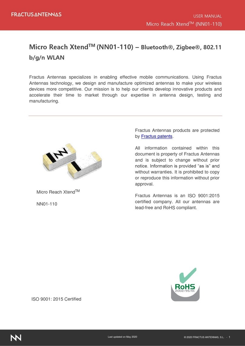
Fractus Antennas TVNow FR01-B1-S-0-047 User manual

Fractus Antennas
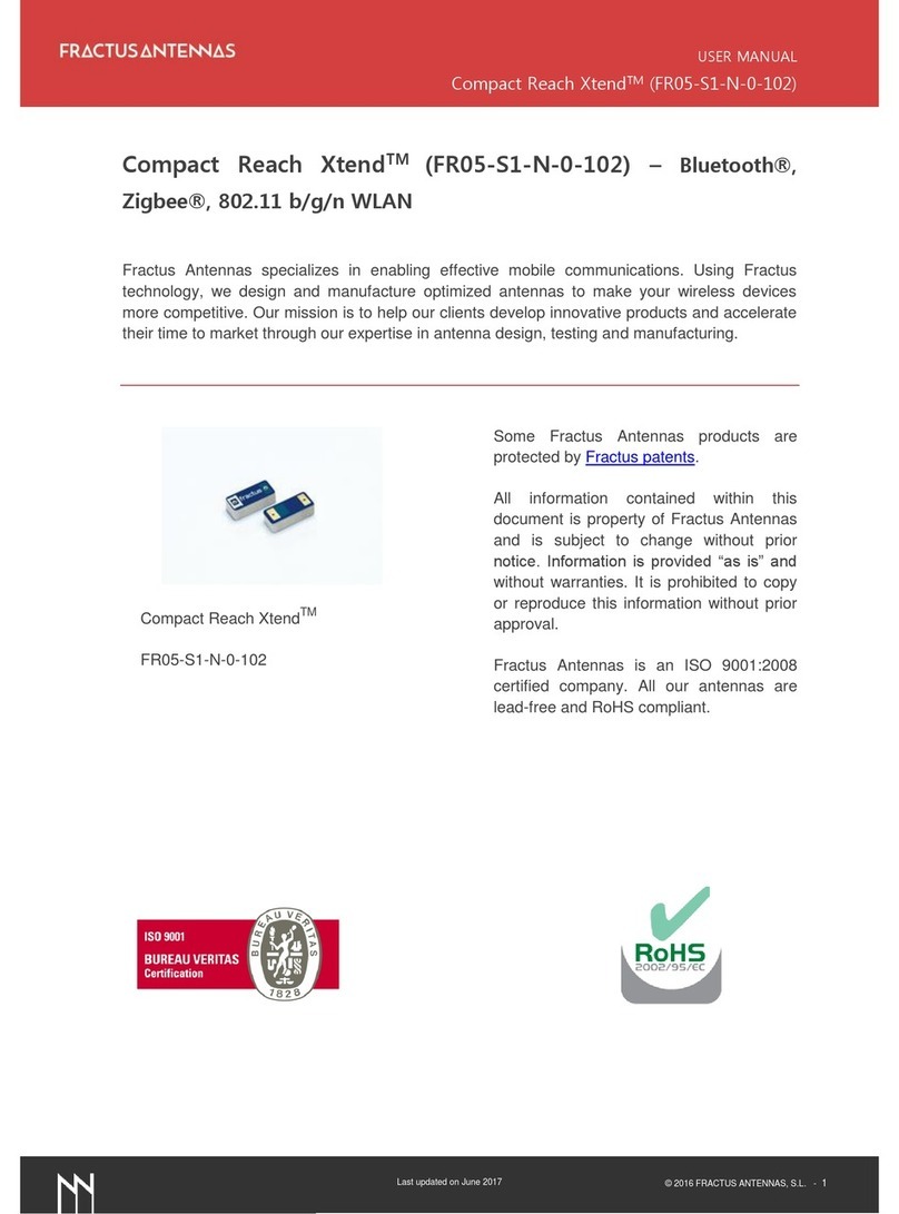
Fractus Antennas Compact Reach Xtend FR05-S1-N-0-102 User manual

Fractus Antennas
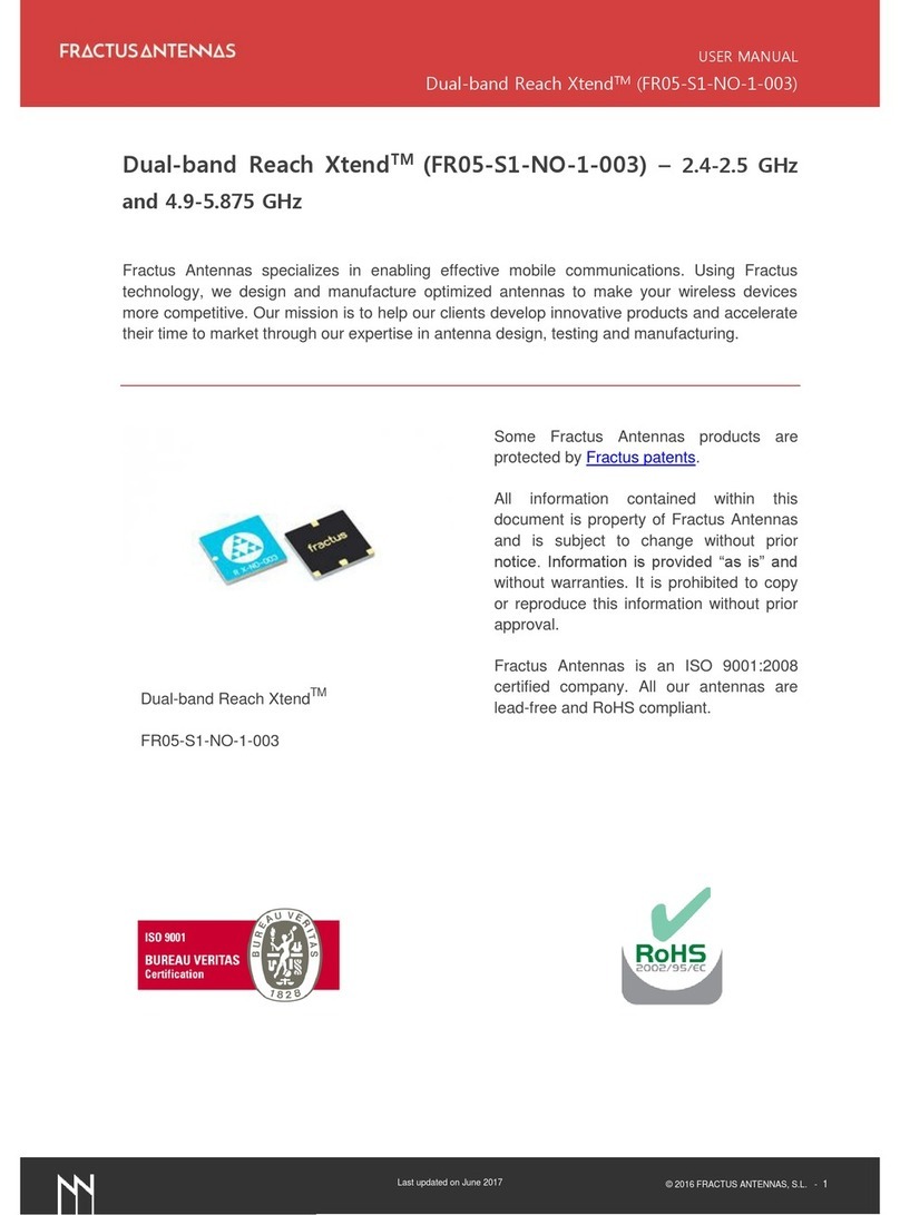
Fractus Antennas Micro Reach Xtend NN01-110 User manual

Fractus Antennas
Fractus Antennas ALL mXTENDTM FR01-S4-220 User manual
Fractus Antennas
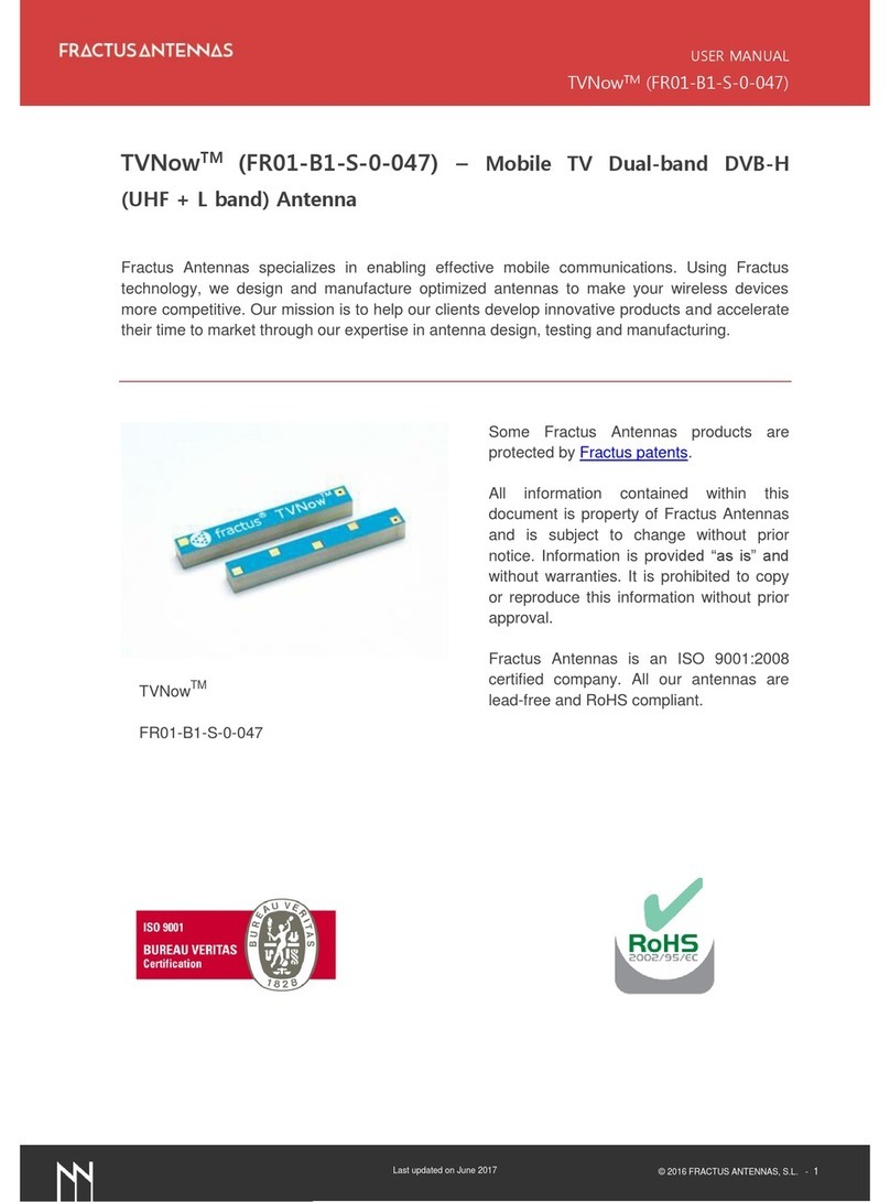
Fractus Antennas FR05-S1-NO-1-003 User manual