Vislink AFD120 Ku User manual

TECHNICAL OPERATION HANDBOOK
For
The Document is supplied on the express terms that it is to be
treated as confidential and that it may not be copied, used or
disclosed to others for any purpose except as authorised by
Vislink.
ADVENT COMMUNICATIONS
Vislink House
27 Maylands Avenue
Hemel Hempstead
Hertfordshire
HP2 7DE
England
Telephone: National 01442 431 300
Fax: 01442 431 301
24 Hour Support +44 (0)1442 431 410
Advent Communications is a brand name of Vislink International
ADVENT FLYDRIVE 120-150 ANTENNA
Document No. 209293 Rev. A

VISLINK
Flydrive 120-150 Antenna
This page left intentionally blank

VISLINK
Flydrive 120-150 Antenna i
CONTENTS
AMENDMENT RECORD SHEET 1
EMC DECLARATION 2
WARNINGS AND HAZARDS 3
ADDITIONAL SAFETY INFORMATION 4
STOWAGE WARNING 4
1.ANTENNA 5
1.1INTRODUCTION 5
2.SPECIFICATION 6
2.1RF 6
2.2DRIVE CONTROL UNIT 7
2.3MECHANICAL 8
2.4ENVIROMENTAL SPECIFICATION 9
3.OPERATING PROCEDURE 10
3.1ANTENNA ASSEMBLY – FLYAWAY CONFIGURATION 10
3.2ANTENNA ASSEMBLY – ROOF RACK MOUNT CONFIGURATION 12
3.3MANUAL OPERATION 13
3.4ANTENNA STOW CONFIGURATIONS 14
3.5OFFSET SATELLITE ADJUSTMENT 18
3.6DRIVE CONTROL UNIT 18
4.FLYDRIVE MAINTENANCE 19
4.1DISH 19
4.2AZIMUTH WORM GEAR 19
4.3POLARISATION DRIVE 19
4.4CABLES 19
4.5FEEDHORN WINDOW 19
4.6FLEXIBLE WAVEGUIDE 19
4.7ALL SCREWS/BOLTS 20
4.8RADIATION CHECK 20
5.ASSEMBLY IMAGES 21
6.WARRANTY 32
6.1WARRANTY INFORMATION 32
6.2CLAIM FOR DAMAGE IN SHIPMENT 32
6.3FIELD SERVICE 32
6.4SHIPMENT OF REPAIR PARTS TO FIELD 32
6.5RETURN PROCEDURES 32
6.6TRANSPORTATION AND PACKAGING 33
6.7AUTHORISATION FOR EVALUATION 33
7.FIGURES 34
FIGURE 1 – FLYDRIVE 120 CONFIGURATION – 402693 34
FIGURE 2 – FLYDRIVE 120 ROOF RACK MOUNT CONFIGURATION – 402692 34
FIGURE 3 – FLYDRIVE 120 PETAL CASE IN SUB 32 KG CONFIGURATIONS – 402690 35
FIGURE 4 – FLYDRIVE 150 FLYAWAY CONFIGURATION - 403080 36
FIGURE 5 – FLYDRIVE 150 ROOF RACK MOUNT CONFIGURATION - 403080 36
FIGURE 6 – FLYDRIVE 150 PETAL CASE IN SUB 32 KG CONFIGURATIONS 402691 37
FIGURE 7 – FLYDRIVE 150 ANTENNA STOWED - 403080 37
FIGURE 8 – SATELLITE GEOMETRY 38

VISLINK
Flydrive 120-150 Antenna ii
This page left intentionally blank

VISLINK
Flydrive 120-150 Antenna 1
AMENDMENT RECORD SHEET
ISS DATE ECR DESCRIPTION OF CHANGE AUTHOR
1 02/2007 N/A New N/A
2 03/2007 N/A Add assembly images. N/A
3 07/2007 N/A Add Flydrive 150 details. N/A
4 08/2008 N/A Add 150 petal assembly order. N/A
5 09/2008 N/A Revised elevation limit. N/A
6 07/2009 N/A Add DC brake input details, change first aid
notes. JM
7 09/2009 N/A Page 41 added. JM
8 25/11/2013 N/A Updated SC
A 16.04.14 N/A Documents RD000431 & 209349
incorporated, case content photos added FGL

VISLINK
Flydrive 120-150 Antenna 2
EMC DECLARATION
VISLINK
Flydrive 120-150 Antenna 3
WARNINGS AND HAZARDS
FAILURE TO OPERATE AND USE THE EQUIPMENT OTHER THAN INSTRUCTED IN
THE MANUAL MAY RESULT IN ELECTRIC SHOCK.
HAZARDOUS WARNING LABELS
NON-IONISING RADIATION
CAUTION – HEAVY ITEMS
CAUTION – MOVING PARTS
TEST/ALIGNMENT OF UNITS FITTED WITH AC/DC POWER SUPPLY
UWARNINGUHazardous voltages are present with lid removed
Diagnostic work on AC powered units or PCBs must be carried out in a test area designated
and equipped for live testing. If units have recently been in operation, time must be allowed
for the discharge of capacitors before handling the unit.
Hazardous AC voltages present
Possible source of radiation hazard, normally
located at waveguide connections, waveguide
joints and antennas.
During operation of the antenna
there will be moving parts; do not
touch whilst in motion
Some items of equipment may weigh
in excess of 25kg, do not attempt to
move or lift without assistance

VISLINK
Flydrive 120-150 Antenna 4
ADDITIONAL SAFETY INFORMATION
Most of the microwave energy
is contained within this beam
Close Up View
Far View
The European Standard that defines power levels is ETS300327.
The microwave power density limit is 10w/m sq.
For a 125w amplifier and 1.2m antenna, the shaded area represents power levels above the
limit. Outside of this area, the power level is below the limit.
This example shows the beam at 21 deg elevation.
The distance R (m) is approximately
R = antilog (eirp/20 - 1.05) where eirp is dBw.
STOWAGE WARNING
If the Flydrive antenna is fitted to a vehicle, ensure that it is stowed when the vehicle is in
motion. The antenna has not been designed to be deployed in this condition and the
resulting forces may exceed the design criteria.
Care should be taken that nothing obstructs the antenna when it is moving as injury or
damage to the antenna or its surroundings may result.

VISLINK
Flydrive 120-150 Antenna 5
1. ANTENNA
1.1 INTRODUCTION
The Flydrive Motorised Antenna System is a highly compact satellite earth terminal, capable
of operating with most of the geostationary C, X, Ku, DBS and Ka band satellites, which are
currently in orbit or are planned.
Its function is to transmit TV programming and communications and to be capable of
monitoring its own transmissions from many sites around the world.
The system has been designed to be used as a flyaway antenna or is able to be fitted to a
standard vehicle roof rack without any modifications to either the antenna or vehicle.
The antenna may be packed in two configurations to allow either quick deployment or case
weights to be under 32kg to comply with the IATA weight restrictions for air travel.
The Antenna Control Unit allows the operator to deploy or stow the antenna with minimum
effort from within the operator’s environment.
The elevation and azimuth backup handle is stowed within the main antenna cases.

VISLINK
Flydrive 120-150 Antenna 6
2. SPECIFICATION
2.1 RF
Type Segmented circular
Diameter 1.2m or 1.5m
Configuration Offset
Mount Elevation over Azimuth
Frequency
Tx C-Band 5.85-6.650 or 6.725-7.025 GHz
X-Band 7.9-8.4 GHz
Ku-Band 13.75-14.50 GHz or 12.75-13.25 GHz
DBS-Band 17.3-18.1 GHz (optional 18.4GHz)
Ka-Band 27.5-30.0 GHz or 30.0 to 31.0 GHz
Rx C-Band 3.7-4.2 or 4.5-4.8 GHz
X-Band 7.25-7.75 GHz
Ku-Band 10.70-12.75 GHz
DBS-Band 10.70-12.75 GHz
Ka-Band 18.0-22.0 GHz
1.2m 1.5m
Gain dBi Tx C-Band
Tx X-Band
Tx Ku-Band
Tx DBS-Band
Tx Ka-Band
-
-
Defined at
the OMT
flange
Rx C-Band
Rx X-Band
Rx Ku-Band
Rx DBS-Band
Rx Ka-Band
WG loss C-Band 0.35 dB
Ku-Band 0.65 dB
Off-axis gain Tx 29-25 log100/D < 0 < 20°.
-3.5 20 < 0 < 26.4°.
32-25 log26.4 < 0 < 48°.
Rx
32-25 log100/D < 0 < 48°.
Polarisation Linear-orthogonal (C, Ku, DBS and Ka)
Circular (C, X and Ka)
Cross polar isolation -35 dB rel co-polar gain within 0.2deg
(Ku and DBS)

VISLINK
Flydrive 120-150 Antenna 7
VSWR
Tx Rx
C 1.2:1 1.3:1
X 1.4:1 1.35:1
Ku 1.2:1 1.3:1
DBS 1.3:1 1.5:1
Ka 1.3:1 1.3:1
Port/Port isolation
C TX/RX: 40 dB (110dB incl filter)
RX/TX 30 dB
X TX/RX 20 dB (100dB incl filter)
Rx/Tx 20 dB
Ku TX/RX 40 dB (110dB incl filter)
Rx/Tx 30 dB
DBS TX/RX 40 dB (110dB incl filter)
Rx/Tx 30 dB
Waveguide Flanges Advent Q/R Flange and:
C-Band CPR137
X-Band UBR84/CPR112
Ku-Band UBR120
DBS-Band UBR140
Ka UBR320/UBR220
Feed 2 port (3,4 port optional)
Power (RF) 500w cw
2.2 DRIVE CONTROL UNIT
Antenna Limits
Polarisation ± 95°
Azimuth -200° to +200°
Elevation 6° to 92°
Display
Resolution 0.1°
Power
Power Connector 3 Pin IEC plug with dual fusing
AC Supply 90-264V AC. (47-63Hz)
Consumption < 100VA
VISLINK
Flydrive 120-150 Antenna 8
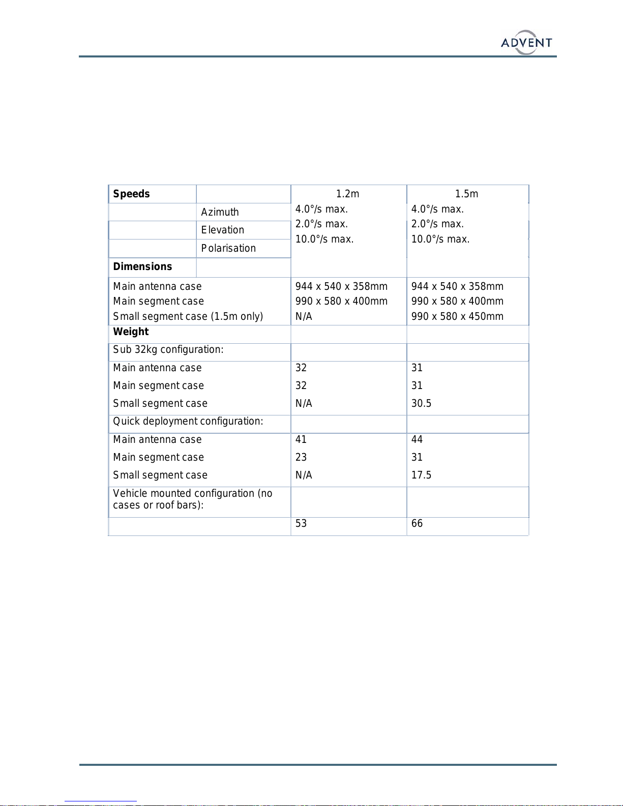
2.3 MECHANICAL
Azimuth adjustment ± 200°
Elevation adjustment 6° to 92°
Pol. Adjustment ± 95°
Motorisation Azimuth
Elevation
Polarisation
Speeds 1.2m
4.0°/s max.
2.0°/s max.
10.0°/s max.
1.5m
4.0°/s max.
2.0°/s max.
10.0°/s max.
Azimuth
Elevation
Polarisation
Dimensions
Main antenna case
Main segment case
Small segment case (1.5m only)
944 x 540 x 358mm
990 x 580 x 400mm
N/A
944 x 540 x 358mm
990 x 580 x 400mm
990 x 580 x 450mm
Weight
Sub 32kg configuration:
Main antenna case
Main segment case
Small segment case
32
32
N/A
31
31
30.5
Quick deployment configuration:
Main antenna case
Main segment case
Small segment case
41
23
N/A
44
31
17.5
Vehicle mounted configuration (no
cases or roof bars):
53 66
VISLINK
Flydrive 120-150 Antenna 9
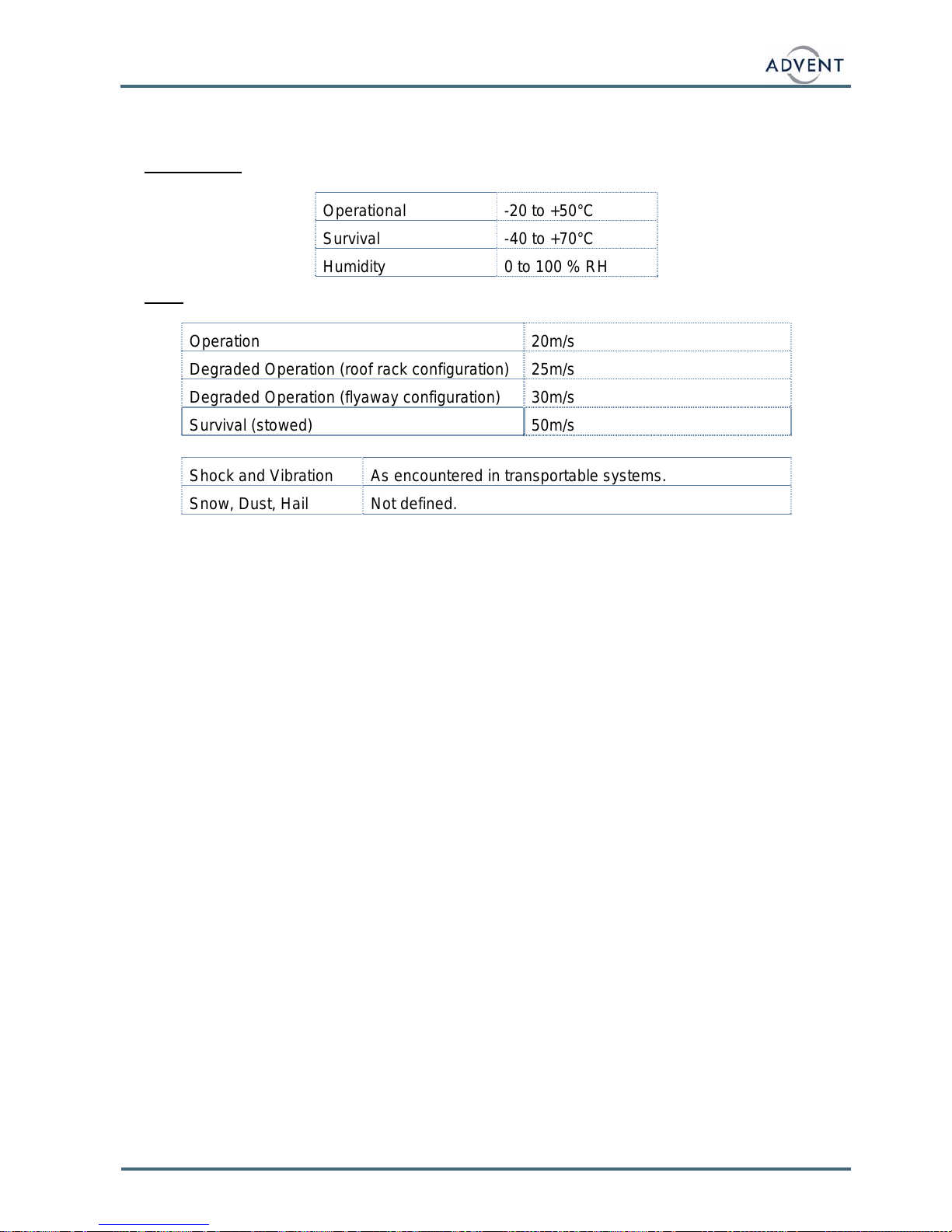
2.4 ENVIROMENTAL SPECIFICATION
The system will be used outdoors, exposed to the prevailing ambient conditions.
Temperature
Operational -20 to +50°C
Survival -40 to +70°C
Humidity 0 to 100 % RH
Wind
Operation 20m/s
Degraded Operation (roof rack configuration) 25m/s
Degraded Operation (flyaway configuration) 30m/s
Survival (stowed) 50m/s
Shock and Vibration As encountered in transportable systems.
Snow, Dust, Hail Not defined.

VISLINK
Flydrive 120-150 Antenna 10
3. OPERATING PROCEDURE
See Section 5 for the relevant assembly images.
3.1 ANTENNA ASSEMBLY – FLYAWAY CONFIGURATION
Open up the main antenna case.
If the antenna was stowed in its sub 32kg configuration (see section 3.4), remove the
four elevation arm fasteners from the main azimuth base. If the antenna was stowed in
its quick deployment configuration then go to the 6th bullet point. See section 3.4 for the
different case configurations.
Remove the reflector centre section from the segment case and place on top of the
azimuth base, in front of the azimuth cable interface. Connect up the cables from the
elevation axis to the azimuth cable interface panel (elevation motor cable, inclinometer
cable, elevation sensor cable, feedarm limit switch cable and the compass cable - when
supplied).
Place the reflector centre section onto the turntable using the dowels to aid location.
Care should be taken to make sure that the lower feedarm is released when locating the
reflector centre section. If necessary the lower feedarm can be released by gently
pushing up the two retaining clips on the side of the feedarm and lifting the feedarm.
Also ensure that the elevation sensor wire does not get trapped under the pivot leg.
Replace the four elevation axis bolts.
Place the main antenna case lid on the ground and place the main antenna base back
on top of the case.
Fasten the latches that secure the base onto its case.
Fit the front and rear antenna stabilising legs and adjust so that the antenna base is
level.
Connect the power and control cables to the main base cable interface panel.
Repetitively select the deploy command from the front panel of the ACU. On each deploy
command the elevation will raise up a few degrees then stop. Continue the deploy
commands until the elevation axis continues moving up at a higher rate once the
elevation stow sensor has been cleared.
Connect the upper feedarm to the lower feedarm.
Fasten the cartridge to the upper feedarm.
Fit the flex twist waveguide to the lower feedarm and cartridge RF ‘in’ port using the
quick release flange.
Place the flex twist waveguide over the waveguide support half way up the upper
feedarm.
Connect the polarisation motor control cable to the azimuth cable interface panel.
Connect the L band cable between the LNB and azimuth cable interface panel. Care
should be taken to pass both cables over the feedarm as shown. Use the Velcro straps
to hold the polarisation motor cable and L band cable to the flex twist waveguide and
other cables.
On the Flydrive 120, fit the three outer reflector segments, fitting the two side segments
first and the top segment last. On the Flydrive 150, fit the top centre section first, then
the lower outer sections, then the upper outer sections.

VISLINK
Flydrive 120-150 Antenna 11
Ensure that the polarisation drive is in its stowed position by looking at the polarisation
scale. If it is not in it’s stow position then rotate the feed to it’s stow position by pushing
the LNB to move the back section of the feedhorn. Select the stow command from the
front panel of the ACU. Once stowed, re-deploy the antenna and confirm that the
polarisation axis deploys and calibrates successfully.
The segment case may be used as a platform for any HPA or control electronics that are
being used with the system.
To stow the antenna remove the reflector segments, feedarm and cartridge, and select
the stow command from the front panel of the ACU. The antenna will stow with the
elevation axis stopping in its high stow position. If the elevation axis is required to be put
into its lower elevation stow position, to fit the unit in its flight case, selecting the stow
command from the front panel of the ACU will command the Flydrive to move to its lower
elevation stow position.
If the antenna is to be stowed in its sub 32kg configuration also removes the reflector
centre section. The two case configurations are shown in section 3.4.

VISLINK
Flydrive 120-150 Antenna 12
3.2 ANTENNA ASSEMBLY – ROOF RACK MOUNT CONFIGURATION
Warning:
The antenna should be fitted with the reflector facing the rear of the vehicle to
reduce wind loads during transit and protect the feedhorn assembly.
All fasteners and fitting that hold the antenna onto the vehicle and hold parts of
the antenna together should be checked before every journey. If any fasteners
are damaged then the vehicle should not be driven with the antenna fitted to
the roof rack. Try to push and pull the antenna out of its locked position. If any
movement is seen then the roof rack fittings should be tightened.
All checks associated with the roof rack should also be carried out.
If you are in any doubt that the antenna and all its parts are not securely held in
place then do not drive the vehicle with the antenna fitted to the roof rack.
The load capacity for the roof rack and vehicle should not be exceeded and
Advent recommends the use of higher load capacity roof rack components. For
example, a set of Thule 755 feet have a rated maximum load capacity of 100kg
compared to 75kg for standard feet. The increased load capacity will improve
the system stiffness and so reduce any RF losses.
Fit the roof rack (not supplied) to the vehicle if not already present. The roof rack bars
and feet and vehicle should be capable of supporting the antenna weight including any
amplifier and/or RF options. If there is an option for a high strength/stiffness rack, then
this should be fitted (for example, Thule supply reinforced load bars and higher load
capacity feet).
As with the flyaway configuration, fit the reflector centre section if the antenna was
stowed in its sub 32kg configuration.
Fit the antenna base front roof rack rails onto the main antenna base. The rear roof rack
rails are permanently fitted to the antenna base.
Slide the roof rack feet onto the rails and fit the end caps. Ensure that the end caps are
pushed fully into the roof bars. Use the end caps with the short extensions on the rear
bars and the end caps with the long extensions on the front bars.
Open up the roof bar feet sufficiently so that they may be slid over the roof rails on the
vehicle.
Lift the antenna base onto the roof rack bars and slide the roof rack feet so that they are
positioned at the correct width to fit the roof rack. Engage the roof rack feet over the roof
rack bars and tighten the roof rack feet and push the end cap fully in.
Partially deploy the antenna as with the flyaway configuration. Fit the lower and upper
feedarm and connect all cables and flex/twist waveguide. Fit the outer reflector
segments.
Note: - Consideration should be given to the vehicle suspension movement during
operation. Ideally jacks should be used to lock the vehicle suspension during operation
and may be necessary for operation at the higher end of the specified operational wind
speeds. If the vehicle does not have its suspension locked off and the wind loads do not
affect the antenna performance, movement due to people entering or leaving the vehicle
can be significant and may result in a temporary reduction in RF performance. Steps
should be taken to reduce the chance of this happening.
If the optional HPA mounting kit is supplied, fit the mounting brackets onto the HPA and

VISLINK
Flydrive 120-150 Antenna 13
lift the amplifier onto the roof rack next to the antenna base.
Fasten the inner HPA mounting bracket onto the main antenna base.
Fasten the outer clamp around the roof bar.
Fit the cross site waveguide between the HPA and feedarm base waveguide interface.
Care should be taken in operation that the flex/twist waveguide can run freely between
the amplifier and antenna. An antenna movement of between +90 and –180 degrees in
azimuth should not cause problems, but it may be necessary to either point the antenna
without the cross site waveguide fitted or move the vehicle for full 360 degrees azimuth
movement.
Select the deploy command from the front panel of the ACU. The Flydrive will deploy
automatically, calibrating the elevation, azimuth and polarisation axis on each deploy
sequence. Select the stow command from the front panel of the ACU. The Flydrive will
stow automatically.
To remove the roof rack feet from the antenna, remove the end cap completely from the
end cap housing and push the inner release latch in and pull the end cap housing out of
the roof bar.
3.3 MANUAL OPERATION
The antenna may be moved manually if there is a problem with the control circuit.
The azimuth axis is moved by inserting the manual drive a handle into the azimuth adjust
slot in the side of the antenna base and turning.
Apply power to the antenna using the main power cable. The elevation axis is moved by
releasing the brake using the switch on the main antenna cable interface panel and
inserting the manual drive handle into the elevation adjust slot in the side of the antenna
base and turning.
The polarisation axis is moved by rotating the rear section of the feedhorn.
If AC power is not available a 12V DC input may be used to release the brakes. Insert
the supplied brake override DC input cable, apply a 12V DC battery and use the brake
release switch as with the AC input. The cable pin outs are shown below.

VISLINK
Flydrive 120-150 Antenna 14
3.4 ANTENNA STOW CONFIGURATIONS
The antenna may be stowed in its cases in one of two configurations. The first configuration
keeps the cases below the 32kg IATA requirement for air travel, but requires more setup
time. The second quick deployment configuration allows the antenna to be assembled in less
time but results in one case that exceeds 32kg.
Flydrive 120 sub 32 kg configuration
Main antenna case contents:
Antenna base
Antenna stabilising legs and levelling feet
Upper feedarm
Reflector left section
Reflector right section
Segment case contents:
Reflector centre section (with lower feedarm and elevation axis attached)
Reflector top section
Accessory case contents:
Feedhorn cartridge
Roof rack runners and feet (when supplied)
Flydrive 120 quick deployment configuration
Main antenna case contents:
Antenna base
Reflector centre section (with lower feedarm and elevation axis attached)
Segment case contents:
Antenna stabilising legs and levelling feet
Upper feedarm
Feedhorn cartridge
Roof rack runners and feet (when supplied)
Reflector top section
Reflector left section
Reflector right section

VISLINK
Flydrive 120-150 Antenna 15
MAIN ANTENNA CASE FLYDRIVE 120
QUICK DEPLOYMENT
SUB 32Kg
SEGMENT CASE FLYDRIVE 120
QUICK DEPLOYMENT
SUB 32Kg
ACCESSORY CASE

VISLINK
Flydrive 120-150 Antenna 16
Flydrive 150 sub 32kg configuration
Main antenna case contents:
Antenna base
Upper feedarm
Feedhorn cartridge
Segment case contents:
Lower:- Reflector centre top section
Reflector left top section
Reflector right top section
Upper:- Reflector left bottom section
Reflector right bottom section
Feedarm flex/twist waveguide (1.3m)
Front roof bars
Thule feet with adjusters x 4
Antenna levelling feet and tool kit
Small segment case contents:
Lower:- Reflector centre section (with lower feedarm and elevation axis attached)
Antenna stabilising legs
Upper:- Cross site waveguide (1.1m)
AC power cable
Rx L band cable
Flydrive 150 quick deployment configuration
Main antenna case contents:
Antenna base
Reflector centre section (with lower feedarm and elevation axis attached)
Segment case contents (this is the same as the quick deploy configuration):
Lower:- Reflector centre top section
Reflector left top section
Reflector right top section
Upper:- Reflector left bottom section
Reflector right bottom section
Feedarm flex/twist waveguide (1.3m)
Front roof bars
Thule feet with adjusters x 4
Antenna levelling feet and tool kit
Small segment case contents:
Lower:- Antenna stabilising legs
This manual suits for next models
6
Table of contents
Other Vislink Antenna manuals


Popular Antenna manuals by other brands

True
True Jiuzhou JZDTS5418 How to set up

Taco
Taco Y102B-150V Instruction booklet

M2 Antenna Systems
M2 Antenna Systems 7-10-30LP8 Assembly instructions

Hirschmann
Hirschmann GLONASS 9 M Mounting instructions

Applied Satellite Engineering
Applied Satellite Engineering ASE AA511 quick start guide

Mopar
Mopar 82210940AD manual


