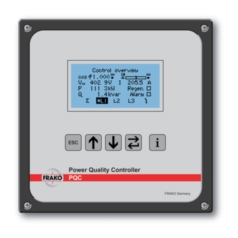
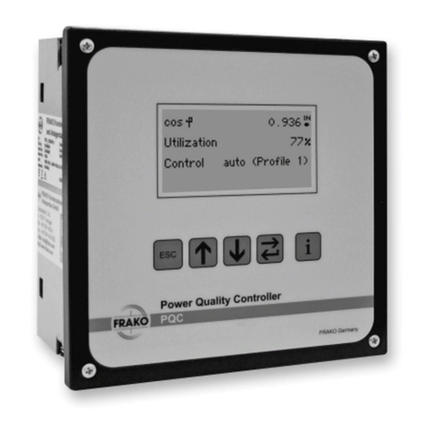
frako PQC User manual

FRAKO Kondensatoren- und Anlagenbau GmbH
www.frako.com
OPERATING MANUAL
The controller that maximizes reliability
and monitors power quality
PQC
Power Quality Controller

2 |
Power Quality Controller – PQC | Operating Manual | FRAKO
Contents
1 About this manual �������������������������������������������������������������������������������������4
1.1 Objective . . . . . . . . . . . . . . . . . . . . . . . . . . . . . . . . . . . . . . . . . . . . . . . . . . . . . 4
1.2 Safekeeping . . . . . . . . . . . . . . . . . . . . . . . . . . . . . . . . . . . . . . . . . . . . . . . . . . 4
1.3 Symbols used in this manual. . . . . . . . . . . . . . . . . . . . . . . . . . . . . . . . . . . . . . 4
1.4 Reference documents . . . . . . . . . . . . . . . . . . . . . . . . . . . . . . . . . . . . . . . . . . . 5
2 Safety ���������������������������������������������������������������������������������������������������������6
2.1 Intended use . . . . . . . . . . . . . . . . . . . . . . . . . . . . . . . . . . . . . . . . . . . . . . . . . . 6
2.2 Instrument-specific dangers . . . . . . . . . . . . . . . . . . . . . . . . . . . . . . . . . . . . . . 6
2.3 Management information. . . . . . . . . . . . . . . . . . . . . . . . . . . . . . . . . . . . . . . . . 7
2.4 Disclaimer . . . . . . . . . . . . . . . . . . . . . . . . . . . . . . . . . . . . . . . . . . . . . . . . . . . . 7
2.5 Relevant standards . . . . . . . . . . . . . . . . . . . . . . . . . . . . . . . . . . . . . . . . . . . . . 8
2.6 Repair . . . . . . . . . . . . . . . . . . . . . . . . . . . . . . . . . . . . . . . . . . . . . . . . . . . . . . . 8
3 Technical data �������������������������������������������������������������������������������������������9
4 Instrument description ���������������������������������������������������������������������������15
4.1 Function . . . . . . . . . . . . . . . . . . . . . . . . . . . . . . . . . . . . . . . . . . . . . . . . . . . . 15
4.2 Instrument versions . . . . . . . . . . . . . . . . . . . . . . . . . . . . . . . . . . . . . . . . . . . . 16
4.3 User interface . . . . . . . . . . . . . . . . . . . . . . . . . . . . . . . . . . . . . . . . . . . . . . . . 16
4.4 Password protection . . . . . . . . . . . . . . . . . . . . . . . . . . . . . . . . . . . . . . . . . . . 17
5 Installation �����������������������������������������������������������������������������������������������18
5.1 Mounting at the desired location . . . . . . . . . . . . . . . . . . . . . . . . . . . . . . . . . . 18
5.1.1 Preparing for installation. . . . . . . . . . . . . . . . . . . . . . . . . . . . . . . . . . . 18
5.1.2 Scope of supply. . . . . . . . . . . . . . . . . . . . . . . . . . . . . . . . . . . . . . . . . 18
5.1.3 Suitable location . . . . . . . . . . . . . . . . . . . . . . . . . . . . . . . . . . . . . . . . 18
5.1.4 Mounting the instrument . . . . . . . . . . . . . . . . . . . . . . . . . . . . . . . . . . 19
5.2 Electrical installation. . . . . . . . . . . . . . . . . . . . . . . . . . . . . . . . . . . . . . . . . . . . 20
5.2.1 Electrical installation procedure . . . . . . . . . . . . . . . . . . . . . . . . . . . . . 20
5.2.2 Completing the electrical installation . . . . . . . . . . . . . . . . . . . . . . . . . 21
5.2.3 Specifications for the electrical connections . . . . . . . . . . . . . . . . . . . 22
5.2.4 Earth connection . . . . . . . . . . . . . . . . . . . . . . . . . . . . . . . . . . . . . . . . 22
5.2.5 Power supply. . . . . . . . . . . . . . . . . . . . . . . . . . . . . . . . . . . . . . . . . . . 22
5.2.6 Voltage measurement . . . . . . . . . . . . . . . . . . . . . . . . . . . . . . . . . . . . 23
5.2.7 Current measurement . . . . . . . . . . . . . . . . . . . . . . . . . . . . . . . . . . . . 24
5.2.8 Output relays (control outputs). . . . . . . . . . . . . . . . . . . . . . . . . . . . . . 25
5.2.9 Alarm function . . . . . . . . . . . . . . . . . . . . . . . . . . . . . . . . . . . . . . . . . . 25
5.2.10 Connection diagrams for all PQC types. . . . . . . . . . . . . . . . . . . . . . . 25
5.3 Commissioning (initial start-up) . . . . . . . . . . . . . . . . . . . . . . . . . . . . . . . . . . . 30
5.3.1 Preparations for start-up . . . . . . . . . . . . . . . . . . . . . . . . . . . . . . . . . . 30
5.3.2 PQC initial start-up. . . . . . . . . . . . . . . . . . . . . . . . . . . . . . . . . . . . . . . 30
5.3.3 Automatic connection and stage identification. . . . . . . . . . . . . . . . . . 32
5.3.4 Manual connection and stage identification . . . . . . . . . . . . . . . . . . . . 33

| 3
FRAKO | Operating Manual | Power Quality Controller – PQC
6 Description of the menu �������������������������������������������������������������������������37
6.1 Main menu . . . . . . . . . . . . . . . . . . . . . . . . . . . . . . . . . . . . . . . . . . . . . . . . . . 37
6.2 Display. . . . . . . . . . . . . . . . . . . . . . . . . . . . . . . . . . . . . . . . . . . . . . . . . . . . . . 38
6.2.1 PFC . . . . . . . . . . . . . . . . . . . . . . . . . . . . . . . . . . . . . . . . . . . . . . . . . . 39
6.2.2 System & PQ. . . . . . . . . . . . . . . . . . . . . . . . . . . . . . . . . . . . . . . . . . . 41
6.2.3 Service. . . . . . . . . . . . . . . . . . . . . . . . . . . . . . . . . . . . . . . . . . . . . . . . 43
6.2.4 Alarms & notifications . . . . . . . . . . . . . . . . . . . . . . . . . . . . . . . . . . . . 45
6.3 Configuration. . . . . . . . . . . . . . . . . . . . . . . . . . . . . . . . . . . . . . . . . . . . . . . . . 47
6.3.1 System parameters . . . . . . . . . . . . . . . . . . . . . . . . . . . . . . . . . . . . . . 48
6.3.2 PFC Equip. parameters . . . . . . . . . . . . . . . . . . . . . . . . . . . . . . . . . . . 48
6.3.3 Control parameters . . . . . . . . . . . . . . . . . . . . . . . . . . . . . . . . . . . . . . 48
6.3.4 Alarms . . . . . . . . . . . . . . . . . . . . . . . . . . . . . . . . . . . . . . . . . . . . . . . . 54
6.3.5 Communication (optional) . . . . . . . . . . . . . . . . . . . . . . . . . . . . . . . . . 60
6.3.6 Temperature I/O (optional) . . . . . . . . . . . . . . . . . . . . . . . . . . . . . . . . . 63
6.3.7 Service. . . . . . . . . . . . . . . . . . . . . . . . . . . . . . . . . . . . . . . . . . . . . . . . 65
6.4 About PQC . . . . . . . . . . . . . . . . . . . . . . . . . . . . . . . . . . . . . . . . . . . . . . . . . . 67
6.5 Factory settings. . . . . . . . . . . . . . . . . . . . . . . . . . . . . . . . . . . . . . . . . . . . . . . 67
6.6 Service interface . . . . . . . . . . . . . . . . . . . . . . . . . . . . . . . . . . . . . . . . . . . . . . 72
7 General operation �����������������������������������������������������������������������������������72
8 Cleaning and maintenance���������������������������������������������������������������������73
8.1 Safety during cleaning and maintenance. . . . . . . . . . . . . . . . . . . . . . . . . . . . 73
8.2 Cleaning . . . . . . . . . . . . . . . . . . . . . . . . . . . . . . . . . . . . . . . . . . . . . . . . . . . . 73
8.3 Maintenance . . . . . . . . . . . . . . . . . . . . . . . . . . . . . . . . . . . . . . . . . . . . . . . . . 73
9 Troubleshooting���������������������������������������������������������������������������������������74
10 Decommissioning and removal, storage and disposal �����������������������78
10.1 Decommissioning the PQC . . . . . . . . . . . . . . . . . . . . . . . . . . . . . . . . . . . . . . 78
10.2 PQC removal. . . . . . . . . . . . . . . . . . . . . . . . . . . . . . . . . . . . . . . . . . . . . . . . . 79
10.3 Storage . . . . . . . . . . . . . . . . . . . . . . . . . . . . . . . . . . . . . . . . . . . . . . . . . . . . . 79
10.4 Disposal . . . . . . . . . . . . . . . . . . . . . . . . . . . . . . . . . . . . . . . . . . . . . . . . . . . . 79

4 | About this manual
Power Quality Controller – PQC | Operating Manual | FRAKO
1 About this manual
The PQC Power Quality Controller is an instrument for controlling the power factor and
other power quality parameters. Throughout this manual, it will be referred to simply
as the PQC.
The current version of this manual can be accessed at our website: www.frako.com.
1.1 Objective
This operating manual has been prepared for persons who install, connect, commis-
sion and operate the PQC. The manual must be read through carefully and completely
before any work on or with the instrument is carried out. All actions taken must be in
accordance with this manual.
1.2 Safekeeping
This operating manual contains important instructions for operating the PQC safely,
correctly and cost-effectively. It is to be considered part of the instrument itself and
must be held in a secure place where it can be referred to at all times.
1.3 Symbols used in this manual
Special instructions in this operating manual are marked by symbols and separated
from the other text by lines.
Warning signs
In order to avoid accidents, death or injury and damage to assets, these instructions
must always be followed. The warning signs consist of the appropriate key word –
DANGER, WARNING, CAUTION or ATTENTION – plus a yellow symbol on the left-
hand side, as shown below:
WARNING!
Type of danger!
Description of the danger and possible consequences
–Actions to avoid the danger

About this manual | 5
FRAKO | Operating Manual | Power Quality Controller – PQC
The symbols and key words classify the extent of the danger:
Symbol Key word Meaning
DANGER This key word indicates a hazard with a high level of risk that if
not avoided can result in death or serious injury.
WARNING This key word indicates a hazard with an intermediate level of risk
that if not avoided can result in death or serious injury.
CAUTION This key word indicates a hazard with a low level of risk that if not
avoided can result in slight or moderate injury.
ATTENTION Damage to property could occur if this sign is not heeded.
Notes
Notes supplement the general text with additional information on the correct func-
tioning and fault-free operation of the PQC. They are marked with the white-on-blue
symbol on the left-hand side, as shown below:
Note
Example of a note
1.4 Reference documents
For further information on the PQC please refer to the following documents:
– “PQC Application Note”
– “Modbus Specification”
– “REST Application Note”

6 | Safety
Power Quality Controller – PQC | Operating Manual | FRAKO
2 Safety
2.1 Intended use
Within the scope of the technical data (see Section 3 “Technical data”), the PQC
Power Quality Controller is intended for the control of power factor cosφby switching
reactive power in and out. Any use of the instrument that deviates from its intended
use must be expressly approved by the manufacturer.
2.2 Instrument-specic dangers
The PQC has been manufactured using state-of-the-art technology. Nevertheless, not
all potential dangers can be excluded.
Failure to observe the safety instructions can result in death, serious injury or severe
damage to equipment and other assets.
Danger from electricity
The PQC operates at the supply voltage. Touching live components at the instrument
terminals and connecting cables can cause serious injury or may even be life-threat-
ening.
– Installation, commissioning and decommissioning of the PQC may only be carried
out by appropriately qualified technicians who are also familiar with and under-
stand the contents of this manual.
– When the PQC is being installed or serviced, the instrument and the electrical
system must be isolated from the power supply.
– The isolated electrical system must be locked out and tagged to prevent its being
inadvertently switched on again.
– It must be verified that none of the terminals are live.
– All live components in the vicinity must be covered to prevent inadvertent contact.
– Current transformer circuits must be short-circuited before they are interrupted.
– Only approved installation cables must be used.
– The PQC must only be employed on duties up to the specified maximum power.
Overloading the instrument can result in its destruction, create a fire hazard or
cause an electrical accident. The load ratings for the various connections must
not be exceeded.
– Do not open the PQC.
– When the PQC is in operation, the USB port must not be touched.

Safety | 7
FRAKO | Operating Manual | Power Quality Controller – PQC
Danger from heat
The instrument terminals can become hot during operation.
– After the PQC has been operating, sufficient time must be allowed for the PQC
and its terminals to cool down before work is carried out on the connections.
2.3 Management information
Personnel qualifications
The following qualifications are required for personnel working with the PQC:
– Installing, commissioning, troubleshooting (installation):
electrician
– Operation, troubleshooting (faulty configuration):
persons who have read and understood the operating manual.
– Troubleshooting (instrument faults):
FRAKO Service + Support
User responsibility
In commercial operations in Germany, it is essential to comply with the regulations
of the Social Accident Insurance Institution covering electrical installations. In other
countries, the equivalent local regulations must be followed.
The safety of the system in which the PQC is incorporated is the responsibility of the
persons installing and operating the system.
For safety reasons and to retain conformity with product approval requirements (CE
marking), the user is not permitted to convert or otherwise modify the PQC.
The user must ensure that all operators are familiarized with this operating manual
and follow it at all times.
2.4 Disclaimer
No claims under guarantee shall be valid in the event of damages caused by failure
to observe the instructions in this operating manual. We shall not be held liable for
consequential damages!
Incorrect operation or failure to observe the safety instructions will invalidate all claims
under the guarantee, and no liability is accepted for any injuries to persons or dam-
ages to assets arising therefrom or occasioned thereby!

8 | Safety
Power Quality Controller – PQC | Operating Manual | FRAKO
2.5 Relevant standards
Installation and commissioning of the instrument in industrial plant must be carried out
in strict compliance with the following standards:
– EN 61508-1:2011-02; VDE 0803-1:2011-02
Any other laws, standards, regulations and safety rules (IEC, EN, VDE, etc.) relevant to
this product and the protection of persons and assets must be observed. In Germany,
it is essential to comply with the Equipment Safety Act (GSG) and the regulations of
the German Social Accident Insurance Institutions. In other countries, the equivalent
local regulations must be followed.
2.6 Repair
Should repair work be necessary, the customer or user must contact the manufacturer
of the PQC: FRAKO Kondensatoren und Anlagenbau GmbH, Tscheulinstrasse 21A,
D-79331 Teningen, Germany; www.frako.com.

Technical data | 9
FRAKO | Operating Manual | Power Quality Controller – PQC
3 Technical data
Power supply:
Type xxx240x-xx xxx480x-xx
Supply voltage
85–267 V AC (absolute limits),
frequency 45–65 Hz,
or 100–377 V DC (absolute limits)
85–530 V AC (absolute limits),
frequency 45–65 Hz,
or 100–750 V DC (absolute limits)
Power draw maximum 5 VA
Overcurrent
protection External, maximum 2 A (time delay) specified
Inputs:
Category Single phase 3-phase
Type xxxxxx1-xx xxxxx3-xx
Voltage path
measurement
inputs
80 V AC – maximum 760 V AC (phase–phase, absolute limits), suitable
for 115–690 V AC networks, electrically interconnected via high
resistances, measurement of medium voltages possible using an
x/100 V transformer;
In areas where UL / CSA standards apply (versions PQC xxx480x-xx):
networks with nominal voltages 115–600 V AC;
power failure detection after duration of a half-wave
Current path
measurement
inputs
x/5 A AC or x/1 A AC (transformer secondary current ≥ 15 mA), electri-
cally isolated, power draw maximum 1 VA per transformer connection,
continuous overload rating up to 6 A AC, transient overload maximum
10A AC for 10 seconds
Digital inputs Up to five digital inputs
5–24V DC inputs, alternatively usa-
ble as up to 5 x 24 V DC, 100mA
outputs, electrically interconnected
with each other and the tempera-
ture input
Temperature
inputs
1 x PT-100 or PT-1000 RTD, 4-wire
or 2-wire configuration, automatic
probe type identification;
2 x NTC thermistor type TDK/
Epcos-B57861S0502F040,
FRAKO Article No. 29-20094,
measuring range –50°C to
+200°C, electrically connected with
the digital outputs

10 | Technical data
Power Quality Controller – PQC | Operating Manual | FRAKO
Category Single phase 3-phase
Type xxxxxx1-xx xxxxx3-xx
Type xxxxxx-4x
Prole switching
(T)
S0 pulse as per DIN 43864,
common earth with FRAKO Starkstrombus (Frakobus)
Interfaces:
Type xxxxxx-2x xxxxxx-3x xxxxxx-4x
Modbus RTU
interface
120 Ω terminating
resistor required at the
end of the bus system
Ethernet interface
(Modbus TCP, web
server)
100 Mbit/s
Ethernet standard
100BASE-T
FRAKO
Starkstrombus
(Frakobus)
RS-485, surge
impedance 120 Ω,
for connection to the
FRAKO Energy
Management System
Outputs:
Category 12 output relays 6 output relays 6 output relays
Type 120xxxx-xx 060xxxx-xx 061xxxx-xx
Output relays
(outputs for
switching stages)
NO contact with common pole P;
AC- 14 250 V AC, maximum 3 A
or DC- 13 30 V DC, maximum 3 A,
mechanical service life 2 × 10⁷cycles,
electrical service life AC- 14 at 3 A:
1 × 10⁵cycles,
AC- 14 at 0.5 A: 2 × 10⁶cycles
AC-14 440 V AC,
max. 3 A
or DC-13 125 V DC,
max. 3 A, mechanical
service life
1 × 10⁷cycles, electri-
cal service life AC-14
at 3 A:1 × 10⁵cycles,
AC-14
at 0.5 A: 2 × 10⁶
cycles
Common supply conductor P to the output relays maximum 10 A;
Note: utilization category AC-14/DC-13 as per IEC 60947-5-1; for all
PQC types in areas where UL / CSA standards apply: 3 A 250 V AC
cosφ=1 at 85 °C, 3 A 30 V DC L/R = 0ms at 85 °C

Technical data | 11
FRAKO | Operating Manual | Power Quality Controller – PQC
Category 12 output relays 6 output relays 6 output relays
Type 120xxxx-xx 060xxxx-xx 061xxxx-xx
Alarm contact
Volt-free NO contact, AC-14 250 V AC, max. 3 A or DC-13 30 V DC,
max. 3 A, mechanical service life 2 × 10⁷cycles, electrical service life
AC-14 at 3 A 1.5 × 10⁵cycles, AC-14 at 0.5 A 2 × 10⁶cycles.
Note: utilization category AC-14/DC-13 as per IEC 60947-5-1,
in areas where UL / CSA standards apply: 3 A 250 V AC
cosφ=1 at 85 °C, 3 A 30 V DC L/R = 0 ms at 85 °C
Type xxxxxxx-x1
Digital outputs
Up to 5 digital outputs 24 V DC, 100 mA, electrically interconnected
with each other and the temperature input. Alternatively usable as up to
5×5–24V DC digital inputs. Note: This internal interconnection gives
rise to a minimum current of about 1 µA at the outputs. In the case of
a relay with low power LEDs, for example, a weak glow may therefore
result.
Connections: Via pluggable screw terminals
Type xxx240x-xx xxx480x-xx
Instrument power
AUX, Insulation
rating
Conductor cross section max. 2.5 mm², min. 0.2 mm²
min. 250 V AC, 70 °C 500 V AC, 70 °C
Protective earth
PE
Via 6.3 mm female slide connector; conductor cross section at least
equal to the largest conductor cross section of the AUX phases, the
voltage measurement connections, the output relays and the alarm
connections; insulation colour yellow/green
Voltage
measurement
inputs
L1, L2, L3, N
Conductor cross section max. 2.5 mm², min. 0.2 mm² Insulation rating;
Example 1: for 230 V AC, select at least 250 V AC, 70 °C;
Example 2: for 690 V AC, select at least 750 V AC, 70 °C
Current
measurement
inputs L1, L2, L3,
terminals S1 and
S2 in each case
Conductor cross section max. 2.5 mm², min. 0.2 mm²
Insulation rating: min. 250 V AC, 70 °C
Type xx0xxxx-xx xx1xxxx-xx
Output relays
(outputs for
switching stages)
Conductor cross section max. 2.5 mm², min. 0.2 mm²
250 V relay
Insulation rating:
min. 250 V AC, 70 °C
440 V relay
Insulation rating:
min. 500 V AC, 70 °C
Alarm contact Conductor cross section max. 2.5 mm², min. 0.2 mm²
Insulation rating: min. 250 V AC, 70 °C

12 | Technical data
Power Quality Controller – PQC | Operating Manual | FRAKO
USB for updates
(service interface) USB Micro A and Micro B ports
Type xxxxxxx-x1
Digital inputs and
outputs
Conductor cross section max. 1.5 mm², min. 0.14 mm²
Insulation rating: 50 V DC, 70 °C
Temperature
inputs
Conductor cross section max. 1.5 mm², min. 0.14 mm²
Insulation rating: 50 V DC, 70 °C
Type xxxxxxx-2x
Modbus RTU
interface
Conductor cross section max. 1.5 mm², min. 0.14 mm²
Insulation rating: 50 V DC, 70 °C
Type xxxxxxx-3x
Ethernet interface Ethernet cable Cat 5 as per TIA-568A/B, S/FTP shielding, RJ45 plug
Type xxxxxxx-4x
FRAKO
Starkstrombus
(Frakobus)
Conductor cross section max. 1.5 mm², min. 0.14 mm²
Insulation rating: 50 V DC, 70 °C
Input for prole
switching
Conductor cross section max. 1.5 mm², min. 0.14 mm²
Insulation rating: 50 V DC, 70 °C
Note
0.14 mm2= AWG 26; 0.2 mm2≈ AWG 25;
1.4 mm² ≈ AWG 16; 2.5 mm² = AWG 14
Design data:
Dimensions
(W x H x D)
144 mm × 144 mm × 70 mm casing
144 mm × 165 mm × 70 mm casing including connectors
Mounting
Front of panel in 138 mm x 138 mm cutout to IEC 61554,
held by four retaining lugs at the corners of the casing
Maximum screw tightening torque 0.4 Nm
Weight approx. 770 g without packaging
Ingress protection
Front of instrument when mounted in cabinet IP40, when mounted in
cabinet with upgrade kit (Article No. 20-50015) IP54; rear of instrument
and terminals IP20; all as per EN 60529
Pollution degree 2 as per EN 61010-1:2011-07.

Technical data | 13
FRAKO | Operating Manual | Power Quality Controller – PQC
Electrical design
Casing protection class I as per EN 61140
Working voltage up to max. 760 V AC absolute value
at voltage measurement inputs.
TNV1 circuits, some of which interconnected:
digital inputs and outputs, optional temperature inputs,
optional Modbus interface.
Casing design Flammability rating UL 94 V-0 according to casing manufacturer
Impact resistance IK06 as per EN 61010-1:2011-07, 8.2.2
Service life At +25 °C ambient temperature 15 years
EMC
EMC as per EN 61326-1
EN 61000-4-2, electrostatic discharge: air 8 kV and contact 6 kV with
horizontal and vertical coupling plane
EN 61000-4-3, radiated immunity (EMS) 80 MHz – 1 GHz, horizontal and
vertical, level 10 V/m = industrial environment radiation, Class A
Hardware version V1.0:
EN 55022A EMI 30 MHz – 1 GHz = industrial environment, Class A
Being a Class A device, this version can cause radio interference in resi-
dential areas. In this case, users may be called upon to take appropriate
remedial measures at their own expense.
From hardware version V1.2:
EN 55022A EMI 30 MHz – 1 GHz = office and residential area, Class B
EN 61000-4-6, immunity to conducted disturbances, level 10 V RMS,
150 kHz – 80 MHz1
PQC xxxxxxx-3x:
EN 55022A EMI 30 MHz – 1 GHz = office and residential area, Class A
EN 61000-4-4, burst immunity, 1 kV capacitive coupling, 2 kV injection
into power supply cable and voltage measurement inputs
EN 61000-4-5 surge immunity, 2 kV injection into power supply cable
and voltage measurement inputs
1 The standard radio-frequency field test as per EN 61000-4-6 (EMC immunity) calls for amplitude modu-
lation at a modulation frequency of 1 kHz. However, this frequency lies within the measurement range of
the instrument in its intended use (20th harmonic of 50 Hz = 1 kHz). It is therefore to be expected that the
measuring circuit clearly respond to the standard test. For this reason, the radio-frequency field test can
only be carried out without amplitude modulation.

14 | Technical data
Power Quality Controller – PQC | Operating Manual | FRAKO
Ambient conditions:
Temperature range -25 °C to +65 °C, noncondensing
Installation altitude Maximum height above sea level 2000 m
Measuring system:
Accuracy Voltage and current measurement ±1% at 50/60 Hz and 25 °C ambient
temperature
Averaging function Over 1 second, updated every 100 ms
Harmonics Measured via Lx–N
All even and uneven harmonics up to the 19th

Instrument description | 15
FRAKO | Operating Manual | Power Quality Controller – PQC
4 Instrument description
4.1 Function
The PQC Power Quality Controller continuously calculates the reactive and active
power components in the supply network using the measurement data from the cur-
rent path (current transformer) and the voltage path (voltage measurement connec-
tion). If the reactive power component exceeds certain thresholds, which the PQC has
determined during the calibration procedure or which have been set as described,
switching commands are given via the instrument outputs. If the inductive reactive
power is greater than the value preset during instrument configuration (target cosφ),
after an adjustable time delay one or more of the PQC control contacts are closed.
The PQC thus switches capacitor stages in as required in order to restore the target
power factor. If the inductive reactive power component of the loads reduces again,
this causes capacitor stages to be switched out. The PQC makes a variety of options
possible for customizing the control settings to suit the individual application. The
clear overview in the display provides effective monitoring of power factor correction.
So-called ‘cyclic switching’ is a useful feature for prolonging the service life of the
installation, since it ensures that all capacitor stages of the same power rating are on
average switched in equally frequently.
Regeneration
The PQC has a four-quadrant control function. If active power is fed back into the sup-
ply network, for example by combined heat and power systems, the PQC continues to
correct for the reactive power drawn from the supply network. When this regeneration
occurs, the active power P is displayed with a minus sign before it. Regeneration
mode is also indicated by a symbol appearing on the display screen.

16 | Instrument description
Power Quality Controller – PQC | Operating Manual | FRAKO
4.2 Instrument versions
The PQC is available in various versions, identifiable by their type designation:
PQC xx x xxx x –x x Type designation
PQC
PQC
12
06
0
1
240
480
1
1
–
–
2
3
1
0Example
Measurement inputs:
1 = Temperature (I/O extension)
Interface:
2 = Modbus RTU
3 = Ethernet
4 = FRAKO Starkstrombus (Frakobus)
Measurement inputs:
1 = single-phase
3 = 3-phase
Max. supply voltage:
240 V
480 V
Output relays:
0 = 250 V
1 = 440 V
Number of switching outputs:
12
06
4.3 User interface
The instrument is operated with the five keys located below the display:
Key
Action PQC
overview Select Select Open
submenu
Display
information
Note
The keys are assigned different functions according to the particular menu.
These specific functions are described in the appropriate section.

Instrument description | 17
FRAKO | Operating Manual | Power Quality Controller – PQC
Icon Key Function
Escape Go back one level in the system tree.
Up Increase a selected parameter by an increment.
Move a selected item upwards.
Down Decrease a selected parameter by an increment.
Move a selected item downwards.
Return/Enter
Go one level deeper in the system tree (e.g. Select a chosen
parameter).
Select and confirm a chosen parameter (e.g. Adopt a value).
Info Help text
The PQC can be operated in three languages, which are selected at Main menu
> Configuration > Service > Commissioning (see Section 5.3.2 “PQC initial
start-up”):
– German from V 4.2 onwards:
– English –Spanish
– French –Chinese
4.4 Password protection
The PQC uses a password to prevent sensitive menu items being accessed by unau-
thorized persons.
Protected menu items:
– Main menu > Configuration
Security level 1, Password: last four digits of the serial number (see label on PQC
or Section 6.4 “About PQC”.
– Main menu > Configuration > Service > Reset Switch. Count
– Main menu > Configuration > Service > Service
Security level 2, Password: 3725
The user is prompted to enter the password as soon as
a protected menu is selected.
The and keys are used to adjust each digit, which
is then confirmed with the key. Once the 4th digit has
been confirmed with this key, the menus at the security
level concerned become accessible for one hour.

18 | Installation
Power Quality Controller – PQC | Operating Manual | FRAKO
5 Installation
The installation of the PQC is carried out in three steps:
– Mounting at the desired location (see Section 5.1.1 “Preparing for installation” and
Section 5.1.4 “Mounting the instrument”)
– Electrical connections (see Section 5.2.1 “Electrical installation procedure” and
Section 5.2.2 “Completing the electrical installation”)
– Commissioning (see Section 5.3.1 “Preparations for start-up”)
The steps must always be taken in this order.
5.1 Mounting at the desired location
5.1.1 Preparing for installation
1. Verify that the set is complete (see Section 5.1.2 “Scope of supply”).
2. Inspect the instrument for any external damage.
If any damage is apparent, for safety reasons it must not be put into service.
In case of doubt, please contact FRAKO Service + Support.
3. Verify that the intended location of the PQC is suitable (see Section 5.1.3 “Suita-
ble location”).
5.1.2 Scope of supply
The PQC and its accessories consist of:
– 1 PQC instrument
– 4 or more (depending on the instrument version) reverse-polarity-proof male con-
nectors, supplied loose
– 1 operating manual
– 1 DVD
5.1.3 Suitable location
The location where the PQC is installed must comply with the following conditions
(see also Section 2.1 “Intended use” and Section 3 “Technical data”):
– Only install the PQC in areas where there is no danger of gas or dust explosions.
– Do not expose the PQC to direct sunlight or high temperatures, and do not install
the instrument near to devices that generate heat.
– The PQC must be mounted in an adequately ventilated area. Its rear and sidewalls
must not be covered.
– Do not expose the instrument to rain, water, dampness or high levels of humidity.

Installation | 19
FRAKO | Operating Manual | Power Quality Controller – PQC
Avoid direct contact with water at all cost.
– Protect the PQC against jolting and physical blows.
The instrument is installed vertically on the outside of the control cabinet or enclosure
so that the controls and display are accessible to the operator.
Hardware version V1.0: This is a Class A device. In office and residential areas, it can
cause interference to radio reception. In this case, it may be necessary to take appro-
priate precautions with the installation.
When considered from the rear, the PQC is a panel-mounted instrument with IP20
ingress protection. Adequate protection against inadvertently touching live compo-
nents must be provided, and the ingress of dust and water must be prevented by
ensuring that the instrument is installed in a suitable enclosure (e.g. control cabinet or
distribution panel).
5.1.4 Mounting the instrument
The PQC is designed for mounting in a 138 mm x 138 mm cutout to IEC 61554 in
the front of a control cabinet. It is held in place by four retaining lugs in the corners of
the instrument.
Note
The option is given of mounting the PQC in control cabinets with IP54
ingress protection. For this an additional gasket (Article No. 20-50015) is
available that seals the gap between the PQC front panel and the wall of
the control cabinet.

20 | Installation
Power Quality Controller – PQC | Operating Manual | FRAKO
WARNING!
Danger from electricity!
Touching live components at the instrument terminals and connecting
cables can cause serious injury or may even be life-threatening.
–
Installation, commissioning, decommissioning and removal of the PQC
may only be carried out by appropriately qualified personnel who have
read and understood the content of this manual.
–
When the PQC is being fitted and connected, the instrument and the
electrical system must be isolated from the power supply.
–The isolated electrical system must be locked out and tagged to prevent
its being inadvertently switched on again.
–It must be verified that none of the terminals are live.
–All live components in the vicinity must be covered to prevent inadvertent
contact.
1. Turn the four retaining screws at the front of the PQC anticlockwise so that the
four retaining lugs in the corners of the instrument are swivelled to lie flat behind
its front panel.
2. Option: In the case of a cabinet with IP54 ingress protection, fit the gasket from
the accessories set in the rear groove behind the PQC front panel.
3. Insert the sheet-metal rear of the PQC through the cutout provided in the control
cabinet until fully home.
4. Press the PQC front panel gently against the control cabinet exterior and tighten
the four retaining screws at the corners by turning them clockwise, applying a
torque of ≤ 0.4 Nm. This causes the retaining lugs to swivel outwards and be
drawn towards the inner side of the cabinet wall until they are held tightly up
against it.
5.2 Electrical installation
5.2.1 Electrical installation procedure
WARNING!
Danger from electricity!
Touching live components at the instrument terminals and connecting
cables can cause serious injury or may even be life-threatening.
–
Installation, commissioning, modification and retrofitting at the PQC may
only be carried out by appropriately qualified personnel who have read and
understood the content of this manual.
–
When the PQC is being fitted and connected, the instrument and the
electrical system must be isolated from the power supply.
Other manuals for PQC
1
Table of contents
Other frako Controllers manuals
Popular Controllers manuals by other brands

FlowLine
FlowLine Switch-Pro LC90 Series manual

Honeywell
Honeywell T775U2006 installation instructions

Munters
Munters Element Manual for use and maintenance

Allen-Bradley
Allen-Bradley 140G-M-F Series Installation instruction

AUMA
AUMA PF-M25 Series Short instructions

Pacific Sun
Pacific Sun CalcFeeder PRO User Quick Manual

Rinnai
Rinnai MC-601Q Operation & installation manual

Danfoss
Danfoss ECL Comfort 210 operating guide

Spectron
Spectron Spectrocem FE 121 user manual

Allen-Bradley
Allen-Bradley MicroLogix 1000 PLC Replacement instructions

Wagner & Co
Wagner & Co SUNGO SL operating instructions

Alde
Alde Compact 3020 HE Amendment to Installation Instructions